EP0998845A1 - Einrichtung zum Betätigen einer Kupplung für die Bindeeinrichtung einer Grossballenpresse - Google Patents
Einrichtung zum Betätigen einer Kupplung für die Bindeeinrichtung einer Grossballenpresse Download PDFInfo
- Publication number
- EP0998845A1 EP0998845A1 EP99121385A EP99121385A EP0998845A1 EP 0998845 A1 EP0998845 A1 EP 0998845A1 EP 99121385 A EP99121385 A EP 99121385A EP 99121385 A EP99121385 A EP 99121385A EP 0998845 A1 EP0998845 A1 EP 0998845A1
- Authority
- EP
- European Patent Office
- Prior art keywords
- shift lever
- contact
- cam
- clutch
- electric motor
- Prior art date
- Legal status (The legal status is an assumption and is not a legal conclusion. Google has not performed a legal analysis and makes no representation as to the accuracy of the status listed.)
- Granted
Links
- 238000010168 coupling process Methods 0.000 claims description 8
- 230000008878 coupling Effects 0.000 claims description 7
- 238000005859 coupling reaction Methods 0.000 claims description 7
- 238000000034 method Methods 0.000 description 8
- 230000001960 triggered effect Effects 0.000 description 3
- 238000000465 moulding Methods 0.000 description 2
- 101100328887 Caenorhabditis elegans col-34 gene Proteins 0.000 description 1
- 230000005540 biological transmission Effects 0.000 description 1
- 230000000694 effects Effects 0.000 description 1
- 230000007257 malfunction Effects 0.000 description 1
Images


Classifications
-
- A—HUMAN NECESSITIES
- A01—AGRICULTURE; FORESTRY; ANIMAL HUSBANDRY; HUNTING; TRAPPING; FISHING
- A01F—PROCESSING OF HARVESTED PRODUCE; HAY OR STRAW PRESSES; DEVICES FOR STORING AGRICULTURAL OR HORTICULTURAL PRODUCE
- A01F15/00—Baling presses for straw, hay or the like
- A01F15/08—Details
- A01F15/0841—Drives for balers
- A01F15/0858—Drives for balers for the tying devices or needles
-
- A—HUMAN NECESSITIES
- A01—AGRICULTURE; FORESTRY; ANIMAL HUSBANDRY; HUNTING; TRAPPING; FISHING
- A01F—PROCESSING OF HARVESTED PRODUCE; HAY OR STRAW PRESSES; DEVICES FOR STORING AGRICULTURAL OR HORTICULTURAL PRODUCE
- A01F15/00—Baling presses for straw, hay or the like
- A01F15/08—Details
- A01F15/0841—Drives for balers
- A01F15/0858—Drives for balers for the tying devices or needles
- A01F2015/0866—Clutching means for the knotting process; Bale length measuring means for triggering the clutching mean
Definitions
- the invention relates to a device for actuating the clutch for the Binding device of a large baler for agricultural crops according to the generic term of claim 1.
- the binding device passes through a star wheel to determine the bale length in connection with an electrical sensor is controlled.
- the sensor sends a signal to one Control device which sends a control signal to the device for triggering the binding process delivers.
- the trigger device comprises a solenoid and a clutch, the Solenoid is operated by the control signal. With the stroke movement of the Tappet of the lifting magnet causes the clutch to switch.
- the invention has for its object a with little design effort To create reliable operating device for the coupling of the binding device. According to the invention, this object is achieved by the features mentioned in claim 1. Further advantageous embodiments of the subject matter of the invention result from the subordinate claims.
- the advantageous design of the clutch actuation enables a safe and trouble-free operation Operating mode of the binding device and thus a reliable bale binding. Since the Electromotive control of the clutch regardless of the respective electrical On-board voltage with a low power requirement is triggered by the Coupling process guaranteed at all times at the required time.
- a Lay shaft 5 a knotter shaft 6 running parallel thereto.
- On the Layshaft 5 and on the knotter shaft 6 each have a spur gear 7, 8 arranged in a rotationally fixed manner engage with each other.
- the drive of the knotter shaft 6 Bind needles 9 derived.
- the drive transmission takes place via a on the knotter shaft 6 arranged clutch 10 and a crank 11 to a tie rod 12 and a swing arm 13 to the binding needles 9.
- the drive to the Binding needles 9 interrupted by the clutch 10.
- the binding needles 9 are there outside of the baling channel 4.
- the coupling is released 10 actuated via a shift lever 14 and thereby the drive connection to the binding needles 9 produced and the binding process of the bale triggered.
- the bale length is determined via a rotatable star wheel 15 arranged above the press channel 4, the toothed of which Circumference is connected to the surface of the bale.
- the star wheel 15 is not one shown electronic counting device of known design connected when the set bale length sends an electrical switching pulse to an electric motor 16, which Control device for the shift lever 14 of the clutch 10 actuated.
- a slow-running wiper motor is preferably used as the electric motor 16.
- the electric motor is connected to a vertically extending one connected to the press frame 17 Bearing plate 18 attached to the side next to the storage of the shift lever 14 in the area. With a Distance to the bearing plate 18 is parallel to this one also fixed to the press frame 17 connected console 19 attached.
- the shift lever 14 is between the bearing plate 18 and the Console 19 pivotally mounted about an axis 20.
- the control device for the Shift lever 14 connects to the electric motor 16 in the axial direction and is located between the bracket 19 and the bearing plate 18 below the contact area of the shift lever 14. After switching on the electric motor 16 depending on the bale length, he performs one Rotation from 360 ° and thereby actuates the drive-connected control device for the shift lever 14.
- a rotatable contact roller 23rd is arranged on the output shaft 21 of the electric motor 16 cranked crank arm 22 attached, at the free end of a rotatable contact roller 23rd is arranged.
- This contact roller 23 is connected to a cam 24 and transmits this the movement of the crank arm 22.
- the cam 24 consists of a molded part 25 and a firmly connected contact pin 26, which is a contact or Support function for the shift lever 14 has to be fulfilled.
- the contact pin 26 has a larger one Length than the molded part 25 and protrudes from the molded part 25 at both ends.
- the molding 25 is provided with a longitudinal bore for receiving a support bolt 27.
- the Support bolt 27 is arranged in a rotationally fixed manner in the bracket 19.
- the cam 24 is on the Carried bolts 27 and is pivotable about this corresponding to the actuator.
- the contact pin 26 has two at its end region facing the contact roller 23 molded surfaces 28, 29 on The contact roller 23 moves during the switching process along the Surface 28 to bring the cam 24 into the required position.
- the area 29 represents a further flattening of the contact pin 26 so that the contact roller 23 the Bolt 26 can run behind.
- the Console 19 with a kidney-shaped recess 30 which extends obliquely upwards Mistake. The adjacent end of the contact bolt 26 projects into and into this recess 30 is performed in the switching process.
- the head end 31 of the support bolt 27 is one Leg spring 32 surrounded, with one leg on the support pin 27 and with supports other leg in a bore of the contact pin 26.
- Leg spring 32 By the effect of Leg spring 32, cam 24 is brought into the upper position in which contact pin 26 comes to a stop at the upper end of the recess 30 in the console 19.
- Figure 5 In this position ( Figure 1, 2, 3, 5) is based on the binding operations of the shift lever 24 from the contact pin 26 or brings the contact pin 26 against the shift lever 14 the force of one between the press frame 17 and the end portion of the shift lever 14 attached tension spring 33 into the orbit of the pawl 34 of the clutch 10.
Landscapes
- Life Sciences & Earth Sciences (AREA)
- Environmental Sciences (AREA)
- Basic Packing Technique (AREA)
- Mechanical Operated Clutches (AREA)
- Agricultural Machines (AREA)
- Binders And Loading Units For Sheaves (AREA)
Abstract
Description
- Figur 1
- eine Seitenansicht des Preßkanals einer Großballenpresse mit dem Bereich der Bindeeinrichtung,
- Figur 2
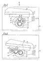
- eine Seitenansicht der Betätigungseinrichtung für die Kupplung mit dem Schalthebel innerhalb der Umlaufbahn der Schaltklinke (Kupplung ausgekuppelt),
- Figur 2a
- die Betätigungseinrichtung für die Kupplung mit dem Schalthebel außerhalb der Umlaufbahn der Schaltklinke (Kupplung eingekuppelt),
- Figur 2b
- die Betätigungseinrichtung für die Kupplung mit dem Schalthebel außerhalb der Umlaufbahn der Schaltklinke, wobei sich die Schaltklinke in der unteren Stellung befindet (Kupplung eingekuppelt),
- Figur 3
- die Steuerungsvorrichtung für den Schalthebel in der Ansicht III nach Figur 5,
- Figur 4
- die Steuerungsvorrichtung für den Schalthebel in der Ansicht IV nach Figur 5,
- Figur 5
- die Steuerungsvorrichtung im Schnitt V - V nach Figur 4,
- Figur 6
- die Steuerungsvorrichtung in einer Schnittdarstellung nach Figur 2a.
- 1 -
- Großballenpresse
- 2 -
- Zuführkanal
- 3 -
- Preßkolben
- 4 -
- Preßkanal
- 5 -
- Vorlegewelle
- 6 -
- Knoterwelle
- 7, 8 -
- Stirnrad
- 9 -
- Bindenadeln
- 10 -
- Kupplung
- 11 -
- Kurbel
- 12 -
- Zugstange
- 13 -
- Schwingarm
- 14 -
- Schalthebel
- 15 -
- Sternrad
- 16 -
- Elektromotor
- 17 -
- Pressenrahmen
- 18 -
- Lagerplatte
- 19 -
- Konsole
- 20 -
- Achse
- 21 -
- Ausgangswelle
- 22 -
- Kurbelarm
- 23 -
- Kontaktrolle
- 24 -
- Nocken
- 25 -
- Formteil
- 26 -
- Kontaktbolzen
- 27 -
- Tragbolzen
- 28, 29 -
- Flächen
- 30 -
- Ausnehmung
- 31 -
- Kopfende
- 32 -
- Schenkelfeder
- 33 -
- Zugfeder
- 34
- Schaltklinke
- 35 -
- Auflage
- 36 -
- Gleitplatte
- 37 -
- Anschlagfläche
Claims (12)
- Einrichtung zum Betätigen der Kupplung für die Bindeeinrichtung einer Großballenpresse für landwirtschaftliches Erntegut mit einer Vorrichtung zum Ermitteln der Ballenlänge und einer mit dieser zusammenwirkenden Steuerungsvorrichtung für einen schwenkbar gelagerten Schalthebel für die Kupplung, gekennzeichnet durch folgende Merkmale:a) die Vorrichtung zum Ermitteln der Ballenlänge ist über eine elektrische Schaltung mit einem Elektromotor (16) verbunden,b) der Elektromotor (16) ist mit der Steurungsvorrichtung für den Schalthebel (14) antriebsverbunden,c) die Steuerungsvorrichtung steht über einen Nocken (24) mit dem Kontaktbereich des Schalthebeln in Verbindung,d) der Schalthebel (14) ist in Abhängikeit von der Bewegung des Nockens (24) in die Umlaufbahn einer Schaltklinke (34) der Kupplung (10) schwenkbar.
- Einrichtung nach Anspruch 1, dadurch gekennzeichnet,
dadurch gekennzeichnet,
daß die Steuerungseinrichtung für die Schalthebel (14) unterhalb des Kontaktbereiches des Schalthebels 14 angeordnet ist. - Einrichtung nach den Anspruch 1 und 2,
dadurch gekennzeichnet,
daß der Elektromotor (16) vorzugsweise als Scheibenwischermotor ausgebildet ist. - Einrichtung nach Anspruch 1 bis 3,
dadurch gekennzeichnet,
daß an der Ausgangswelle (21) des Elektromotors (16) ein Kurbelarm (22) befestigt ist, an dessen freiem Ende eine drehbare Kontaktrolle (23) angeordnet ist. - Einrichtung nach Anspruch 1 und 4,
dadurch gekennzeichnet,
daß die Kontaktrolle (23) mit einem Nocken (24) in Verbindung steht. - Einrichtung nach Anspruch 1 und 5,
dadurch gekennzeichnet,
daß der Nocken (24) aus einem Formteil (25) und einem damit fest verbundenen Kontaktbolzen (26) besteht. - Einrichtung nach Anspruch 6,
dadurch gekennzeichnet,
daß der Kontaktbolzen (26) an beiden Enden über das Formteil (25) übersteht. - Einrichtung nach Anspruch 1 und 5 bis 7,
dadurch gekennzeichnet,
daß der Nocken (24) auf einem drehfest in einer Konsole (19) angeordneten Tragbolzen (27) geführt und um diesen schwenkbar ist. - Einrichtung nach Anspruch 1 und 5 bis 8,
dadurch gekennzeichnet,
daß der Kontaktbolzen (26) an seinem der Kontakrolle (24) zugewandten Endbereich zwei angeformte Kontaktflächen (28, 29) aufweist. - Einrichtung nach Anspruch 1 und 5 bis 9,
dadurch gekennzeichnet,
daß neben dem Stirnseitenbereich des Kontaktbolzens (26) die Konsole (19) mit einer nierenförmigen, sich schräg nach oben erstreckenden Ausnehmung (30) versehen ist, in die das benachbarte Ende des Kontaktbolzens (26) geführt ist. - Einrichtung nach Anspruch 8,
dadurch gekennzeichnet,
daß das Kopfende (31) des Tragbolzens (27) von einer Schenkelfeder (32) umgeben ist, wobei der eine Schenkel am Tragbolzen (27) und der andere Schenkel am Kontaktbolzen (26) befestigt ist. - Einrichtung nach Anspruch 1 und 2,
dadurch gekennzeichnet,
daß zwischen dem Pressenrahmen (17) und dem Endbereich des Schalthebels (14) eine Zugfeder (33) angeordnet ist.
Applications Claiming Priority (2)
| Application Number | Priority Date | Filing Date | Title |
|---|---|---|---|
| DE19851021 | 1998-11-05 | ||
| DE19851021A DE19851021A1 (de) | 1998-11-05 | 1998-11-05 | Einrichtung zum Betätigen einer Kupplung für die Bindeeinrichtung einer Großballenpresse |
Publications (2)
| Publication Number | Publication Date |
|---|---|
| EP0998845A1 true EP0998845A1 (de) | 2000-05-10 |
| EP0998845B1 EP0998845B1 (de) | 2004-07-28 |
Family
ID=7886807
Family Applications (1)
| Application Number | Title | Priority Date | Filing Date |
|---|---|---|---|
| EP99121385A Expired - Lifetime EP0998845B1 (de) | 1998-11-05 | 1999-10-27 | Einrichtung zum Betätigen einer Kupplung für die Bindeeinrichtung einer Grossballenpresse |
Country Status (5)
| Country | Link |
|---|---|
| US (1) | US6318250B1 (de) |
| EP (1) | EP0998845B1 (de) |
| AT (1) | ATE271761T1 (de) |
| DE (2) | DE19851021A1 (de) |
| PL (1) | PL189515B1 (de) |
Cited By (1)
| Publication number | Priority date | Publication date | Assignee | Title |
|---|---|---|---|---|
| EP3903562A1 (de) * | 2020-04-29 | 2021-11-03 | Maschinenfabrik Bernard Krone GmbH & Co. KG | Bindevorrichtung für eine landwirtschaftliche erntegutpresse und landwirtschaftliche erntegutpresse mit einer solchen bindevorrichtung |
Families Citing this family (6)
| Publication number | Priority date | Publication date | Assignee | Title |
|---|---|---|---|---|
| US6725766B2 (en) * | 2002-01-02 | 2004-04-27 | Deere & Company | Independently powered knotter and needle drive arrangement for a large rectangular baler |
| BE1018763A3 (nl) * | 2009-05-27 | 2011-08-02 | Cnh Belgium Nv | Een methode voor het aansturen van een draadreminrichting van een rechhoekige balenpers. |
| US8141480B2 (en) | 2010-08-23 | 2012-03-27 | Cnh America Llc | Automatic bale size calibration on round balers |
| US12376528B2 (en) * | 2019-12-30 | 2025-08-05 | Agco Corporation | Square baler needle lockout device |
| CN111226615B (zh) * | 2020-03-02 | 2022-04-22 | 安徽中科智能感知产业技术研究院有限责任公司 | 一种基于磁力传感器的方型秸秆捆打捆机的打捆长度实时在线检测方法 |
| CN115388097A (zh) * | 2022-08-23 | 2022-11-25 | 铁建重工新疆有限公司 | 一种用于打结器的电控离合机构和具有该机构的打捆机 |
Citations (6)
| Publication number | Priority date | Publication date | Assignee | Title |
|---|---|---|---|---|
| DE767505C (de) * | 1937-12-12 | 1952-11-24 | & Eisengiesserei Lauingen Koed | Kupplung an Stroh- oder aehnlichen Pressen fuer die Bindevorrichtung |
| DE2738500A1 (de) | 1976-08-30 | 1978-03-02 | Sperry Rand Corp | Kupplungsanordnung, insbesondere fuer eine verschnuervorrichtung bei ballenpressen |
| US4649812A (en) * | 1985-01-25 | 1987-03-17 | Rivierre Casalis | Tying mechanism for rolled bales in a hay baler |
| EP0293025A1 (de) * | 1987-05-01 | 1988-11-30 | FORD NEW HOLLAND, INC. (a Delaware corp.) | Schneidvorrichtung für Netzgewebespender |
| EP0573342A1 (de) | 1992-06-05 | 1993-12-08 | Greenland France Sa. | Ballenpresse für Futter |
| US5783816A (en) * | 1996-10-09 | 1998-07-21 | Mcpherson; Bobby Roy | Measuring device for a hay baler |
Family Cites Families (13)
| Publication number | Priority date | Publication date | Assignee | Title |
|---|---|---|---|---|
| DE594733C (de) * | 1932-08-28 | 1934-03-21 | August Claas | Vorrichtung zum Kuppeln der Binderwelle von Strohpressen o. dgl. mit ihrem Antrieb |
| US2633794A (en) * | 1948-02-26 | 1953-04-07 | J A Freeman & Son | Hay baler |
| US2636582A (en) * | 1949-03-18 | 1953-04-28 | Harrington Mfg Co | Clutch for baling machines for farm products |
| US2560143A (en) * | 1950-11-06 | 1951-07-10 | Battista A Vietti | Trip unit for automatic baling machines |
| US2746584A (en) * | 1953-04-02 | 1956-05-22 | Deere Mfg Co | Safety control for self-interrupting clutch |
| US2713303A (en) * | 1953-07-08 | 1955-07-19 | Wade D Hill | Hay baler |
| US4095520A (en) * | 1976-09-20 | 1978-06-20 | Burford Charles E | Horizontal baler |
| CA1198012A (en) | 1982-10-07 | 1985-12-17 | Abram J. Olfert | Bale length controlling sprocket for baling machines |
| FR2542969B1 (fr) | 1983-03-22 | 1986-03-14 | Rivierre Casalis | Presse a piston pour formage de balles de fourrage |
| FR2597699B1 (fr) | 1986-04-25 | 1990-10-12 | Rivierre Casalis | Ensemble constitue par une presse ramasseuse de produits agricoles attelee a un tracteur. |
| JPH03139208A (ja) * | 1989-10-23 | 1991-06-13 | Kubota Corp | 結束装置 |
| JPH03155705A (ja) * | 1989-11-14 | 1991-07-03 | Kubota Corp | 農用結束装置 |
| US5855166A (en) * | 1996-10-09 | 1999-01-05 | Mcpherson; Bobby Roy | Retrofit measuring device for a hay baler |
-
1998
- 1998-11-05 DE DE19851021A patent/DE19851021A1/de not_active Withdrawn
-
1999
- 1999-10-27 EP EP99121385A patent/EP0998845B1/de not_active Expired - Lifetime
- 1999-10-27 DE DE59910055T patent/DE59910055D1/de not_active Expired - Fee Related
- 1999-10-27 AT AT99121385T patent/ATE271761T1/de not_active IP Right Cessation
- 1999-11-04 PL PL99336442A patent/PL189515B1/pl unknown
- 1999-11-05 US US09/434,538 patent/US6318250B1/en not_active Expired - Fee Related
Patent Citations (6)
| Publication number | Priority date | Publication date | Assignee | Title |
|---|---|---|---|---|
| DE767505C (de) * | 1937-12-12 | 1952-11-24 | & Eisengiesserei Lauingen Koed | Kupplung an Stroh- oder aehnlichen Pressen fuer die Bindevorrichtung |
| DE2738500A1 (de) | 1976-08-30 | 1978-03-02 | Sperry Rand Corp | Kupplungsanordnung, insbesondere fuer eine verschnuervorrichtung bei ballenpressen |
| US4649812A (en) * | 1985-01-25 | 1987-03-17 | Rivierre Casalis | Tying mechanism for rolled bales in a hay baler |
| EP0293025A1 (de) * | 1987-05-01 | 1988-11-30 | FORD NEW HOLLAND, INC. (a Delaware corp.) | Schneidvorrichtung für Netzgewebespender |
| EP0573342A1 (de) | 1992-06-05 | 1993-12-08 | Greenland France Sa. | Ballenpresse für Futter |
| US5783816A (en) * | 1996-10-09 | 1998-07-21 | Mcpherson; Bobby Roy | Measuring device for a hay baler |
Cited By (1)
| Publication number | Priority date | Publication date | Assignee | Title |
|---|---|---|---|---|
| EP3903562A1 (de) * | 2020-04-29 | 2021-11-03 | Maschinenfabrik Bernard Krone GmbH & Co. KG | Bindevorrichtung für eine landwirtschaftliche erntegutpresse und landwirtschaftliche erntegutpresse mit einer solchen bindevorrichtung |
Also Published As
| Publication number | Publication date |
|---|---|
| DE59910055D1 (de) | 2004-09-02 |
| EP0998845B1 (de) | 2004-07-28 |
| PL336442A1 (en) | 2000-05-08 |
| US6318250B1 (en) | 2001-11-20 |
| DE19851021A1 (de) | 2000-05-11 |
| ATE271761T1 (de) | 2004-08-15 |
| PL189515B1 (pl) | 2005-08-31 |
Similar Documents
| Publication | Publication Date | Title |
|---|---|---|
| EP0940072B1 (de) | Presse mit einem Ballenpressraum, einem Kolben und einem hydraulischen Betätigungsglied | |
| DE19715280A1 (de) | Kolbenpresse zur Herstellung von Preßballen aus Erntegut | |
| EP0998845B1 (de) | Einrichtung zum Betätigen einer Kupplung für die Bindeeinrichtung einer Grossballenpresse | |
| DE69801615T2 (de) | Sicherheitsvorrichtung für eine Nadelauslöseeinrichtung | |
| WO2004070147A1 (de) | Türöffnungshilfe | |
| DE2749486C2 (de) | ||
| EP3903563B1 (de) | Förder- und sammelvorrichtung mit einer antreibbaren förder- und sammeleinheit und landwirtschaftliche erntegutpresse mit der förder- und sammelvorrichtung | |
| DE20104700U1 (de) | Kolbenpresse | |
| DE10247979B4 (de) | Kraftfahrzeugschloss, vorzugsweise Kofferraum- oder Heckklappenschloss | |
| EP3903562A1 (de) | Bindevorrichtung für eine landwirtschaftliche erntegutpresse und landwirtschaftliche erntegutpresse mit einer solchen bindevorrichtung | |
| DE60224641T2 (de) | Garnknüpferantrieb | |
| DE10244816B4 (de) | Antriebsvorrichtung für die Bindeeinrichtung von Großballenpressen | |
| EP4588335A1 (de) | Bindeeinrichtung für eine quaderballenpresse | |
| DE19812861B4 (de) | Elektrokettensäge | |
| DE10230586B4 (de) | Kraftfahrzeugtürverschluss | |
| DE69205503T2 (de) | Verbesserter Antriebsmechanismus für einen elektrischen Schalter, insbesondere Schutzschalter oder Leistungsschalter. | |
| DE810819C (de) | Sicherheitsvorrichtung fuer Ballenpressen | |
| DE102024101262A1 (de) | Bindeeinrichtung für eine Quaderballenpresse | |
| DE4232711C2 (de) | Ballenpresse für landwirtschaftliches Erntegut | |
| DE2911906C2 (de) | Schalteinrichtung für den Binderwellen- und Nadelantrieb einer Aufsammelballenpresse | |
| DE10329136A1 (de) | Knoteneinrichtung für eine Großballenpresse | |
| DE2807779A1 (de) | Kupplungsgestaenge | |
| EP0442108A1 (de) | Kolbenpresse zur Herstellung von Pressballen aus Erntegut | |
| DE19508931A1 (de) | Ballenpresse | |
| DD150835A1 (de) | Steuereinrichtung fuer eine ballenpackkammer zur herstellung von grossballen |
Legal Events
| Date | Code | Title | Description |
|---|---|---|---|
| PUAI | Public reference made under article 153(3) epc to a published international application that has entered the european phase |
Free format text: ORIGINAL CODE: 0009012 |
|
| AK | Designated contracting states |
Kind code of ref document: A1 Designated state(s): AT BE CH CY DE DK ES FI FR GB GR IE IT LI LU MC NL PT SE |
|
| AX | Request for extension of the european patent |
Free format text: AL;LT;LV;MK;RO;SI |
|
| 17P | Request for examination filed |
Effective date: 20001110 |
|
| AKX | Designation fees paid |
Free format text: AT BE CH CY DE DK ES FI FR GB GR IE IT LI LU MC NL PT SE |
|
| 17Q | First examination report despatched |
Effective date: 20030213 |
|
| GRAP | Despatch of communication of intention to grant a patent |
Free format text: ORIGINAL CODE: EPIDOSNIGR1 |
|
| GRAS | Grant fee paid |
Free format text: ORIGINAL CODE: EPIDOSNIGR3 |
|
| GRAA | (expected) grant |
Free format text: ORIGINAL CODE: 0009210 |
|
| AK | Designated contracting states |
Kind code of ref document: B1 Designated state(s): AT BE CH CY DE DK ES FI FR GB GR IE IT LI LU MC NL PT SE |
|
| PG25 | Lapsed in a contracting state [announced via postgrant information from national office to epo] |
Ref country code: NL Free format text: LAPSE BECAUSE OF FAILURE TO SUBMIT A TRANSLATION OF THE DESCRIPTION OR TO PAY THE FEE WITHIN THE PRESCRIBED TIME-LIMIT Effective date: 20040728 Ref country code: IE Free format text: LAPSE BECAUSE OF FAILURE TO SUBMIT A TRANSLATION OF THE DESCRIPTION OR TO PAY THE FEE WITHIN THE PRESCRIBED TIME-LIMIT Effective date: 20040728 Ref country code: FI Free format text: LAPSE BECAUSE OF FAILURE TO SUBMIT A TRANSLATION OF THE DESCRIPTION OR TO PAY THE FEE WITHIN THE PRESCRIBED TIME-LIMIT Effective date: 20040728 Ref country code: CY Free format text: LAPSE BECAUSE OF FAILURE TO SUBMIT A TRANSLATION OF THE DESCRIPTION OR TO PAY THE FEE WITHIN THE PRESCRIBED TIME-LIMIT Effective date: 20040728 |
|
| REG | Reference to a national code |
Ref country code: GB Ref legal event code: FG4D Free format text: NOT ENGLISH |
|
| REG | Reference to a national code |
Ref country code: CH Ref legal event code: EP |
|
| REG | Reference to a national code |
Ref country code: IE Ref legal event code: FG4D Free format text: GERMAN |
|
| REF | Corresponds to: |
Ref document number: 59910055 Country of ref document: DE Date of ref document: 20040902 Kind code of ref document: P |
|
| PG25 | Lapsed in a contracting state [announced via postgrant information from national office to epo] |
Ref country code: AT Free format text: LAPSE BECAUSE OF NON-PAYMENT OF DUE FEES Effective date: 20041027 |
|
| PG25 | Lapsed in a contracting state [announced via postgrant information from national office to epo] |
Ref country code: SE Free format text: LAPSE BECAUSE OF FAILURE TO SUBMIT A TRANSLATION OF THE DESCRIPTION OR TO PAY THE FEE WITHIN THE PRESCRIBED TIME-LIMIT Effective date: 20041028 Ref country code: GR Free format text: LAPSE BECAUSE OF FAILURE TO SUBMIT A TRANSLATION OF THE DESCRIPTION OR TO PAY THE FEE WITHIN THE PRESCRIBED TIME-LIMIT Effective date: 20041028 Ref country code: DK Free format text: LAPSE BECAUSE OF FAILURE TO SUBMIT A TRANSLATION OF THE DESCRIPTION OR TO PAY THE FEE WITHIN THE PRESCRIBED TIME-LIMIT Effective date: 20041028 |
|
| PG25 | Lapsed in a contracting state [announced via postgrant information from national office to epo] |
Ref country code: MC Free format text: LAPSE BECAUSE OF NON-PAYMENT OF DUE FEES Effective date: 20041031 Ref country code: LU Free format text: LAPSE BECAUSE OF NON-PAYMENT OF DUE FEES Effective date: 20041031 Ref country code: LI Free format text: LAPSE BECAUSE OF NON-PAYMENT OF DUE FEES Effective date: 20041031 Ref country code: CH Free format text: LAPSE BECAUSE OF NON-PAYMENT OF DUE FEES Effective date: 20041031 |
|
| PG25 | Lapsed in a contracting state [announced via postgrant information from national office to epo] |
Ref country code: ES Free format text: LAPSE BECAUSE OF FAILURE TO SUBMIT A TRANSLATION OF THE DESCRIPTION OR TO PAY THE FEE WITHIN THE PRESCRIBED TIME-LIMIT Effective date: 20041108 |
|
| GBT | Gb: translation of ep patent filed (gb section 77(6)(a)/1977) |
Effective date: 20041019 |
|
| NLV1 | Nl: lapsed or annulled due to failure to fulfill the requirements of art. 29p and 29m of the patents act | ||
| ET | Fr: translation filed | ||
| REG | Reference to a national code |
Ref country code: IE Ref legal event code: FD4D |
|
| PLBE | No opposition filed within time limit |
Free format text: ORIGINAL CODE: 0009261 |
|
| STAA | Information on the status of an ep patent application or granted ep patent |
Free format text: STATUS: NO OPPOSITION FILED WITHIN TIME LIMIT |
|
| REG | Reference to a national code |
Ref country code: CH Ref legal event code: PL |
|
| 26N | No opposition filed |
Effective date: 20050429 |
|
| PG25 | Lapsed in a contracting state [announced via postgrant information from national office to epo] |
Ref country code: PT Free format text: LAPSE BECAUSE OF NON-PAYMENT OF DUE FEES Effective date: 20041228 |
|
| PGFP | Annual fee paid to national office [announced via postgrant information from national office to epo] |
Ref country code: DE Payment date: 20070828 Year of fee payment: 9 |
|
| PG25 | Lapsed in a contracting state [announced via postgrant information from national office to epo] |
Ref country code: DE Free format text: LAPSE BECAUSE OF NON-PAYMENT OF DUE FEES Effective date: 20090501 |
|
| REG | Reference to a national code |
Ref country code: FR Ref legal event code: PLFP Year of fee payment: 17 |
|
| PGFP | Annual fee paid to national office [announced via postgrant information from national office to epo] |
Ref country code: GB Payment date: 20151021 Year of fee payment: 17 |
|
| REG | Reference to a national code |
Ref country code: FR Ref legal event code: PLFP Year of fee payment: 18 |
|
| GBPC | Gb: european patent ceased through non-payment of renewal fee |
Effective date: 20161027 |
|
| PG25 | Lapsed in a contracting state [announced via postgrant information from national office to epo] |
Ref country code: GB Free format text: LAPSE BECAUSE OF NON-PAYMENT OF DUE FEES Effective date: 20161027 |
|
| REG | Reference to a national code |
Ref country code: FR Ref legal event code: PLFP Year of fee payment: 19 |
|
| PGFP | Annual fee paid to national office [announced via postgrant information from national office to epo] |
Ref country code: FR Payment date: 20171024 Year of fee payment: 19 |
|
| PGFP | Annual fee paid to national office [announced via postgrant information from national office to epo] |
Ref country code: IT Payment date: 20171023 Year of fee payment: 19 Ref country code: BE Payment date: 20171019 Year of fee payment: 19 |
|
| REG | Reference to a national code |
Ref country code: BE Ref legal event code: MM Effective date: 20181031 |
|
| PG25 | Lapsed in a contracting state [announced via postgrant information from national office to epo] |
Ref country code: BE Free format text: LAPSE BECAUSE OF NON-PAYMENT OF DUE FEES Effective date: 20181031 Ref country code: FR Free format text: LAPSE BECAUSE OF NON-PAYMENT OF DUE FEES Effective date: 20181031 |
|
| PG25 | Lapsed in a contracting state [announced via postgrant information from national office to epo] |
Ref country code: IT Free format text: LAPSE BECAUSE OF NON-PAYMENT OF DUE FEES Effective date: 20181027 |