EP0997221A2 - Méthode et appareil pour l'usinage en trois dimensions d'une pièce par électroérosion ou usinage électrochimique - Google Patents
Méthode et appareil pour l'usinage en trois dimensions d'une pièce par électroérosion ou usinage électrochimique Download PDFInfo
- Publication number
- EP0997221A2 EP0997221A2 EP99120782A EP99120782A EP0997221A2 EP 0997221 A2 EP0997221 A2 EP 0997221A2 EP 99120782 A EP99120782 A EP 99120782A EP 99120782 A EP99120782 A EP 99120782A EP 0997221 A2 EP0997221 A2 EP 0997221A2
- Authority
- EP
- European Patent Office
- Prior art keywords
- electrode
- workpiece
- machining
- workpiece surface
- erosion
- Prior art date
- Legal status (The legal status is an assumption and is not a legal conclusion. Google has not performed a legal analysis and makes no representation as to the accuracy of the status listed.)
- Withdrawn
Links
- 238000000034 method Methods 0.000 title claims description 48
- 238000003754 machining Methods 0.000 title claims description 35
- 230000003628 erosive effect Effects 0.000 claims description 51
- 239000007788 liquid Substances 0.000 claims description 14
- 238000011010 flushing procedure Methods 0.000 claims description 12
- 238000009413 insulation Methods 0.000 claims description 8
- 239000000463 material Substances 0.000 claims description 3
- 238000005259 measurement Methods 0.000 claims 1
- 238000009760 electrical discharge machining Methods 0.000 description 11
- 230000007850 degeneration Effects 0.000 description 3
- 230000000694 effects Effects 0.000 description 3
- 238000005516 engineering process Methods 0.000 description 3
- 230000009286 beneficial effect Effects 0.000 description 2
- 230000001419 dependent effect Effects 0.000 description 2
- 238000003801 milling Methods 0.000 description 2
- OKTJSMMVPCPJKN-UHFFFAOYSA-N Carbon Chemical compound [C] OKTJSMMVPCPJKN-UHFFFAOYSA-N 0.000 description 1
- 238000005452 bending Methods 0.000 description 1
- 230000001934 delay Effects 0.000 description 1
- 238000001514 detection method Methods 0.000 description 1
- 230000005611 electricity Effects 0.000 description 1
- 230000008030 elimination Effects 0.000 description 1
- 238000003379 elimination reaction Methods 0.000 description 1
- 230000002996 emotional effect Effects 0.000 description 1
- 239000012530 fluid Substances 0.000 description 1
- 229910002804 graphite Inorganic materials 0.000 description 1
- 239000010439 graphite Substances 0.000 description 1
- 230000002262 irrigation Effects 0.000 description 1
- 238000003973 irrigation Methods 0.000 description 1
- 230000014759 maintenance of location Effects 0.000 description 1
- 238000004519 manufacturing process Methods 0.000 description 1
- 238000003701 mechanical milling Methods 0.000 description 1
- 239000002245 particle Substances 0.000 description 1
- 230000000750 progressive effect Effects 0.000 description 1
- 239000000523 sample Substances 0.000 description 1
- 239000007787 solid Substances 0.000 description 1
Images


Classifications
-
- B—PERFORMING OPERATIONS; TRANSPORTING
- B23—MACHINE TOOLS; METAL-WORKING NOT OTHERWISE PROVIDED FOR
- B23H—WORKING OF METAL BY THE ACTION OF A HIGH CONCENTRATION OF ELECTRIC CURRENT ON A WORKPIECE USING AN ELECTRODE WHICH TAKES THE PLACE OF A TOOL; SUCH WORKING COMBINED WITH OTHER FORMS OF WORKING OF METAL
- B23H7/00—Processes or apparatus applicable to both electrical discharge machining and electrochemical machining
- B23H7/26—Apparatus for moving or positioning electrode relatively to workpiece; Mounting of electrode
-
- B—PERFORMING OPERATIONS; TRANSPORTING
- B23—MACHINE TOOLS; METAL-WORKING NOT OTHERWISE PROVIDED FOR
- B23H—WORKING OF METAL BY THE ACTION OF A HIGH CONCENTRATION OF ELECTRIC CURRENT ON A WORKPIECE USING AN ELECTRODE WHICH TAKES THE PLACE OF A TOOL; SUCH WORKING COMBINED WITH OTHER FORMS OF WORKING OF METAL
- B23H1/00—Electrical discharge machining, i.e. removing metal with a series of rapidly recurring electrical discharges between an electrode and a workpiece in the presence of a fluid dielectric
-
- B—PERFORMING OPERATIONS; TRANSPORTING
- B23—MACHINE TOOLS; METAL-WORKING NOT OTHERWISE PROVIDED FOR
- B23H—WORKING OF METAL BY THE ACTION OF A HIGH CONCENTRATION OF ELECTRIC CURRENT ON A WORKPIECE USING AN ELECTRODE WHICH TAKES THE PLACE OF A TOOL; SUCH WORKING COMBINED WITH OTHER FORMS OF WORKING OF METAL
- B23H7/00—Processes or apparatus applicable to both electrical discharge machining and electrochemical machining
- B23H7/26—Apparatus for moving or positioning electrode relatively to workpiece; Mounting of electrode
- B23H7/30—Moving electrode in the feed direction
Definitions
- the invention relates to a method and an apparatus for the three-dimensional electroerosive (EDM) or electrochemical (ECM) Machining curved surfaces in a workpiece using one generally independent of the shape of the curved surface Electrode according to the preambles of claims 1 and 14.
- Electrode holder in the X, Y and Z directions over the workpiece guided.
- erosion pulses placed in the form of voltage pulses on the electrode and the machining gap between the electrode and the workpiece is rinsed.
- the electrode is placed over the workpiece surface in the manner of a milling machine led and carries the individual in layers sections of the workpiece to be eroded, in which the curved surface is to be formed. This method allows high wear, which is compensated.
- Such an electrical erosion device is known from US 4,504,721 known that works with a hollow electrode through which the Flushing liquid during processing in the processing gap is pressed.
- electrode wear occurs during the erosion process inevitable, which changes the shape of the electrode over the course of the Editing changed. Will the electrode during processing also set in rotation, this results, for example that shown in the lower right half of the figure in FIG. 1a Wear profile of the electrode.
- Such an electrical erosion device is, for example, from EP 555 818 A1 known, in which the electrode in rotation is transferred.
- the wear profile changes depending on several parameters. But that changes also the contact surface of the electrode depends on the state of wear. So is a given generator setting a certain wear (wear rate) and a corresponding one Wear profile before.
- electrode wear is also known to measure and then on the basis of the measured values To compensate for pushing the electrode.
- DE 30 36 462 A1 is such an electrical discharge machining device known in which the electrode in addition to their movement in the X, Y and Z directions when "milling out” the concave Surface is still vibrated. The vibrations are subsequently detected by a detection device, whereby the wear of the electrode can be determined.
- the minimum radius that erodes depending on the width of the machining gap and the radius of the electrode because of this, be ordinary only electrodes with a small diameter, i.e. thin ones cylindrical electrodes with a small contact surface are used. So with the small attack surface still a satisfactory one Removal rate can be achieved, the electrode rotated to support the flush. With this Measure can be the maximum allowable current density and thus the removal rate will also be increased.
- thin electrodes have the disadvantage that they are not sufficient are stiff and under the action of the rinsing and erosion forces bend, which deteriorates the machining accuracy becomes. It can also occur in the event of a collision thin electrode with the workpiece, etc. to a plastic one Deformation of the electrode.
- the electrode profile or the electrode geometry changes during processing, especially occurs lateral electrode wear.
- the electrodes not sufficiently rigid. Therefore, the known Device achievable machining accuracy strong limited.
- a spark erosion device is known from DE 33 36 034 C2, where a rod-shaped electrode with circular or square cross-section along a preprogrammed feed path is moved.
- the feed tracks run in layers in parallel planes.
- the electrode is along a previously for each machining point certain retraction path from the machining area moved away. From the return lanes calculated in advance there are no unnecessary delays in the withdrawal movement.
- a spark erosion device with a rotatable electrode is also known from DE 32 03 605 A1.
- the electrode has several different machining sides (different profile) running parallel to its longitudinal axis, which can be used for machining the workpiece depending on the rotary position of the electrode.
- the invention has for its object to keep the electrode profile largely constant during processing.
- a feed tangential to the workpiece surface the longitudinal axis of the electrode against the normal on the Workpiece surface is inclined so that it is on the workpiece opposite end deflected against the feed direction is.
- the contact surface of the electrode is thereby advantageous double that of the prior art. With the same current density, the Electricity doubles and thus the rate of erosion more than doubles become. This is particularly clear from one example Comparison of Figures 1a and 1b can be seen. In the case of Fig. 1a shown electrode from the prior art is the contact surface on the underside of the electrode only - in the feed direction seen the electrode - in the front section.
- a key advantage is that the profile of the Electrode changes only slightly during its wear.
- the electrode wears evenly on its underside, whereby the wear by correspondingly pushing the Electrode can be easily compensated.
- the profile will be there not changed.
- feed direction of the electrode Understand the direction in which the electrode holder to Following a predetermined eroding path is moved.
- the tool table can also be adjusted accordingly with the tool clamped be moved.
- workpiece surface is used locally in the Unprocessed, possibly curved, area of the electrode Understood surface section that will be processed next shall be.
- the shape of the electrode is independent of that Shape of the curved surface to be eroded.
- the deflection angle is preferably dependent on the processing quality set (claim 2), wherein the deflection angle particularly preferably against the last finishing step Is reset (claim 3). This can be advantageous the removal rate for the coarser processing steps corresponding greater deflection or inclination of the electrode be increased, taking this for the fine machining steps Deflection angle reduced in favor of machining accuracy becomes.
- Material is preferably layered into the depth of the workpiece removed (claim 4).
- the electrode in the direction is preferred their longitudinal axis is lifted from the workpiece surface and then tangent to the workpiece surface on the workpiece surface put back on (claim 5).
- the process degeneracy can be interrupted particularly quickly, and progressively resume erosion.
- the electrode is preferred during processing at time intervals or rotates continuously (claim 6). It is preferred in the case of electroerosive machining with a prismatic one Electrode the electrode before rotating from the machining surface withdrawn (claim 7). This will be advantageous also the last remaining uneven wear of the Electrode compensated.
- the electrode is preferably rinsed centrally, for which Rinsing the rinsing liquid is sucked in through the electrode and the flushing pressure is controlled (claim 10).
- Rinsing the rinsing liquid is sucked in through the electrode and the flushing pressure is controlled (claim 10).
- the duration is preferred the erosion impulses, especially during a pressure flush chosen less than the throughput time of a discharge, which arise at the electrode center and independently at the electrode edge would delete (claim 11).
- the erosion impulses are chosen to be as long as possible, almost to direct current erosion.
- the erosion voltage is preferred with regard to a change the arc voltage and / or the superimposed voltage ripple is monitored and if there is a deviation from the setpoint, the erosion pulse is deleted (claim 12). This can be advantageous Damage to the electrode can be avoided.
- the electrode with a lateral insulation layer is preferred coated (claim 17).
- This insulation layer has an advantageous effect, which is preferably made particularly thin, damage to the electrode on its side wall.
- Such an electrode can also be independent of the one according to the invention Device are used, for example in known electrical erosion devices to the lateral Reduce electrode wear.
- Fig. 1a is an electrode 1 when processing in layers a workpiece 2 at the beginning and in the course of processing shown according to a known method.
- the electrode 1 In the left half of the figure the electrode 1 is placed on the workpiece 2. in the The further course of the processing should remove the layer thickness d.
- the electrode 1 is moved along the feed direction V emotional.
- the processing is already in the right half of the figure advanced, causing the electrode 1 to wear experienced.
- the wear profile is below the right one Figure half shown enlarged.
- the black areas mean removed portions of the electrode 1.
- the symmetrical Wear profile stems from rotation of the electrode 1.
- Fig. 1b is the corresponding electrode 1 when removing the Layer thickness d of the workpiece 2 at the beginning and in the course the processing according to the inventive method shown.
- the XY main level is understood to mean the level which through the X and Y main axes of the machine tool is spanned.
- the main axes on an EDM device so that the horizontal workpiece plane, i.e. the horizontal surface of the workpiece a workpiece clamped on the device extends parallel to the main XY plane.
- the feed of the electrode holder in three-dimensional eroding within this The workpiece is then also removed in layers parallel to this main level.
- the electrode will compensate for its wear as well for eroding in depth (in or along a recess) vertical inner wall) or along a vertical outer surface of the workpiece moves along the Z axis.
- Ramps i.e. inclined planes on a workpiece surface eroded
- the feed is no longer parallel to the XY main plane, but also along the Z main axis.
- one side wall is a deeper one Trench eroded in the workpiece, so generally runs the feed direction parallel to the z main axis.
- the feed direction runs in both Figures 1a and b in the direction the X main axis, i.e. parallel to the XY main plane.
- the longitudinal axis of the electrode is 1 aligned perpendicular to the feed direction V, while at inventive method already the longitudinal axis of the electrode 1 at an angle greater than 90 ° to the feed direction V placed on the workpiece surface and the other Machining appropriately inclined over the workpiece surface is moved.
- FIG. 1b Below the right half of the figure in FIG. 1b is the wear profile of the electrode 1 in the invention Procedure shown. As can be seen from this, a uniform removal of the electrode 1 over its entire underside instead of.
- the inclination according to the invention of the longitudinal axis of the electrode 1 the normal to the workpiece surface when the feed direction V is tangent to the workpiece surface thus also the inclination of the longitudinal axis of the electrode 1 the normal to the workpiece surface when the feed direction parallel to the XY main plane or parallel to the Z main axis lies.
- the electrode 1 is involved in the erosion of a corner the radius r in a sectional view and top view according to a known Procedure shown.
- the electrode 1 is again vertical to the feed direction V.
- an electrode 1 'with a is analogous to FIG. 2a square cross section when eroding the same corner shown the inventive method.
- the electrode 1 'does not have to be moved for retention uniform wear or for an increase in Flush be rotated so that one edge of the square Electrode 1 'can erode the corner.
- For an immediate Size comparison is in the left half of FIG. 2b Cross section of the rotating used in the known method Electrode 1 shown.
- the cross section of the square Electrode can be chosen much larger, although the same Corner radius is cut, reducing both rigidity as well as the surface area of attack and thus the machining accuracy and speed can be increased.
- the machining of a larger recess in the workpiece 2 can according to the inventive method, for example, as follows done:
- the electrode 1 is inclined to the normal up to the workpiece surface from one edge of the recess moved to the opposite edge while several such Lanes are placed in parallel so that the through if possible, the removal of the vacated area has no reefs.
- the electrode 1 is in the vertical pivoted so that there is no ramp on the edge to the side wall remains.
- the Electrode 1 upright along the side edge of the recess, i.e. be moved perpendicular to the feed direction V, so that the Sidewall is formed as perpendicular as possible. Will then the adjacent path in the opposite direction V eroded, the electrode 1 is again inclined accordingly, so that the bottom of the electrode completely against the one to be eroded Layer is applied.
- the optimal electrode movements for example around a corner to erode are preprogrammed.
- the corresponding electroerosion device must be for such Freedom of movement of the electrode holder at least five Have degrees of freedom: three for movement in X, Y and Z direction, one for pivoting the electrode 1 and one for rotating the electrode holder so that the swivel plane is arbitrary can be rotated.
- Figures 3a and 3b is a top view (left half of the figure) and cross-sectional view (right half of the figure) each of the eroding a narrow trench 3 according to the known and the inventive Procedure shown.
- the trench 3 of width b with a cylindrical electrode 1 eroded so that the achievable corner radii r of the trench 3 less than or equal to half due to the electrode geometry Are trench width.
- the rotation requirement with a rectangular electrode 1 'to be worked The corner radii that can be achieved here depend only on the edge sharpness of the rectangular Electrode 1 'and can therefore be much smaller, i.e. more angular his.
- the erosion process is carried out as in the known one Die sinking EDM.
- the electrode 1 in a suitable direction along its longitudinal axis from the Machining surface lifted off so that the erosion side of the Electrode 1 as quickly as possible over its entire cross section is removed from the processing area. In other words should all sections of the erosion side as quickly as possible their nearest machining section.
- This process is indicated by the arrow A in FIG.
- the location of the electrode 1 after the withdrawal is shown in dashed lines. This direction is from the electrode's erosion profile 1 automatically derived and adaptively changed to erosion breaks to minimize.
- the electrode 1 becomes tangential placed on the processing surface, which in Fig. 4 by the arrow B is shown. Then the electrode 1 again moved in the feed direction V during machining and at the same time inclined accordingly until they are solid Lines shown position has reached again. In the Resuming processing can make the pulse rate progressive be increased.
- the electrode 1 can be in predetermined time intervals be rotated to the inevitable remaining irregularities to compensate for their wear.
- the rotation can be done while editing while for all other electrode shapes, especially for electrodes with a prismatic cross-section, the electrode 1 'in front of the Rotation can only be withdrawn from the processing surface got to.
- any type of electrode including cylindrical electrodes 1, 1 'the rotation with the Withdrawal movement can be combined. The amplitude and the direction the retraction movement can thereby be eroded from the Geometry can be derived.
- the method according to the invention also occurs Wear of the electrode 1 as shown in Fig. 1b. This by moving the electrode 1 along accordingly their longitudinal axis is automatically compensated by the replenishment rate from the product of erosion current and erosion time is derived.
- the proportionality factor is for each type of electrode depending on material, shape and cross-section as technology parameters saved.
- the calculated wear rate can be measured at intervals the electrode 1 on a measuring ball 4 (a probe or a other measuring equipment on the device) during the overall processing be checked, resulting in higher machining accuracy can be achieved.
- a measuring ball 4 a probe or a other measuring equipment on the device
- FIG. 5 represents the electrode 1 and the measuring ball 4. How from this figure can be seen, the measuring ball 4 not only measures the length of the electrode 1, but also its lateral wear profile.
- Fig. 6 it is shown how the flowing through the erosion gap Current density can be increased.
- an electrode holder 5, 5 'a piezoelectric translator 6, 6' installed, which the electrode 1, 1 '' over a holder section 7 can vibrate.
- the electrode vibration is especially for electrodes 1, 1 '' with a small cross-section and thus a small contact surface suitable, since the hydrodynamic Forces remain small.
- the electrode holder 5, 5 '(quill) does not have to be 1' 'either be stiff because of bending due to hydrodynamic Forces is low.
- the piezoelectric translator 6 can also other suitable means are used.
- the former are because of their high achievable vibration frequency suitable, which is advantageously above the natural frequency of the Electro-erosion device can lie.
- 6 is in the left half of the figure a corresponding electrode holder 5 ' shown for a hollow electrode 1 '' with rinsing channel 8, the piezoelectric translator 6 'also has an inner bore 9 has, through which the rinsing liquid can flow.
- the piezoelectric translator 6 In the right half of the figure in FIG. 6, on the other hand, is an electrode holder 5 shown for a solid electrode 1 without a rinsing channel, in which the piezoelectric translator 6 has no inner bore having.
- electrodes 1 '' with a central flush and flush pressure control be used.
- This can be advantageous Current density can be increased further, resulting in a disproportionate Leads to an increase in the removal rate.
- the process is the effect of central flushing optimal, since the pressure drop mainly takes place in the erosion gap. This is easiest from a comparison of the right Figure halves of Figures 1a and 1b can be seen.
- the inventive method is the erosion gap over the entire Underside of electrode of equal size, so that the pressure drop is largely constant over the entire underside.
- the electroerosion device can be designed such that they have a rinsing liquid velocity in the machining gap generated by several meters per second. With this measure the erosion rate compared to conventional die sinking EDM can be increased by a factor of 20.
- the rinsing channel of a (possibly short and simply designed) hollow electrode be suctioned off with a flushing channel.
- the controlled arc runs from the electrode edge towards Rinsing channel inside the electrode and is in the rinsing channel safely deleted (DE 27 33 430 C2). The arc is namely swept away by the rinsing liquid and thus lengthened. If the arc is long enough, it will extinguish by itself.
- the electrode holder 5 can be designed accordingly be that there is a pressure drop at the junction between Electrode 1 '' and electrode holder 5 kept small becomes.
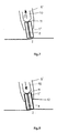
- Fig. 7 is indicated schematically how such Electrode holder 5 'could be formed.
- the top of the collar 11 is designed to open conically, so that no erosion particles accumulate above a collar 11.
- the arrow C shown in FIG. 7 indicates the direction of flow the rinsing liquid.
- the irrigation has from the center of the bottom of the electrode the advantage in the direction of the electrode edge, the freedom of movement to protect.
- the flushing pressure can always be increased in this way that the required dielectric speed is achieved in the erosion gap.
- the DC arc on the outer edge of the electrode to delete. This leads to the electrode 1 ′′ on its Edge is damaged or excessively worn. Because of this To counteract this, the duration of the erosion pulses becomes like this controlled that they are as long as possible, but always shorter than that Lead time of a discharge is that at the electrode center would arise and erase itself at the electrode edge.
- a change in the Arc voltage are tracked, and the erosion pulse at Deviation from the setpoint can be deleted.
- This deviation from Setpoint can be tracked by evaluating the voltage for example based on the amplitude curve and / or based on the amplitude and frequency of the superimposed voltage ripple.
- Electrode 1 ′′ shown with a lateral insulation layer 12.
- the control of the electrical discharge machining device can be designed in this way be that the dimensions, shape and / or information via the feed direction of the electrode 1 directly from one CAD system removed and from a suitable software for Control of the machine tool is used. This can the processing time can be reduced.
- the dimensions of the Electrode 1 or the one basically on a specific electroerosion device usable electrodes for example electrodes contained in an electrode magazine that automatically replaced by the machine tool as required as well as the required technology parameters saved. These technology parameters also include the optimal electrode inclination or change in inclination to elementary Shapes such as inner and outer corners to edit.
- the feed movement of the electrode 1 also pre-calculated online during processing, so to speak become.
- the entire control system can be designed that they are currently not available in the EDM machine Electrode shapes and / or dimensions recommend which one to shorten the processing time or similar could lead. These shapes and / or dimensions are basically available not available, the control can process automatically perform with the available electrodes 1.
Landscapes
- Engineering & Computer Science (AREA)
- Mechanical Engineering (AREA)
- Chemical & Material Sciences (AREA)
- Chemical Kinetics & Catalysis (AREA)
- Electrochemistry (AREA)
- Electrical Discharge Machining, Electrochemical Machining, And Combined Machining (AREA)
Applications Claiming Priority (2)
| Application Number | Priority Date | Filing Date | Title |
|---|---|---|---|
| DE19849577 | 1998-10-27 | ||
| DE19849577A DE19849577C2 (de) | 1998-10-27 | 1998-10-27 | Verfahren und Vorrichtung zum dreidimensionalen Bearbeiten eines Werkstücks mittels elektroerosiver oder elektrochemischer Bearbeitung |
Publications (2)
| Publication Number | Publication Date |
|---|---|
| EP0997221A2 true EP0997221A2 (fr) | 2000-05-03 |
| EP0997221A3 EP0997221A3 (fr) | 2003-05-14 |
Family
ID=7885846
Family Applications (1)
| Application Number | Title | Priority Date | Filing Date |
|---|---|---|---|
| EP99120782A Withdrawn EP0997221A3 (fr) | 1998-10-27 | 1999-10-20 | Méthode et appareil pour l'usinage en trois dimensions d'une pièce par électroérosion ou usinage électrochimique |
Country Status (4)
| Country | Link |
|---|---|
| US (1) | US6454930B1 (fr) |
| EP (1) | EP0997221A3 (fr) |
| JP (1) | JP3200598B2 (fr) |
| DE (1) | DE19849577C2 (fr) |
Families Citing this family (11)
| Publication number | Priority date | Publication date | Assignee | Title |
|---|---|---|---|---|
| GB9925024D0 (en) * | 1999-10-23 | 1999-12-22 | Ultra Systems Limited | Electrochemical machining |
| US7041933B2 (en) * | 2003-04-14 | 2006-05-09 | Meyer Tool, Inc. | Complex hole shaping |
| US20050247569A1 (en) * | 2004-05-07 | 2005-11-10 | Lamphere Michael S | Distributed arc electroerosion |
| US7867374B2 (en) * | 2004-10-01 | 2011-01-11 | Federal-Mogul World Wide, Inc. | Active matrix electrochemical machining apparatus and method |
| US7428444B2 (en) * | 2006-03-30 | 2008-09-23 | Siemens Product Lifecycle Management Software Inc. | Method for under-sizing electrodes for polygonal orbit electric discharge machining |
| JP2009233812A (ja) * | 2008-03-27 | 2009-10-15 | Univ Nihon | 微細形状加工方法及びマイクロチップ |
| US20100017007A1 (en) * | 2008-07-18 | 2010-01-21 | Wolfgang Seibold | Apparatus and Method For Designing an Electrode Shape for an Electrical Discharge Machining Process |
| US8236162B2 (en) * | 2008-09-30 | 2012-08-07 | General Electric Company | Electroerosion machining system and method for electrode wear compensation |
| US8663450B1 (en) * | 2010-11-19 | 2014-03-04 | The United States Of America As Represented By The Secretary Of The Army | Guide bore electrical machining methods |
| EP2881206B1 (fr) * | 2012-07-31 | 2019-01-16 | Makino Milling Machine Co., Ltd. | Procédé d'usinage à décharge électrique |
| CN116871611B (zh) * | 2023-09-07 | 2023-12-15 | 晋中经纬技协机械有限公司 | 线切割设备的定位装置以及线切割设备 |
Family Cites Families (19)
| Publication number | Priority date | Publication date | Assignee | Title |
|---|---|---|---|---|
| NL297174A (fr) * | 1962-10-23 | |||
| LU73498A1 (fr) * | 1975-10-02 | 1977-05-24 | ||
| US4100388A (en) * | 1977-01-07 | 1978-07-11 | Gilbert Meyer | Electroerosion method and apparatus for machining undercut channels in a workpiece |
| US4256555A (en) * | 1978-05-30 | 1981-03-17 | Rolls Royce Limited | Electro-chemical-machining of aerofoil blades |
| FR2465551B1 (fr) * | 1979-09-26 | 1986-01-24 | Inoue Japax Res | Procede et appareil d'usinage par decharges electriques |
| GB2085788B (en) * | 1980-10-15 | 1984-08-08 | Inoue Japax Res | Electroerosively forming three-dimensional cavities |
| JPS57132927A (en) * | 1981-02-03 | 1982-08-17 | Inoue Japax Res Inc | Spark machining device |
| ATE21935T1 (de) | 1981-05-19 | 1986-09-15 | Inst Chimii Tech Redkik | Gerbmittel fuer haeute und verfahren zu dessen herstellung. |
| DE3336034C2 (de) * | 1983-10-04 | 1994-08-04 | Japax Inc | Verfahren und Vorrichtung zur planetären funkenerosiven Bearbeitung eines Werkstückes |
| US4999093A (en) * | 1989-05-01 | 1991-03-12 | Compressor Components Textron Inc. | Electrochemical machine electrode assembly |
| JPH0577113A (ja) | 1991-05-14 | 1993-03-30 | Mitsubishi Materials Corp | 放電加工機 |
| DE69300988T2 (de) * | 1992-02-12 | 1996-08-08 | Charmilles Technologies | Verfahren und Vorrichtung zum elektroerosiven Herstellen hohler 3-D-Kontouren mit einer dünnen rotierenden Elektrode |
| US5244548A (en) * | 1992-05-06 | 1993-09-14 | Lehr Precision Inc. | Multi-cathode ECM apparatus, method, and product therefrom |
| US5313038A (en) * | 1992-12-22 | 1994-05-17 | United Technologies Corporation | EDM drilling of low angle holes |
| JP3567619B2 (ja) * | 1996-06-19 | 2004-09-22 | 三菱電機株式会社 | 放電加工装置及び方法 |
| JP3549688B2 (ja) * | 1996-10-30 | 2004-08-04 | 三菱電機株式会社 | 放電加工方法および放電加工装置 |
| JP3752754B2 (ja) | 1996-11-28 | 2006-03-08 | 株式会社デンソー | 放電加工用電極送り装置 |
| JPH10277846A (ja) | 1997-04-08 | 1998-10-20 | Matsushita Electric Ind Co Ltd | 放電加工機 |
| JPH11285923A (ja) | 1998-04-06 | 1999-10-19 | Mitsubishi Electric Corp | 放電加工装置 |
-
1998
- 1998-10-27 DE DE19849577A patent/DE19849577C2/de not_active Expired - Fee Related
-
1999
- 1999-10-20 EP EP99120782A patent/EP0997221A3/fr not_active Withdrawn
- 1999-10-27 JP JP30545299A patent/JP3200598B2/ja not_active Expired - Fee Related
- 1999-10-27 US US09/427,760 patent/US6454930B1/en not_active Expired - Fee Related
Also Published As
| Publication number | Publication date |
|---|---|
| JP3200598B2 (ja) | 2001-08-20 |
| EP0997221A3 (fr) | 2003-05-14 |
| US6454930B1 (en) | 2002-09-24 |
| JP2000141134A (ja) | 2000-05-23 |
| DE19849577C2 (de) | 2000-12-07 |
| DE19849577A1 (de) | 2000-05-11 |
Similar Documents
| Publication | Publication Date | Title |
|---|---|---|
| DE69300988T2 (de) | Verfahren und Vorrichtung zum elektroerosiven Herstellen hohler 3-D-Kontouren mit einer dünnen rotierenden Elektrode | |
| EP0076997B1 (fr) | Procédé et dispositif pour l'usinage de matière non-conductrice liée à du métal | |
| EP1590712B1 (fr) | Procede pour commander des mouvements relatifs d'un outil par rapport a une piece | |
| DE1690763B1 (de) | Elektroerosive Bearbeitung von metalallischen Werkstucken mittels einer Elektrode | |
| DE3041612C1 (de) | Vorrichtung zur Winkellage-Orientierung von Drahtfuehrungselementen an polar oder kartesisch gesteuerten funkenerosiven Konisch-Schneidanlagen | |
| EP1430983B1 (fr) | Méthode pour formage électrochimique | |
| DE19849577C2 (de) | Verfahren und Vorrichtung zum dreidimensionalen Bearbeiten eines Werkstücks mittels elektroerosiver oder elektrochemischer Bearbeitung | |
| EP3015210B1 (fr) | Traitement électrochimique d'une pièce | |
| DE3142606C2 (fr) | ||
| EP1066801B1 (fr) | Procédé et dispositif pour fabriquer des prothèses médicales en particulier dentaires | |
| DE4222186A1 (de) | Verfahren zum funkenerosiven Feinbearbeiten mittels drahtförmiger Elektroden und funkenerosive Schneidevorrichtung | |
| DE3525683A1 (de) | Verfahren zur gesteuerten rueckzugsbewegung einer senkelelektrode bei einer elektroerosionsmaschine | |
| DE3917913A1 (de) | Drahterodiereinrichtung | |
| DE19710458B4 (de) | Verfahren zum funkenerosiven Bearbeiten | |
| DE4115107C2 (fr) | ||
| EP3072621B1 (fr) | Guide-fil destine a guider un fil-electrode | |
| DE3237412A1 (de) | Verfahren und vorrichtung zur bearbeitung der oberflaechen eines hohlraumes in einem elektrisch leitenden werkstueck | |
| DE2939005A1 (de) | Verfahren und vorrichtung zum drahtschneiden | |
| DE69603223T2 (de) | Elektroerosive Bearbeitungseinrichtung | |
| EP1019219B1 (fr) | Dispositif de mesure sur une machine destinee a l'usinage de pieces avec des dents coupantes, notamment des lames de scie | |
| DE3923356C1 (fr) | ||
| EP1409186B1 (fr) | Dispositif d'erosion comprenant une tete d'erosion concue pour eliminer des elements de connexion metalliques | |
| EP1093878A1 (fr) | Optimisation des paramètres d'usinage pour machine d'usinage par électroérosion | |
| DE3140036C2 (fr) | ||
| EP3290142A1 (fr) | Procédé et dispositif de détermination de l'usure d'electrodes lors de l'electro-érosion |
Legal Events
| Date | Code | Title | Description |
|---|---|---|---|
| PUAI | Public reference made under article 153(3) epc to a published international application that has entered the european phase |
Free format text: ORIGINAL CODE: 0009012 |
|
| AK | Designated contracting states |
Kind code of ref document: A2 Designated state(s): AT BE CH CY DE DK ES FI FR GB GR IE IT LI LU MC NL PT SE |
|
| AX | Request for extension of the european patent |
Free format text: AL;LT;LV;MK;RO;SI |
|
| PUAL | Search report despatched |
Free format text: ORIGINAL CODE: 0009013 |
|
| AK | Designated contracting states |
Designated state(s): AT BE CH CY DE DK ES FI FR GB GR IE IT LI LU MC NL PT SE |
|
| AX | Request for extension of the european patent |
Extension state: AL LT LV MK RO SI |
|
| RIC1 | Information provided on ipc code assigned before grant |
Ipc: 7B 23H 3/00 B Ipc: 7B 23H 7/30 B Ipc: 7B 23H 7/26 A |
|
| 17P | Request for examination filed |
Effective date: 20031112 |
|
| AKX | Designation fees paid |
Designated state(s): CH ES FR GB IT LI |
|
| REG | Reference to a national code |
Ref country code: DE Ref legal event code: 8566 |
|
| 17Q | First examination report despatched |
Effective date: 20060419 |
|
| STAA | Information on the status of an ep patent application or granted ep patent |
Free format text: STATUS: THE APPLICATION HAS BEEN WITHDRAWN |
|
| 18W | Application withdrawn |
Effective date: 20070626 |