EP0996581B1 - Satellitenfahrzeug zum ein- und auslagern von paletteneinheiten bei transportfahrzeugen - Google Patents
Satellitenfahrzeug zum ein- und auslagern von paletteneinheiten bei transportfahrzeugen Download PDFInfo
- Publication number
- EP0996581B1 EP0996581B1 EP99914554A EP99914554A EP0996581B1 EP 0996581 B1 EP0996581 B1 EP 0996581B1 EP 99914554 A EP99914554 A EP 99914554A EP 99914554 A EP99914554 A EP 99914554A EP 0996581 B1 EP0996581 B1 EP 0996581B1
- Authority
- EP
- European Patent Office
- Prior art keywords
- tines
- vehicle according
- auxiliary vehicle
- lift truck
- pallet
- Prior art date
- Legal status (The legal status is an assumption and is not a legal conclusion. Google has not performed a legal analysis and makes no representation as to the accuracy of the status listed.)
- Expired - Lifetime
Links
- 238000005259 measurement Methods 0.000 claims description 10
- 238000007667 floating Methods 0.000 claims description 8
- 238000012545 processing Methods 0.000 claims description 4
- 229910000831 Steel Inorganic materials 0.000 claims description 3
- 239000010959 steel Substances 0.000 claims description 3
- 238000006073 displacement reaction Methods 0.000 abstract description 2
- 230000001141 propulsive effect Effects 0.000 abstract 1
- 238000002604 ultrasonography Methods 0.000 abstract 1
- 230000032258 transport Effects 0.000 description 19
- 238000000034 method Methods 0.000 description 6
- 230000008901 benefit Effects 0.000 description 2
- 238000005516 engineering process Methods 0.000 description 2
- 238000012946 outsourcing Methods 0.000 description 2
- 230000008569 process Effects 0.000 description 2
- 230000009286 beneficial effect Effects 0.000 description 1
- 238000010411 cooking Methods 0.000 description 1
- 238000012937 correction Methods 0.000 description 1
- 238000013461 design Methods 0.000 description 1
- 238000011161 development Methods 0.000 description 1
- 230000018109 developmental process Effects 0.000 description 1
- 230000000694 effects Effects 0.000 description 1
- 238000011156 evaluation Methods 0.000 description 1
- 230000006870 function Effects 0.000 description 1
- 230000006698 induction Effects 0.000 description 1
- 239000000463 material Substances 0.000 description 1
- 238000003032 molecular docking Methods 0.000 description 1
- 230000009467 reduction Effects 0.000 description 1
- 238000005096 rolling process Methods 0.000 description 1
- 239000002689 soil Substances 0.000 description 1
- 238000012546 transfer Methods 0.000 description 1
- 238000004804 winding Methods 0.000 description 1
Images


Classifications
-
- B—PERFORMING OPERATIONS; TRANSPORTING
- B65—CONVEYING; PACKING; STORING; HANDLING THIN OR FILAMENTARY MATERIAL
- B65G—TRANSPORT OR STORAGE DEVICES, e.g. CONVEYORS FOR LOADING OR TIPPING, SHOP CONVEYOR SYSTEMS OR PNEUMATIC TUBE CONVEYORS
- B65G1/00—Storing articles, individually or in orderly arrangement, in warehouses or magazines
- B65G1/02—Storage devices
- B65G1/04—Storage devices mechanical
- B65G1/0492—Storage devices mechanical with cars adapted to travel in storage aisles
-
- B—PERFORMING OPERATIONS; TRANSPORTING
- B66—HOISTING; LIFTING; HAULING
- B66F—HOISTING, LIFTING, HAULING OR PUSHING, NOT OTHERWISE PROVIDED FOR, e.g. DEVICES WHICH APPLY A LIFTING OR PUSHING FORCE DIRECTLY TO THE SURFACE OF A LOAD
- B66F9/00—Devices for lifting or lowering bulky or heavy goods for loading or unloading purposes
- B66F9/06—Devices for lifting or lowering bulky or heavy goods for loading or unloading purposes movable, with their loads, on wheels or the like, e.g. fork-lift trucks
- B66F9/063—Automatically guided
-
- B—PERFORMING OPERATIONS; TRANSPORTING
- B66—HOISTING; LIFTING; HAULING
- B66F—HOISTING, LIFTING, HAULING OR PUSHING, NOT OTHERWISE PROVIDED FOR, e.g. DEVICES WHICH APPLY A LIFTING OR PUSHING FORCE DIRECTLY TO THE SURFACE OF A LOAD
- B66F9/00—Devices for lifting or lowering bulky or heavy goods for loading or unloading purposes
- B66F9/06—Devices for lifting or lowering bulky or heavy goods for loading or unloading purposes movable, with their loads, on wheels or the like, e.g. fork-lift trucks
- B66F9/075—Constructional features or details
- B66F9/0755—Position control; Position detectors
-
- B—PERFORMING OPERATIONS; TRANSPORTING
- B66—HOISTING; LIFTING; HAULING
- B66F—HOISTING, LIFTING, HAULING OR PUSHING, NOT OTHERWISE PROVIDED FOR, e.g. DEVICES WHICH APPLY A LIFTING OR PUSHING FORCE DIRECTLY TO THE SURFACE OF A LOAD
- B66F9/00—Devices for lifting or lowering bulky or heavy goods for loading or unloading purposes
- B66F9/06—Devices for lifting or lowering bulky or heavy goods for loading or unloading purposes movable, with their loads, on wheels or the like, e.g. fork-lift trucks
- B66F9/075—Constructional features or details
- B66F9/08—Masts; Guides; Chains
- B66F9/085—Multiple forks, i.e. more than one pair mounted on a single mast or with more than one mast
-
- B—PERFORMING OPERATIONS; TRANSPORTING
- B66—HOISTING; LIFTING; HAULING
- B66F—HOISTING, LIFTING, HAULING OR PUSHING, NOT OTHERWISE PROVIDED FOR, e.g. DEVICES WHICH APPLY A LIFTING OR PUSHING FORCE DIRECTLY TO THE SURFACE OF A LOAD
- B66F9/00—Devices for lifting or lowering bulky or heavy goods for loading or unloading purposes
- B66F9/06—Devices for lifting or lowering bulky or heavy goods for loading or unloading purposes movable, with their loads, on wheels or the like, e.g. fork-lift trucks
- B66F9/075—Constructional features or details
- B66F9/12—Platforms; Forks; Other load supporting or gripping members
- B66F9/14—Platforms; Forks; Other load supporting or gripping members laterally movable, e.g. swingable, for slewing or transverse movements
- B66F9/142—Movements of forks either individually or relative to each other
- B66F9/144—Movements of forks relative to each other - independent
Definitions
- the invention relates to a satellite vehicle for entry and exit Outsourcing of pallet units (loading units) at Transport vehicles, containers or the like, according to the preamble of claim 1.
- Such a satellite vehicle is from DE 296 20 342 U1 become known in which the fork tines for longitudinal and Transverse pick-up of pallets can be moved in the longitudinal direction of the forks or can be folded up to accommodate pallets across or lengthways.
- the object of the invention is to provide a simple alternative to that To create state of the art, an adjustment of the fork tines different pallet systems is possible, and the Forks can pick up the pallets in such a way that when Loading and unloading against the page limits of Dodge transport vehicles or the like. Damage-free and optimal navigation for driving and correcting the Satellite vehicle is created.
- the satellite vehicle according to the invention is equipped with at least two, preferably a plurality of laterally adjustable fork tines, so that the fork tines can be set up on different pallet systems and thus different types of pallets can be picked up and transported by the satellite vehicle.
- the fork tines with floating pallet holders equipped with a movement of the pallets across the Allow tine longitudinal direction in a limited range, so that when loading and unloading the pallets when touched can avoid the side boundaries of the transport vehicle and thus damage to the transport vehicle or the load is excluded.
- the satellite vehicle with several ultrasonic sensors, a cable drum with steel cable, in the energy and Signal cables are integrated, an integrated control cabinet and equipped with an electronic compass, which makes a measurable, correctable and flawless driving of the satellite vehicle compared to the vehicle to be loaded and unloaded Center offset or inclined position of the loading area is reached.
- the measurement with the ultrasonic sensors takes place via Reference edges and the signals are sent directly to the control cabinet passed on for evaluation.
- the one that rolls off the cable drum Energy and signal cables are also used for distance measurement.
- Another advantage of the invention is the drive connection from central drive motor on four drive and steering wheels, the inner wheels via a drive shaft with the drive motor connected and the two side wheel pairs with one each Kadarnwelle are coupled so that all four wheels through one center turntable can be brought into the steering position what a low-wear steering results.
- the entire satellite vehicle is relatively simple and inexpensive and has an extremely variable working method, in the inclusion of the different pallet systems, as well as in the loading movement so that with this Satellite vehicle an increased effectiveness in the input and Outsourcing technology has been achieved.
- Pallet units (P) - is as a satellite vehicle (loading vehicle) in the form of a motor-driven fork-lift truck (1) with several parallel, height-adjustable (raising and lowering) and opposite the pallet (P) or pallet units (P) position-adjustable fork tines (2).
- At least two fork tines (2) are transverse to the longitudinal direction of the tines mounted on the side of the pallet truck (1), so that it is on different pallet systems can be adapted.
- a plurality of fork tines (2) are preferably single or provided in pairs laterally movable.
- the pallet truck (1) is equipped with six fork tines (2), one of which the two outer forks (2) are fixed and the four intermediate forks (2) individually or in pairs both transverse directions (Q) can be moved laterally.
- the forks (2) can be at least one Electric motor or pressure medium motor, pneumatic or hydraulic steplessly crosswise in a limited area.
- the sideways movable forks (2) are on or in guides of the Pallet truck (1) is guided and moved by their Adjusting motor fixed in the respective position. Forks (2) point linearly back and forth across the longitudinal direction of the tines Movable, floating pallet holders (3) with centering on.
- These pallet holders (3) are of linear modules and the Centering devices are used by return members, such as return springs, Electric or pressure medium drives or the like. Formed.
- Each fork tine (2) has one at the front and rear end floating linear module (3).
- the fork tines (2) can also be operated with foldable keystrokes equip also to shorter pallets (P) with the front edge of the Have forks (2) locked.
- the mechanical folding stops can be both mechanically due to the lateral fork movement as well as separately motorized or hydraulic be operated.
- the pallet truck (1) To operate multiple loading gates with a fork lift truck (1) can, the pallet truck (1) in the shortest way in several Loading positions on a cross conveyor (4), such as plate belt, Chain or belt conveyor, transported.
- This cross conveyor (4) also transports the loading units (P) to the transfer position to the pallet truck (1).
- the cross conveyor (4) as a material conveyor can be designed both as a circulating belt (return strand sunk in the floor) and as an alternately wound and unwound belt.
- the pallet truck (1) has an integrated cable drum (5) with electrical supply and control signal cables (6) and this cable (6) is connected to a tow cable (7) or energy chain system (7) for cross-pallet truck travel (Fig. 4).
- the fork lift truck (1) is connected to the integrated cable drum (5) supplied with energy and control signals.
- the attachment of the Cable drum (5) on the pallet truck (1) causes a considerable Reduction of wear on the cable sheathing due to the rolling effect.
- the transverse movement of the pallet truck (1) requires that the cable feed to the pallet truck (1) can also be moved across is designed.
- More than one cable drum (5) - e.g. 2 pieces with Steel cables are used to divide the energy feed and thus thinner cables (6) can be used.
- the Cables (6) are by standstill motors when unwinding and winding kept taut.
- the cable feed can be connected via a parallel to the Cross conveyor (4) arranged trailing cable (7) as well as over a Energy chain system (7).
- the trailing cable movement can be driven by a friction wheel support.
- the start and stop of this movement is by the laterally inclined cable (6) over one of them actuated switch causes.
- the belt movement will Cable (6) pulled at an angle; when the cable is slightly inclined (6) a switch is actuated, the friction drive of the Trailing cable (6) starts.
- the pallet truck (1) has a central drive motor (8) for Drive four in pairs on both sides of the drive motor (8) arranged impellers (9, 10); the two inner wheels (9) are connected to the drive motor (8) via a drive shaft (11) connected and the inner and outer impeller (9, 10) impeller pair are each coupled by a cardan shaft (12). All four Wheels (9, 10) are together around a turntable (13) of the Lift truck (1) rotated for steering (Fig. 2).
- the central drive (8) receives its drive energy via the cable drum (5). This Wheels connection results in a distribution of the driving force several wheels (9, 10), which results in better power distribution the driving surface is reached.
- the two outer ones Pairs of wheels (10) are each provided with a drive (8).
- the Synchronization control takes place via the control of the vehicle. By controlling the two drives differently, too the turning circle of the vehicle can be influenced.
- the rotary cooking of the drive and support wheels (9, 10) can also vertically displaceable (by hydraulic or spring pressure) Soil conditions are adjusted (level differences in the Surface).
- the contact pressure is according to the requirements variable.
- the lift truck (1) has an integrated control cabinet (1) for a direct signal processing on the middle or Oblique offset of the transport vehicles (F) to the loading gate from Ultrasonic sensors attached to the side of the loading gate measured offset as a signal for correcting the direction of travel of the Lift truck (1) receives.
- This offset is made by the side in front of the gate Ultrasonic sensors (20) in connection with reference edges (16) measured and the pallet truck control (14) for correcting the direction of travel communicated.
- the lift truck (1) and is used to navigate the satellite vehicle are the fork tines (2) with lateral ultrasonic sensors (17) for the straight travel measurement of the pallet truck (1), the pallet truck (1) with an ultrasonic sensor (18) acting in the direction of travel (R) for the travel depth measurement and a rotation rate sensor (19) Angle measurement equipped.
- the pallet truck navigation is thus carried out using ultrasonic sensors (17, 18) or induction loops, the path measurement is on unrolling supply cable (6) and the angle measurement over the electronic compass (rotation rate sensor 19) made.
- an optimal straight run is achieved as well Deviations of the loading area border from the ideal contour as well Positioning errors of the transport vehicle (F) and uneven floors compensated.
- the crossing becomes more free Surfaces (sections S) and a predefined cornering possible.
- the distance measurement can also be done by means of displacement sensors in the ground embedded magnets take place.
- the lift truck (1) can travel freely in the direction of travel (R) between the respective front and rear reference edges (16) on both sides on the routes (S). At the front reference edges (16) there is a deregistration signal for free travel (S) via the sensors (17) and a registration signal at the rear reference edges (16), whereby the lift truck (1) is controlled again by the control cabinet (16) while driving becomes.
- the lift truck navigation method uses the technology of the virtual guideline.
- a route is given point by point in Cartesian coordinates, the z. B. were determined by a CAD program, a learning process or other methods.
- reference coordinates are specified by means of which the lifting truck (1) can determine a deviation of its position calculated from sensor values from the actual position.
- Lateral travel limits (16) are detected by the sensors (17) by the pallet truck control for referencing.
- the current position of the lifting truck (1) is constantly calculated from the distance traveled and the vehicle rotation. The position of the pallet truck (1) currently calculated from this is compared with the predefined route, the control deviation is determined and thus the section of the route in which the pallet truck (1) is currently located is determined.
- An inclination of an empty transport vehicle (F) to be loaded is determined by an empty travel of the lifting truck (1) according to the previously described method and stored as the current driving route for the loading.
- the contours of the loading area are scanned piece by piece according to the progress of unloading, and the inclination of the transport vehicle (F) is determined step by step.
- the trailing cable (7) arranged parallel to the cross conveyor (4) can also be installed above the loading gate opening; thereby there is no space required behind the loading vehicle (F).
Landscapes
- Engineering & Computer Science (AREA)
- Transportation (AREA)
- Structural Engineering (AREA)
- Mechanical Engineering (AREA)
- Civil Engineering (AREA)
- Life Sciences & Earth Sciences (AREA)
- Geology (AREA)
- Forklifts And Lifting Vehicles (AREA)
- Loading Or Unloading Of Vehicles (AREA)
Description
Das Satellitenfahrzeug gemäß der Erfindung ist mit mindestens zwei, vorzugsweise mehreren seitenverstellbaren Gabelzinken ausgestattet, so daß die Gabelzinken auf unterschiedliche Palettensysteme eingerichtet werden können und somit verschiedene Palettentypen vom Satellitenfahrzeug aufgenommen und transportiert werden können.
- Fig. 1
- eine schematische Seitenansicht eines Gabel-Hubwagens mit einer von seinen Gabelzinken aufgenommenen Paletteneinheit;
- Fig. 2
- eine schematische Draufsicht auf den Gabel-Hubwagen mit sechs Gabelzinken;
- Fig. 3
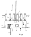
- eine schematische Draufsicht auf den Gabel-Hubwagen mit schwimmenden Palettenaufnahmen auf den Gabelzinken und Sensoren sowie einen elektronischen Kompaß, einem Schaltschrank und einer Kabeltrommel;
- Fig. 4
- eine schematische Draufsicht auf den in einer Ausgangsposition stehenden Gabel-Hubwagen, einem Querförderer und zwei versetzt stehenden Transportfahrzeuge und Referenzkanten zur Fahrwegsteuerung des Gabel-Hubwagens.
Der Hubwagen (1) weist eine integrierte Kabeltrommel (5) mit elektrischen Versorgungs- und Steuersignalkabeln (6) auf und dieses Kabel (6) ist für die Hubwagen-Querfahrt an ein Schleppkabel- (7) oder Energiekettensystem (7) angeschlossen (Fig. 4).
An den vorderen Referenzkanten (16) erfolgt dabei über die Sensoren (17) ein Abmeldesignal zur freien Weiterfahrt (S) und an den hinteren Referenzkanten (16) ein Anmeldesignal, wodurch der Hubwagen (1) vom Schaltschrank (16) wieder in der Fahrt gesteuert wird.
Während der Fahrt wird ständig die aktuelle Position des Hubwagen (1) aus dem gefahrenen Weg und der Fahrzeugdrehung berechnet. Die daraus aktuell berechnete Position des Hubwagen (1) wird mit der vorgegebenen Fahrstrecke verglichen, die Regelabweichung festgelegt und somit auch der Streckenabschnitt bestimmt, in dem sich der Hubwagen (1) gerade befindet.
Eine Schrägstellung eines zu beladenen leeren Transportfahrzeuges (F) wird durch eine Leerfahrt des Hubwagen (1) nach dem vorher beschriebenen Verfahren ermittelt und als aktuelle Fahrroute für die Beladung hinterlegt. Beim Entladen eines Transportfahrzeuges (F) werden die Konturen der Ladefläche stückweise nach Entladefortschritt abgetastet und so Zug um Zug die Schrägstellung des Transportfahrzeuges (F) ermittelt.
Claims (18)
- Satellitenfahrzeug zum Ein- und Auslagern von Paletteneinheiten bei Transportfahrzeugen, mit einem motorischen angetriebenen Hubwagen mit mehreren parallel nebeneinanderliegenden, höhenverfahrbaren und gegenüber der Palette lageveränderbaren Gabelzinken, wobei der Hubwagen (1) mit Ultraschallsensoren (17, 18) zur Fahrtrichtungmessung und -korrektur sowie einer Kabeltrommel (5) mit Energie- und Signalkabel (6) zur Antriebsstromversorgung und zum Signalaustausch sowie zur Wegmessung ausgerüstet ist, dadurch gekennzeichnet, daßmindestens zwei Gabelzinken (2) quer zur Zinken-Längsrichtung seitenverfahrbar am Hubwagen (1) gelagert sind,alle Gabelzinken (2) mit quer zur Zinken-Längsrichtung schwimmenden Palettenaufnahmen (3) ausgestattet sind,
undauch die Gabelzinken (2) mit Ultraschallsensoren (17, 18) zur Fahrtrichtungmessung und -korrektur und der Hubwagen (1) mit einem Drehratensensor (19) zur Winkelmessung ausgerüstet sind. - Satellitenfahrzeug nach Anspruch 1, dadurch gekennzeichnet, daß mehrere Gabelzinken (2) einzeln oder paarweise seitenverfahrbar vorgesehen sind.
- Satellitenfahrzeug nach Anspruch 1 oder 2, dadurch gekennzeichnet, daß am Hubwagen (1) sechs Gabelzinken (2) vorgesehen sind, von denen die beiden äußeren Gabelzinken (2) feststehend und die vier dazwischen liegenden Gabelzinken (2) einzeln oder paarweise in beide Querrichtungen (Q) seitenverfahrbar sind.
- Satellitenfahrzeug nach einem der Ansprüche 1 bis 3, dadurch gekennzeichnet, daß die seitenverfahrbaren Gabelzinken (2) elektromotorisch, pneumatisch oder hydraulisch querverstellbar sind.
- Satellitenfahrzeug nach einem der Ansprüche 1 bis 3, dadurch gekennzeichnet, daß die Gabelzinken (2) mit quer zur Zinken-Längsrichtung linear begrenzt hin- und herfahrbaren, schwimmenden Palettenaufnahmen (3) mit Mittenzentrierungen ausgestattet sind.
- Satellitenfahrzeug nach einem der Ansprüche 1 bis 5, dadurch gekennzeichnet, daß die Palettenaufnahmen (3) von Linearbausteinen und die Mittenzentrierungen von Rückholgliedern, wie Rückholfedern, Elektro- oder Druckmitteltrieben, gebildet sind.
- Satellitenfahrzeug nach einem der Ansprüche 1 bis 6, dadurch gekennzeichnet, daß jeder Gabelzinken (2) am vorderen und hinteren Ende einen schwimmenden Linearbaustein (3) aufweist.
- Satellitenfahrzeug nach einem der Ansprüche 1 bis 7, gekennzeichnet durch einen das Satellitenfahrzeug (1) in mehrere Beladepositionen und Paletteneinheiten (P) in die Übergabeposition zum Satellitenfahrzeug (1) transportierenden Querförderer (4), wie Plattenband-, Ketten- oder Gurtförderer.
- Satellitenfahrzeug nach einem der Ansprüche 1 bis 8, dadurch gekennzeichnet, daß der Hubwagen (1) eine integrierte Kabeltrommel (5) mit elektrischen Versorgungs- und Steuersignalkabeln (6) aufweist und dieses Kabel (6) für die Hubwagen-Querfahrt an ein Schleppkabel- oder Energiekettensystem (7) angeschlossen ist.
- Satellitenfahrzeug nach einem der Ansprüche 1 bis 9, dadurch gekennzeichnet, daß der Hubwagen (1) einen mittigen Antriebsmotor (8) zum Antrieb von vier jeweils paarweise beiderseits des Antriebsmotors (8) angeordnete Laufräder (9, 10) aufweist, dabei die beiden inneren Laufräder (9) über eine Antriebsachse (11) mit dem Antriebsmotor (8) verbunden und das innere und äußere Laufrad (9, 10) - Laufradpaar- jeweils durch eine Kardanwelle (12) gekuppelt ist und alle vier Laufräder (9, 10) gemeinsam um einen Drehschemel (13) des Hubwagens (1) zum Lenken verdrehbar sind.
- Satellitenfahrzeug nach einem der Ansprüche 1 bis 10, dadurch gekennzeichnet, daß der Hubwagen (1) einen integrierten Schaltschrank (14) für eine direkte Signalverarbeitung aufweist, der bei Mitten- oder Schrägversatz der Transportfahrzeuge (F) zum Ladetor den von seitlich vor dem Ladetor angebrachten Ultraschallsensoren (20) in Verbindung mit Referenzkanten (16, 16a) gemessenen Versatz als Signal zur Fahrtrichtungskorrektur des Hubwagens (1) erhält.
- Satellitenfahrzeug nach einem der Ansprüche 1 bis 11, dadurch gekennzeichnet, daß zur Navigation des Satellitenfahrzeuges (1) der Hubwagen (1) und die Gabelzinken (2) mit seitlichen Ultraschallsensoren (17) für die Geradfahrmessung, der Hubwagen (1) mit einem in Fahrtrichtung (R) wirkenden Ultraschallsensor (18) für die Fahrt-Tiefenmessung und einem Drehratensensor (19) zur Winkelmessung ausgestaltet ist.
- Satellitenfahrzeug nach einem der Ansprüche 1 bis 12, dadurch gekennzeichnet, daß seitliche, in die Ladeöffnung des Transportfahrzeuges (F) einschwenkbare Referenzkanten (16a) als bewegliche Einfahrhilfen für das Transportfahrzeug (F) vorgesehen sind.
- Satelittenfahrzeug nach einem der Ansprüche 1 bis 13, dadurch gekennzeichnet, daß die Gabelzinken (2) mechanische, herausklappbare Tastanschläge aufweisen, um kürze Paletten (P) mit der Vorderkante der Gabelzinken (2) abschließen zu lassen.
- Satelittenfahrzeug nach einem der Ansprüche 1 bis 14, dadurch gekennzeichnet, daß der Hubwagen (12) zwei Kabeltrommeln (5) mit Stahlseil aufweist und dabei die Energieeinspeisung auf dünnere Versorgungskabel (6) aufgeteilt ist und die Kabel (6) durch Stillstandsmotore beim Auf- und Abwickeln straff gehalten werden.
- Satelittenfahrzeug nach einem der Ansprüche 1 bis 15, dadurch gekennzeichnet, daß die beiden äußeren Räderpaare (10) des Hubwagens (1) mit je einem Antrieb (8) gekuppelt sind.
- Satelittenfahrzeug nach einem der Ansprüche 1 bis 16, dadurch gekennzeichnet, daß die Schleppkabelbewegung von einem Reibradantrieb unterstützt ist, wobei der Start und Stop dieser Bewegung durch das schräggestellte Kabel (6) über einen davon betätigten Schalter erfolgt.
- Satelittenfahrzeug nach einem der Ansprüche 1 bis 17, dadurch gekennzeichnet, daß die Drehlagerung der Antriebs- und Stützräder (9, 10) durch Hydraulik- oder Federdrucke den Bodenverhältnissen anpaßbar im Hubwagen (1) vertikal verschiebbar vorgesehen ist.
Applications Claiming Priority (3)
| Application Number | Priority Date | Filing Date | Title |
|---|---|---|---|
| DE19814941 | 1998-04-03 | ||
| DE19814941A DE19814941A1 (de) | 1998-04-03 | 1998-04-03 | Satellitenfahrzeug zum Ein- und Auslagern von Paletteneinheiten bei Transportfahrzeugen |
| PCT/EP1999/002125 WO1999051513A1 (de) | 1998-04-03 | 1999-03-29 | Satellittenfahrzeug zum ein- und auslagern von paletteneinheiten bei transportfahrzeugen |
Publications (2)
| Publication Number | Publication Date |
|---|---|
| EP0996581A1 EP0996581A1 (de) | 2000-05-03 |
| EP0996581B1 true EP0996581B1 (de) | 2004-05-19 |
Family
ID=7863468
Family Applications (1)
| Application Number | Title | Priority Date | Filing Date |
|---|---|---|---|
| EP99914554A Expired - Lifetime EP0996581B1 (de) | 1998-04-03 | 1999-03-29 | Satellitenfahrzeug zum ein- und auslagern von paletteneinheiten bei transportfahrzeugen |
Country Status (5)
| Country | Link |
|---|---|
| US (1) | US6241453B1 (de) |
| EP (1) | EP0996581B1 (de) |
| AT (1) | ATE267128T1 (de) |
| DE (1) | DE19814941A1 (de) |
| WO (1) | WO1999051513A1 (de) |
Families Citing this family (27)
| Publication number | Priority date | Publication date | Assignee | Title |
|---|---|---|---|---|
| DE19859445C2 (de) * | 1998-12-22 | 2001-01-11 | Asm Automation Sensorik Messte | Meßseil-Wegsensor mit einem Längsantrieb für die Seiltrommel |
| EP1231163A1 (de) * | 2001-02-12 | 2002-08-14 | Beumer Maschinenfabrik GmbH & Co. KG | Stückgut-Lagereinrichtung |
| EP1293472A3 (de) * | 2001-09-18 | 2005-05-04 | Wolfgang Janssen | Flurförderzeug mit Sicherheitseinrichtung |
| MXPA04007841A (es) * | 2002-02-12 | 2005-06-17 | Tynecat Technologies Pty Ltd | Carretilla de transporte conducible. |
| TW200540089A (en) * | 2004-05-03 | 2005-12-16 | Webb Int Co Jerwis B | Automatic transport loading system and method |
| US8210791B2 (en) * | 2004-05-03 | 2012-07-03 | Jervis B. Webb Company | Automatic transport loading system and method |
| US8075243B2 (en) * | 2004-05-03 | 2011-12-13 | Jervis B. Webb Company | Automatic transport loading system and method |
| US7980808B2 (en) * | 2004-05-03 | 2011-07-19 | Jervis B. Webb Company | Automatic transport loading system and method |
| US8192137B2 (en) * | 2004-05-03 | 2012-06-05 | Jervis B. Webb Company | Automatic transport loading system and method |
| US8260454B2 (en) | 2007-02-16 | 2012-09-04 | Boomerang Systems, Inc. | Automated storage system |
| ITMI20070326A1 (it) * | 2007-02-20 | 2008-08-21 | Ocme Srl | Veicolo a guida automatica con gruppo di sollevamento multipallet perfezionato |
| DE102007029887A1 (de) * | 2007-06-28 | 2009-01-02 | Still Wagner Gmbh | Flurförderzeug, Lagersystem und Verfahren zur Zielfindung in Lagersystemen |
| JP2009259302A (ja) * | 2008-04-11 | 2009-11-05 | Sony Corp | 記録媒体チェンジャー |
| EP2184254B1 (de) * | 2008-11-11 | 2013-01-09 | Deutsche Post AG | Gabelstapler mit Führungs- und Kollisionswarnvorrichtung |
| CN102314302A (zh) * | 2011-06-07 | 2012-01-11 | 百度在线网络技术(北京)有限公司 | 一种用于对用户设备进行状态锁定的方法与设备 |
| DE102012008716A1 (de) * | 2012-05-03 | 2013-11-07 | Itw Packaging Systems Group Gmbh | Vorrichtung zum Umreifen von Packstücken |
| US20150251885A1 (en) * | 2014-03-07 | 2015-09-10 | Signs365 | Variable fork attachment for hi-lo vehicle |
| US9561941B1 (en) | 2015-03-30 | 2017-02-07 | X Development Llc | Autonomous approach and object pickup |
| CA2926430C (en) | 2015-04-08 | 2023-09-19 | Joseph Andrew Weiss | Load centering devices and methods for a material handling vehicle |
| CN107364678A (zh) * | 2016-05-24 | 2017-11-21 | 山西东械自动化科技有限公司 | 一种多功能搬运小车 |
| CN109250415A (zh) * | 2018-11-15 | 2019-01-22 | 深圳市佳顺智能机器人股份有限公司 | 一种与agv对接的浮动装置及传输平台 |
| DE102019107702B3 (de) | 2019-03-26 | 2020-05-28 | Signode Industrial Group Llc | Verfahren zur Anordnung eines Kantenschutzmittels an einem Packstück in einer Vorrichtung zum Umreifen von Packstücken sowie Vorrichtung zum Umreifen von Packstücken |
| DE102019114316A1 (de) * | 2019-05-28 | 2020-12-03 | Heinz Buse | Übergabestation zum Verladen von Warenpaletten in einem Logistiksystem und Logistiksystem |
| CN110980074A (zh) * | 2019-11-14 | 2020-04-10 | 安徽驿星智能物流装备制造有限公司 | 一种低功耗自换向升降小车 |
| CN111532638A (zh) * | 2020-04-15 | 2020-08-14 | 上海韬谱物流设备有限公司 | 无人仓系统 |
| CN112194049B (zh) * | 2020-09-30 | 2022-06-21 | 杭州海康机器人技术有限公司 | 一种带有伸缩臂机构的叉车 |
| TWI833384B (zh) * | 2022-10-11 | 2024-02-21 | 群亮力科技股份有限公司 | 倉儲系統的運載車及其浮板組件 |
Family Cites Families (8)
| Publication number | Priority date | Publication date | Assignee | Title |
|---|---|---|---|---|
| DE2909667C2 (de) * | 1979-03-12 | 1985-02-14 | Jungheinrich Unternehmensverwaltung Kg, 2000 Hamburg | Elektrischer Antriebs-Steuerteil für lenkbare Fahrzeuge, insbesondere Hublader |
| DE2930569A1 (de) | 1979-07-27 | 1981-02-19 | Friedhelm Krups Fa | Beschickungsanlage fuer ein lager |
| JPS59112312A (ja) * | 1982-12-20 | 1984-06-28 | Nippon Yusoki Co Ltd | 無人搬送車の誘導帯 |
| US4595331A (en) | 1983-12-29 | 1986-06-17 | Adolph Coors Company | Automated railcar loader and method |
| DE3702918C2 (de) * | 1987-02-02 | 1994-11-17 | Kaup Gmbh & Co Kg | Vorbaugerät für einen Gabelstapler mit sechs an einem Tragkörper horizontal verschiebbar gelagerten Gabelzinken |
| FR2725436A1 (fr) * | 1994-10-05 | 1996-04-12 | Ba Systemes | Installation de chargement/dechargement pour engin automoteur a deplacement guide |
| DE19613386A1 (de) * | 1996-04-03 | 1997-10-09 | Fiat Om Carrelli Elevatori | Flurförderzeug, das wahlweise manuell oder automatisch betreibbar ausgebildet ist |
| DE29620342U1 (de) * | 1996-11-22 | 1998-03-19 | Westfalia Wst Systemtechnik | Satellitenfahrzeug |
-
1998
- 1998-04-03 DE DE19814941A patent/DE19814941A1/de not_active Ceased
-
1999
- 1999-03-29 AT AT99914554T patent/ATE267128T1/de not_active IP Right Cessation
- 1999-03-29 WO PCT/EP1999/002125 patent/WO1999051513A1/de active IP Right Grant
- 1999-03-29 EP EP99914554A patent/EP0996581B1/de not_active Expired - Lifetime
- 1999-03-29 US US09/424,974 patent/US6241453B1/en not_active Expired - Fee Related
Also Published As
| Publication number | Publication date |
|---|---|
| ATE267128T1 (de) | 2004-06-15 |
| EP0996581A1 (de) | 2000-05-03 |
| DE19814941A1 (de) | 1999-10-07 |
| US6241453B1 (en) | 2001-06-05 |
| WO1999051513A1 (de) | 1999-10-14 |
Similar Documents
| Publication | Publication Date | Title |
|---|---|---|
| EP0996581B1 (de) | Satellitenfahrzeug zum ein- und auslagern von paletteneinheiten bei transportfahrzeugen | |
| EP2100831B1 (de) | Transportwagen für Paletten und Transportsystem | |
| AT509305B1 (de) | Fahrerlose transporteinrichtung | |
| EP2607292B1 (de) | System zum Transport von auf Hilfsmitteln angeordneten Gütern | |
| EP2681137B1 (de) | Vorrichtung und verfahren zum definierten zwischenlagern und kommissionieren produzierter waren gleicher art aber unterschiedlicher grösse | |
| DE202014006562U1 (de) | Fördereinheit und Fördersystem zum Fördern von Ladungsträgern | |
| DE102006039382A1 (de) | Stückgut-Transportvorrichtung für ein Stückgut-Lagersystem, und Verfahren zum Betreiben der Vorrichtung | |
| EP2558384A1 (de) | Lager- und transportsystem für transportbehälter | |
| EP3426593B2 (de) | Fahrerloses transportfahrzeug | |
| DE60119705T2 (de) | Verfahren und vorrichtung zur handhabung von grossrollen | |
| EP0916615B1 (de) | Fahrerloses, z.B. frei navigierendes Transportfahrzeug zum Handhaben von Lasten | |
| DE102020119276A1 (de) | Radarmstapler, vorzugsweise als AGV | |
| EP3693325B1 (de) | Anliefersystem | |
| EP1422169B1 (de) | Lagersystem mit schienengebundenen Fahrzeugen zur Aufnahme und Abgabe von Lagergut | |
| DE19503198C1 (de) | Vorrichtung für das seitliche Be- und Entladen von Fahrzeugen | |
| DE102009026701A1 (de) | Verfahren zum gleichzeitigen Beladen einer Ladefläche eines Lastfahrzeugs mit einer Vielzahl von Güterpaletten und Lademaschine dafür | |
| EP3702303A1 (de) | Übergabesystem | |
| DE3328241C2 (de) | Förderfahrzeug | |
| DE102014208953A1 (de) | Autonomes fahrerloses Transportfahrzeug und Transportsystem | |
| DE102016125157A1 (de) | Flurförderzeug zum Drehen von Paletten | |
| EP3693326A2 (de) | Überführungsanordnung | |
| DE2920099C2 (de) | Verfahren und Vorrichtung zum Lenken eines Flurförderers | |
| EP3640196B1 (de) | Autonomes, bodengebundenes flurförderzeug und verfahren zum be- und/oder entladen einer ladeeinheit mit einem solchen flurförderzeug | |
| DE2931241A1 (de) | Vorrichtung zum transport von ladeeinheiten | |
| WO2020239376A1 (de) | System umfassend einen routenzug mit mindestens einen routenzuganhänger und mindestens einen von dem routenzuganhänger aufnehmbaren wagen |
Legal Events
| Date | Code | Title | Description |
|---|---|---|---|
| PUAI | Public reference made under article 153(3) epc to a published international application that has entered the european phase |
Free format text: ORIGINAL CODE: 0009012 |
|
| AK | Designated contracting states |
Kind code of ref document: A1 Designated state(s): AT BE CH ES FR GB GR IT LI LU NL PT |
|
| 17P | Request for examination filed |
Effective date: 20000324 |
|
| GRAP | Despatch of communication of intention to grant a patent |
Free format text: ORIGINAL CODE: EPIDOSNIGR1 |
|
| GRAS | Grant fee paid |
Free format text: ORIGINAL CODE: EPIDOSNIGR3 |
|
| GRAA | (expected) grant |
Free format text: ORIGINAL CODE: 0009210 |
|
| AK | Designated contracting states |
Kind code of ref document: B1 Designated state(s): AT BE CH ES FR GB GR IT LI LU NL PT |
|
| PG25 | Lapsed in a contracting state [announced via postgrant information from national office to epo] |
Ref country code: NL Free format text: LAPSE BECAUSE OF FAILURE TO SUBMIT A TRANSLATION OF THE DESCRIPTION OR TO PAY THE FEE WITHIN THE PRESCRIBED TIME-LIMIT Effective date: 20040519 Ref country code: IT Free format text: LAPSE BECAUSE OF FAILURE TO SUBMIT A TRANSLATION OF THE DESCRIPTION OR TO PAY THE FEE WITHIN THE PRESCRIBED TIME-LIMIT;WARNING: LAPSES OF ITALIAN PATENTS WITH EFFECTIVE DATE BEFORE 2007 MAY HAVE OCCURRED AT ANY TIME BEFORE 2007. THE CORRECT EFFECTIVE DATE MAY BE DIFFERENT FROM THE ONE RECORDED. Effective date: 20040519 |
|
| REG | Reference to a national code |
Ref country code: GB Ref legal event code: FG4D Free format text: NOT ENGLISH |
|
| REG | Reference to a national code |
Ref country code: CH Ref legal event code: EP |
|
| PG25 | Lapsed in a contracting state [announced via postgrant information from national office to epo] |
Ref country code: GR Free format text: LAPSE BECAUSE OF FAILURE TO SUBMIT A TRANSLATION OF THE DESCRIPTION OR TO PAY THE FEE WITHIN THE PRESCRIBED TIME-LIMIT Effective date: 20040819 |
|
| PG25 | Lapsed in a contracting state [announced via postgrant information from national office to epo] |
Ref country code: ES Free format text: LAPSE BECAUSE OF FAILURE TO SUBMIT A TRANSLATION OF THE DESCRIPTION OR TO PAY THE FEE WITHIN THE PRESCRIBED TIME-LIMIT Effective date: 20040830 |
|
| GBT | Gb: translation of ep patent filed (gb section 77(6)(a)/1977) |
Effective date: 20040809 |
|
| REG | Reference to a national code |
Ref country code: CH Ref legal event code: NV Representative=s name: NOVAGRAAF INTERNATIONAL SA |
|
| NLV1 | Nl: lapsed or annulled due to failure to fulfill the requirements of art. 29p and 29m of the patents act | ||
| ET | Fr: translation filed | ||
| PLBE | No opposition filed within time limit |
Free format text: ORIGINAL CODE: 0009261 |
|
| STAA | Information on the status of an ep patent application or granted ep patent |
Free format text: STATUS: NO OPPOSITION FILED WITHIN TIME LIMIT |
|
| PG25 | Lapsed in a contracting state [announced via postgrant information from national office to epo] |
Ref country code: LU Free format text: LAPSE BECAUSE OF NON-PAYMENT OF DUE FEES Effective date: 20050329 Ref country code: GB Free format text: LAPSE BECAUSE OF NON-PAYMENT OF DUE FEES Effective date: 20050329 Ref country code: AT Free format text: LAPSE BECAUSE OF NON-PAYMENT OF DUE FEES Effective date: 20050329 |
|
| PG25 | Lapsed in a contracting state [announced via postgrant information from national office to epo] |
Ref country code: LI Free format text: LAPSE BECAUSE OF NON-PAYMENT OF DUE FEES Effective date: 20050331 Ref country code: CH Free format text: LAPSE BECAUSE OF NON-PAYMENT OF DUE FEES Effective date: 20050331 Ref country code: BE Free format text: LAPSE BECAUSE OF NON-PAYMENT OF DUE FEES Effective date: 20050331 |
|
| 26N | No opposition filed |
Effective date: 20050222 |
|
| BERE | Be: lapsed |
Owner name: *WESTFALIA-WST-SYSTEMTECHNIK G.M.B.H. & CO. K.G. Effective date: 20050331 |
|
| REG | Reference to a national code |
Ref country code: CH Ref legal event code: PL |
|
| GBPC | Gb: european patent ceased through non-payment of renewal fee |
Effective date: 20050329 |
|
| PG25 | Lapsed in a contracting state [announced via postgrant information from national office to epo] |
Ref country code: FR Free format text: LAPSE BECAUSE OF NON-PAYMENT OF DUE FEES Effective date: 20051130 |
|
| REG | Reference to a national code |
Ref country code: FR Ref legal event code: ST Effective date: 20051130 |
|
| BERE | Be: lapsed |
Owner name: *WESTFALIA-WST-SYSTEMTECHNIK G.M.B.H. & CO. K.G. Effective date: 20050331 |
|
| PG25 | Lapsed in a contracting state [announced via postgrant information from national office to epo] |
Ref country code: PT Free format text: LAPSE BECAUSE OF NON-PAYMENT OF DUE FEES Effective date: 20041019 |