EP0993804B1 - Système pour la poursuite d'un objet - Google Patents
Système pour la poursuite d'un objet Download PDFInfo
- Publication number
- EP0993804B1 EP0993804B1 EP99308114A EP99308114A EP0993804B1 EP 0993804 B1 EP0993804 B1 EP 0993804B1 EP 99308114 A EP99308114 A EP 99308114A EP 99308114 A EP99308114 A EP 99308114A EP 0993804 B1 EP0993804 B1 EP 0993804B1
- Authority
- EP
- European Patent Office
- Prior art keywords
- signals
- responsive
- amplitude
- field
- article
- Prior art date
- Legal status (The legal status is an assumption and is not a legal conclusion. Google has not performed a legal analysis and makes no representation as to the accuracy of the status listed.)
- Expired - Lifetime
Links
Images
Classifications
-
- A—HUMAN NECESSITIES
- A61—MEDICAL OR VETERINARY SCIENCE; HYGIENE
- A61B—DIAGNOSIS; SURGERY; IDENTIFICATION
- A61B5/00—Measuring for diagnostic purposes; Identification of persons
- A61B5/06—Devices, other than using radiation, for detecting or locating foreign bodies ; determining position of probes within or on the body of the patient
-
- A—HUMAN NECESSITIES
- A61—MEDICAL OR VETERINARY SCIENCE; HYGIENE
- A61B—DIAGNOSIS; SURGERY; IDENTIFICATION
- A61B34/00—Computer-aided surgery; Manipulators or robots specially adapted for use in surgery
- A61B34/20—Surgical navigation systems; Devices for tracking or guiding surgical instruments, e.g. for frameless stereotaxis
-
- A—HUMAN NECESSITIES
- A61—MEDICAL OR VETERINARY SCIENCE; HYGIENE
- A61B—DIAGNOSIS; SURGERY; IDENTIFICATION
- A61B5/00—Measuring for diagnostic purposes; Identification of persons
- A61B5/06—Devices, other than using radiation, for detecting or locating foreign bodies ; determining position of probes within or on the body of the patient
- A61B5/061—Determining position of a probe within the body employing means separate from the probe, e.g. sensing internal probe position employing impedance electrodes on the surface of the body
- A61B5/062—Determining position of a probe within the body employing means separate from the probe, e.g. sensing internal probe position employing impedance electrodes on the surface of the body using magnetic field
-
- A—HUMAN NECESSITIES
- A61—MEDICAL OR VETERINARY SCIENCE; HYGIENE
- A61B—DIAGNOSIS; SURGERY; IDENTIFICATION
- A61B34/00—Computer-aided surgery; Manipulators or robots specially adapted for use in surgery
- A61B34/20—Surgical navigation systems; Devices for tracking or guiding surgical instruments, e.g. for frameless stereotaxis
- A61B2034/2046—Tracking techniques
- A61B2034/2051—Electromagnetic tracking systems
-
- A—HUMAN NECESSITIES
- A61—MEDICAL OR VETERINARY SCIENCE; HYGIENE
- A61B—DIAGNOSIS; SURGERY; IDENTIFICATION
- A61B90/00—Instruments, implements or accessories specially adapted for surgery or diagnosis and not covered by any of the groups A61B1/00 - A61B50/00, e.g. for luxation treatment or for protecting wound edges
- A61B90/08—Accessories or related features not otherwise provided for
- A61B2090/0807—Indication means
- A61B2090/0808—Indication means for indicating correct assembly of components, e.g. of the surgical apparatus
-
- A—HUMAN NECESSITIES
- A61—MEDICAL OR VETERINARY SCIENCE; HYGIENE
- A61B—DIAGNOSIS; SURGERY; IDENTIFICATION
- A61B90/00—Instruments, implements or accessories specially adapted for surgery or diagnosis and not covered by any of the groups A61B1/00 - A61B50/00, e.g. for luxation treatment or for protecting wound edges
- A61B90/08—Accessories or related features not otherwise provided for
- A61B2090/0807—Indication means
- A61B2090/0809—Indication of cracks or breakages
Definitions
- the present invention relates generally to apparatus for generating and detecting electromagnetic fields, and specifically to non-contact, electromagnetic devices for tracking the position and orientation of an object, and associated disclosed method, not forming a part of the invention.
- Non-contact electromagnetic tracking systems are well known in the art, with a wide range of applications.
- U.S. patent 4,054,881 describes a tracking system using three coils to generate electromagnetic fields in the vicinity of an object being tracked.
- the fields generated by these three coils are distinguished from one another by open loop multiplexing of time, frequency or phase.
- the signal currents flowing in three orthogonal sensor coils are used to determine the object's position, based on an iterative method of computation.
- a sensor coil is placed in the catheter and generates signals in response to externally applied magnetic fields.
- the magnetic fields are generated by three radiator coils, fixed to an external reference frame in known, mutually spaced locations.
- the amplitudes of the signals generated in response to each of the radiator coil fields are detected and used to compute the location of the sensor coil.
- Each radiator coil is preferably driven by driver circuitry to generate a field at a known frequency, distinct from that of other radiator coils, so that the signals generated by the sensor coil may be separated by frequency into components corresponding to the different radiator coils.
- This system uses a plurality of sensor coils adjacent to a locatable site in the catheter, for example near its distal end, and a plurality of radiator coils fixed in an external reference frame. These coils generate signals in response to magnetic fields generated by the radiator coils, which signals allow for the computation of six location and orientation coordinates.
- the radiator coils preferably operate simultaneously at different frequencies, for example at 1000, 2000 and 3000 Hz, respectively.
- the above tracking systems rely on separation of position-responsive signals into components, most typically frequency components, wherein each such component is assumed to correspond uniquely to a single radiator coil, in a known position, radiating a magnetic field having a regular, well-defined spatial distribution.
- each such component is assumed to correspond uniquely to a single radiator coil, in a known position, radiating a magnetic field having a regular, well-defined spatial distribution.
- the magnetic fields generated in this vicinity by the radiator coils are distorted.
- the radiator coil's magnetic field may generate eddy currents in such an article, and the eddy currents will then cause a parasitic magnetic field to be radiated.
- parasitic fields and other types of distortion can lead to errors in determining the position of the object being tracked.
- WO 97/29679 there is shown an endoscope with sensors that generate signals responsive to a magnetic field in order to determine positions and/or orientation of the endoscope.
- the sensors are located remote from interference causing structures in the endoscope.
- the position determination is corrected so as to account for disturbances of an energy field used in tracking the object due to metal or other field-responsive articles in the vicinity of the object being tracked.
- such disturbances are detected, so as to alert a user of the system that the accuracy of position determination may be compromised.
- the energy field comprises a magnetic field, which causes position-responsive electrical signals to be generated in one or more coils associated with the object being tracked, for example a catheter or other medical probe.
- the present invention relies on the fact that parasitic magnetic fields, generated by metal or other field-responsive articles that receive and re-radiate energy from a radiator coil magnetic field are typically at the same frequency as the radiator coil field, but are shifted in phase relative thereto.
- the phase shift and the amplitudes of the parasitic fields generally depend on properties of the article, including dielectric constant, magnetic permeability and geometrical shape.
- the article introduced into the magnet field is substantially magnetizable, i.e., its permeability is significantly different from the permeability of air, the lines of magnetic field in the vicinity of the article are generally distorted. Distortion of this type does not, however, substantially affect the phase of the magnetic field.
- an object tracking system comprises one or more sensor coils adjacent to a locatable point on an object being tracked, and one or more radiator coils, which generate magnetic fields when driven by electrical currents at respective driving frequencies in a vicinity of the object.
- each of the radiator coils has its own frequency, which is different from the frequencies of all the other radiator coils.
- two or more of the radiator coils may share a common frequency, and may be time-multiplexed so that only one of the two or more coils is driven to generate a magnetic field at any given time.
- the sensor coils generate electrical signals responsive to the magnetic fields, which signals are received by signal processing circuitry and analyzed by a computer or other processor.
- the signals typically include position signal components responsive to the magnetic fields generated by the radiator coils at their respective driving frequencies, and parasitic signal components responsive to parasitic magnetic fields generated due to the article.
- the computer processes the signals to identify the parasitic components, preferably using a phase-sensitive method, as described below, and uses the position signal components to determine the position of the object.
- the signals due to the magnetic field generated by each of the radiator coils are first detected in the absence of any articles that could cause parasitic signal components to be generated.
- Baseline phases of the signals at each of the radiator coil frequencies which are substantially independent of the position of the object relative to the radiator coils, are then determined relative to the phase of the current driving the respective radiator coil.
- an article that generates parasitic magnetic fields is introduced into the vicinity of the object, at least some signal components generated by the sensor coils in response to the parasitic fields will generally be shifted in phase relative to the pre-determined baseline phase.
- the phase shift of the signals due to the parasitic signal components is detected and may be used to indicate that the position of the object determined by the computer may be inaccurate due to the presence of the article in the object's vicinity.
- the object while a metal or other field-responsive article is being moved into the vicinity of the object being tracked, the object is preferably held still. Changes in the amplitude and phase of the signals received from the sensor coils are then known to be associated with distortions of the magnetic field due to the article. These changes are detected and used in assessing the effect of the distortions on the determination of the object's position coordinates.
- the detected changes may be used to measure the phase shifts of the parasitic fields, relative to the radiator coil fields.
- these phase shifts will be generally constant, independent of the position and orientation of the field-responsive article, for example, if the article is substantially symmetrical.
- the phase shift of the parasitic fields will be close to 90°, generally independent of the position and orientation of the article.
- the dependence of the phase shift on position and orientation can be determined empirically in each case.
- a characteristic of the article such as the distortion of the magnetic field that the article induces or the effect of the article on the determination of the object's coordinates, is known, for example based on prior measurement.
- the known characteristic may be used to correct the determination of the coordinates, as described below.
- the signals generated by the sensor coils are detected using a harmonic detection method, more preferably with the detection frequency synchronized with the frequencies of the radiator coils.
- Signal components that are out of phase with the baseline phase are eliminated from the sampled signal, for example using phase-sensitive signal correlation or other methods known in the art, thereby substantially removing at least some of the parasitic signal components and improving the accuracy of position determination in the presence of the metal or other field-responsive article.
- phase shifts of the parasitic fields are known, having been measured as described above, for example, then the known phase shifts may be used in analyzing the signals so as to remove at least a portion of the parasitic signal components therefrom.
- a method for tracking an object using an energy field, in the presence of interference due to introduction of an article responsive to the field, in the vicinity of the object may include:
- Determining the characteristic includes determining a phase shift of the signals responsive to the second energy field with respect to the signals responsive to the first energy field.
- the characteristic is not determined from measurements made at the location.
- Determining spatial coordinates includes determining an amplitude of the signals generated at a location of the object; processing the amplitude to find a corrected amplitude, using the determined characteristic; and calculating the coordinates based on the corrected amplitude.
- determining the characteristic of the induced energy fields includes receiving a first signal responsive to the energy field in the absence of the field-responsive article; introducing the article into the vicinity of the object; receiving a second signal responsive to the energy field in the presence of the article; and processing the first and second signals to determine the characteristic.
- processing the first and second signals includes finding a first amplitude and a first phase of the first signal; finding a second amplitude and a second phase of the second signal; and determining a phase shift associated with the induced field, based on the first and second amplitudes and the first and second phases.
- determining spatial coordinates may include measuring an uncorrected amplitude and an uncorrected phase of the signals received at one of the plurality of locations of the object; finding a corrected amplitude, using the phase shift associated with the induced field; and calculating the coordinates based on the corrected amplitude.
- the disclosed method includes detecting a malfunction in a system for tracking the object by finding a variability in one or more of the first and second phases.
- determining the spatial coordinates of the object includes estimating an error bound on the coordinates in the presence of the article.
- producing the energy fields includes producing magnetic fields
- receiving the signals includes receiving electrical signals which are generated responsive to the magnetic field.
- an object tracking system including:
- circuitry detecting a malfunction in the system by finding a variability in the phase shift.
- circuitry notifying a user of the system that the article has been introduced, based on the detected interference.
- the circuitry determines an error bound on the coordinates, based on the detected interference.
- the energy field includes a magnetic field
- the signals include electrical currents generated responsive to the magnetic field.
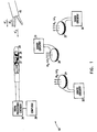
- Fig. 1 schematically illustrates a system 10 for tracking a probe 20, such as a catheter for medical use, in accordance with preferred embodiment of the present invention.
- system 10 comprises a plurality of radiator coils 22, 24 and 26. These coils generate respective magnetic fields H 1 , H 2 and H 3 , at respective frequencies ⁇ 1 , ⁇ 2 and ⁇ 3 , in the vicinity of probe 20.
- the probe includes sensor coils 27, 28 and 29, which generate electrical current signals in response to the magnetic fields. These signals comprise components at frequencies ⁇ 1 , ⁇ 2 and ⁇ 3 , whose respective amplitudes are dependent on the position and orientation of probe 20.
- System 10 further comprises driver circuitry 30, 32 and 33, coupled to each of the radiator coils, which drives coils 22, 24 and 26 at the respective driving frequencies ⁇ 1 , ⁇ 2 and ⁇ 3 .
- the signals generated by sensor coils 27, 28 and 29 are preferably received and processed by signal processing circuitry 34 and then used by computer 36 to calculate position and orientation coordinates of probe 20.
- Fig. 1 shows three radiator coils 22, 24 and 26 and three sensor coils 27, 28 and 29 in a probe 20. It will be understood, however, that the present invention is equally applicable to tracking systems comprising one, two, four or more radiator coils and one, two or more sensor coils. For six-dimensional tracking of probe 20 (three degrees of translation and three degrees of rotation), however, system 10 preferably include a total of six coils, counting both the radiator and sensor coils. Furthermore, although in preferred embodiments of the present invention are described here with reference to frequency-multiplexing of the radiator coils, the principles of the invention may similarly be applied to coils that are time-multiplexed or driven using other methods known in the art to distinguish their respective magnetic fields one from another. The present invention may be used in tracking other types of objects, as well.
- the signals generated by sensor coils 27, 28 and 29 at frequency ⁇ 1 are proportional to the amplitude of the time derivative of the projection of field H 1 at probe 20 along the respective axes of the sensor coils.
- the signals generated at frequencies ⁇ 2 and ⁇ 3 are similarly proportional to the projections of H 2 and H 3 .
- Parasitic effects that may arise due to mutual inductance among the radiator coils are preferably substantially eliminated, as disclosed, for example, in PCT patent application no. PCT/IL/00100, filed March 18, 1997.
- the sensor coil signals due to the respective radiator coil field may be directly related to the sensor coil's distance from and orientation relative to the radiator coil. It will also be appreciated that in the absence of parasitic magnetic fields, such as will be described below, the phases of the signals at frequencies ⁇ 1 , ⁇ 2 and ⁇ 3 are substantially constant relative to the phases of the magnetic fields generated by radiator coils 22, 24 and 26, independent of the position and orientation of sensor coils 27, 28 and 29.
- a metal or magnetic field-responsive article for example surgical tool 40
- the article will generally receive energy from fields H 1 , H 2 and H 3 , and re-radiate parasitic magnetic fields, H ' / 1 , H ' / 2 and H ' / 3 , at frequencies ⁇ 1 , ⁇ 2 and ⁇ 3 .
- the phases of the parasitic fields will be shifted relative to the radiator coil fields by phase angles ⁇ 1 ', ⁇ 2 ' and ⁇ 3 ', respectively.
- the phases and amplitudes of the parasitic fields generally depend on properties of tool 40, including its dielectric constant, magnetic permeability, geometrical shape and orientation relative to the radiator coils.
- phase may of the parasitic fields may generally vary as a function of the tool's position and orientation, in certain cases the phases will be substantially constant, for example, when tool 40 has suitable symmetry with respect to the fields generated by coils 22, 24 and 26, or when the tool comprises material of negligible resistivity.
- the parasitic fields produced by tool 40 will cause corresponding parasitic signal components to be generated in sensor coils 27, 28 and 29, so that the total signal I(t) received from any one of the sensor coils, including both position and parasitic signal components may generally be expressed as: where A i , ⁇ i , A i ' and ⁇ i ' are the amplitude and phase of the position signal component and the parasitic signal component, respectively, at frequency ⁇ i .
- signal processing circuitry 34 and computer 36 detect and record a baseline phase of the signals received from sensor coils 27, 28 and 29 in the absence of any metal or other interfering magnetic field-responsive objects in the vicinity of probe 20.
- undisturbed phases of the position signal components may have been determined in advance for system 10 or are known based on the operation of the system.
- computer 36 may present a message to an operator of the probe, indicating that the determination of the probe's position may be inaccurate.
- the amplitudes A i ' of the parasitic signal components are measured, for example as described below, and are then used to estimate and inform the operator of an error bound on the position coordinates determined by computer 36.
- the baseline phase of the signals received from sensor coils 27, 28 and 29 will be substantially constant, in the absence of interfering objects such as tool 40. If circuitry 34 receives a signal having a variable phase, particularly a randomly variable phase, such a signal is typically indicative of a malfunction in system 10, for example, a loose connection between one of the sensor coils and the circuitry. In such a case, probe 20 should be removed and repaired.
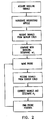
- Fig. 2 illustrates schematically a method for detecting interference due to tool 40 or due to another magnetic field-responsive article, and determining the correct position of probe 20 in the presence of such interference, in accordance with preferred embodiments of the present invention.
- normalized baseline signals are first acquired by computer 36 at each of frequencies ⁇ i in the absence of tool 40 or any other interfering article. Subsequently, after the tool is introduced into the vicinity of the probe 20, these baseline signals are compared with signals received from sensor coils 27, 28 and 29, using methods of signal correlation known in the art, for example, in order to measure the phase shifts ⁇ i '.
- the phase shifts are measured for different positions and orientations of the tool, in order to ascertain the extent to which the phase shifts ⁇ i ' vary with tool position and orientation. If the measured phase shifts are found to be generally constant (or are known to be so from previous measurement), they may be used to calculate corrected values of A i , for example, based on formula (1). The position of probe 20 is then found with sufficient accuracy even in the presence of parasitic magnetic fields due to tool 40.
- probe 20 is held immobile while tool 40 is being moved into its vicinity. Any changes in the amplitudes and phases of the signals received from sensor coils 27, 28 and 29 are then known to be associated with distortions of the magnetic field due to the article. These changes are detected and used in measuring the effect of the distortions on the determination of the probe's position coordinates.
- the detected changes may be used to measure the phase shifts ⁇ ' / i of the parasitic fields, relative to the radiator coil fields.
- the phase shifts ⁇ ' / i of the re-radiated fields will not change significantly as the tool is moved. Therefore, one measurement of ⁇ ' / i , made while probe 20 is held in any desired position and tool 40 is in any other suitable position in a vicinity of the probe, may be sufficient for calculating values of A i that are substantially corrected for the effect of the re-radiated fields, at all other positions of interest of probe 20 and tool 40.
- the re-radiated fields are the dominant source of magnetic field distortion due to tool 40. Distortion of the lines of magnetic field due to the magnetic permeability of tool 40 gives rise to parasitic magnetic field components that are generally in phase with fields H 1 , H 2 and H 3 , and are therefore more difficult to quantify and correct for.
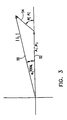
- Fig. 3 is a vector diagram illustrating the method described above for separating the position and parasitic signal components.
- Signal vector 50 having amplitude
- Vector 50 is the vector sum of position signal component vector 52 and parasitic signal component vector 54.
- Position signal component 52 has amplitude A i and known, substantially constant phase ⁇ i , which is arbitrarily assigned the value zero, without loss of generality.
- phase ⁇ i ' (for the cases described above, in which ⁇ i ' can be considered to be substantially constant) of parasitic signal component 54 is also known, for example having been measured as described above, then a triangle defined by vectors 50, 52 and 54 is completely determined, since all its angles ( ⁇ i , ⁇ i ' and ⁇ i total ) and one of its sides (
- Fig. 3 assumes that the phases of the parasitic signal components are shifted relative to the position signal components.
- tool 40 or another magnetic field-responsive article in the vicinity of probe 20 has magnetic permeability, ⁇ , that is significantly different from that of air, the lines of magnetic field may be substantially distorted, without significant phase shift.
- changes in the amplitudes of the signals from sensor coils 27, 28 and 29 are preferably detected as tool 40 is being introduced into the vicinity of probe 20, and are used to estimate an error bound on the position coordinates calculated by computer 36 in the presence of the tool.
- the error will be greatest when probe 20 is closely adjacent to tool 40, and decrease as the distance between them increases.
Claims (7)
- Système de suivi d'objet (10) comprenant :caractérisé en ce que le circuit de traitement de signaux est configuré pour :un radiateur (22, 24 ; 26) configuré pour générer un premier champ d'énergie (H1 ; H2 ; H3) à proximité de l'objet (20) ;un capteur (27 ; 28 ; 29) fixé à l'objet (20) et configuré pour générer des signaux (Ai, Φi) en réponse au premier champ d'énergie ; etun circuit de traitement de signaux (34) configuré pour recevoir les signaux provenant du capteur (27 ; 28 ; 29) et configuré pour déterminer les coordonnées de position de l'objet (20) en réponse à ces derniers, lequel circuit de traitement de signaux (34) est configuré pour :déterminer une caractéristique d'un second champ d'énergie (H1 ; H2 ; H3) induit en réponse au premier champ d'énergie (H1 ; H2 ; H3) du fait de l'introduction d'un article (40) réagissant au premier champ à proximité de l'objet (20) ;recevoir des signaux (I(t)) en réponse aux premier et second champs d'énergie générés au niveau de plusieurs emplacements de l'objet (20) après l'introduction de l'article (40) ; etlequel circuit de traitement de signaux (34) est configuré pour déterminer la caractéristique en ce qu'il est configuré pour déterminer un décalage de phase (Ai, Φi) entre les signaux reçus en réponse au second champ d'énergie et les signaux reçus en réponse au premier champ d'énergie,déterminer les coordonnées spatiales de l'objet (20) en réponse aux signaux générés et à la caractéristique déterminée,
et lequel circuit de traitement de signaux (34) est configuré de manière à déterminer les coordonnées spatiales en ce qu'il est configuré pour :déterminer une amplitude (|Ii|) des signaux générés au niveau d'un emplacement de l'objet (20) ;traiter l'amplitude afin de déterminer l'amplitude correcte (A1) en utilisant la caractéristique déterminée (ΦI') ; etcalculer les coordonnées en fonction de l'amplitude corrigée. - Dispositif selon la revendication 1, dans lequel le circuit de traitement de signaux (34) est configuré pour déterminer la caractéristique (Φi') du champ d'énergie induit (H'1 ; H'2 ; H'3) en ce qu'il est configuré pour :recevoir un premier signal (Ai, Φi) en réponse au champ d'énergie (H1 ; H2 ; H3) en l'absence de l'article réagissant au champ (40) ;recevoir un second signal (|Ii|, Φi total) en réponse au champ d'énergie où l'article (40) a été introduit à proximité de l'objet (20) ; ettraiter les premier et second signaux afin de déterminer la caractéristique (Φi').
- Dispositif selon la revendication 2, dans lequel le circuit de traitement de signaux (34) est configuré pour traiter les premier et second signaux en ce qu'il est configuré pour :trouver une première amplitude (Ai) et une première phase (Φi) du premier signal ;trouver une seconde amplitude |Ii|) et une seconde phase (Φi total) du second signal ; etdéterminer un décalage de phase (Φi') associé au champ induit (H'1; H'2 ; H'3) en fonction des première et seconde amplitudes (AI, |Ii|) et des première et seconde phases (Φi, Φi total).
- Dispositif selon la revendication 3, dans lequel le circuit de traitement de signaux (34) est configuré pour déterminer le décalage de phase (Φi') en ce qu'il est configuré pour déterminer les valeurs de (Φi') et d'une troisième amplitude (Ai') associée au champ induit (H'1 ; H'2 ; H'3), essentiellement selon la formule :

- Dispositif selon la revendication 4, dans lequel le circuit de traitement de signaux est configuré pour déterminer les coordonnées spatiales en ce qu'il est configuré pour :mesurer une amplitude non corrigée (|Ii|) et une phase non corrigée (Φi) des signaux reçus au niveau d'un emplacement parmi plusieurs emplacements de l'objet (20) ;trouver une amplitude corrigée (Ai) en utilisant le décalage de phase (Φi') ;etcalculer les coordonnées en fonction de l'amplitude corrigée.
- Dispositif selon la revendication 5, dans lequel l'amplitude corrigée est essentiellement fournie par la formule :
- Dispositif selon la revendication 6, configuré en outre pour détecter un dysfonctionnement dans le système (10) de suivi d'un objet (20) en ce qu'il est configuré pour déterminer une variabilité dans une ou plusieurs desdites première et seconde phases (Φi, Φi total).
Applications Claiming Priority (2)
| Application Number | Priority Date | Filing Date | Title |
|---|---|---|---|
| US173763 | 1988-03-28 | ||
| US09/173,763 US6147480A (en) | 1997-10-23 | 1998-10-15 | Detection of metal disturbance |
Publications (2)
| Publication Number | Publication Date |
|---|---|
| EP0993804A1 EP0993804A1 (fr) | 2000-04-19 |
| EP0993804B1 true EP0993804B1 (fr) | 2005-12-14 |
Family
ID=22633385
Family Applications (1)
| Application Number | Title | Priority Date | Filing Date |
|---|---|---|---|
| EP99308114A Expired - Lifetime EP0993804B1 (fr) | 1998-10-15 | 1999-10-14 | Système pour la poursuite d'un objet |
Country Status (8)
| Country | Link |
|---|---|
| US (1) | US6147480A (fr) |
| EP (1) | EP0993804B1 (fr) |
| JP (1) | JP4585637B2 (fr) |
| AU (1) | AU753607B2 (fr) |
| CA (1) | CA2285842C (fr) |
| DE (1) | DE69928889T2 (fr) |
| ES (1) | ES2255230T3 (fr) |
| IL (1) | IL132141A (fr) |
Families Citing this family (164)
| Publication number | Priority date | Publication date | Assignee | Title |
|---|---|---|---|---|
| FR2652928B1 (fr) | 1989-10-05 | 1994-07-29 | Diadix Sa | Systeme interactif d'intervention locale a l'interieur d'une zone d'une structure non homogene. |
| ES2115776T3 (es) | 1992-08-14 | 1998-07-01 | British Telecomm | Sistema de localizacion de posicion. |
| US5803089A (en) | 1994-09-15 | 1998-09-08 | Visualization Technology, Inc. | Position tracking and imaging system for use in medical applications |
| US6226548B1 (en) | 1997-09-24 | 2001-05-01 | Surgical Navigation Technologies, Inc. | Percutaneous registration apparatus and method for use in computer-assisted surgical navigation |
| US6021343A (en) | 1997-11-20 | 2000-02-01 | Surgical Navigation Technologies | Image guided awl/tap/screwdriver |
| US6348058B1 (en) | 1997-12-12 | 2002-02-19 | Surgical Navigation Technologies, Inc. | Image guided spinal surgery guide, system, and method for use thereof |
| WO2000010456A1 (fr) * | 1998-08-02 | 2000-03-02 | Super Dimension Ltd. | Systeme de navigation intracorporelle pour applications medicales |
| US6477400B1 (en) | 1998-08-20 | 2002-11-05 | Sofamor Danek Holdings, Inc. | Fluoroscopic image guided orthopaedic surgery system with intraoperative registration |
| US6373240B1 (en) * | 1998-10-15 | 2002-04-16 | Biosense, Inc. | Metal immune system for tracking spatial coordinates of an object in the presence of a perturbed energy field |
| US6470207B1 (en) | 1999-03-23 | 2002-10-22 | Surgical Navigation Technologies, Inc. | Navigational guidance via computer-assisted fluoroscopic imaging |
| US6491699B1 (en) | 1999-04-20 | 2002-12-10 | Surgical Navigation Technologies, Inc. | Instrument guidance method and system for image guided surgery |
| US6493573B1 (en) | 1999-10-28 | 2002-12-10 | Winchester Development Associates | Method and system for navigating a catheter probe in the presence of field-influencing objects |
| US7366562B2 (en) | 2003-10-17 | 2008-04-29 | Medtronic Navigation, Inc. | Method and apparatus for surgical navigation |
| US11331150B2 (en) | 1999-10-28 | 2022-05-17 | Medtronic Navigation, Inc. | Method and apparatus for surgical navigation |
| US6499488B1 (en) | 1999-10-28 | 2002-12-31 | Winchester Development Associates | Surgical sensor |
| US6474341B1 (en) | 1999-10-28 | 2002-11-05 | Surgical Navigation Technologies, Inc. | Surgical communication and power system |
| US6381485B1 (en) | 1999-10-28 | 2002-04-30 | Surgical Navigation Technologies, Inc. | Registration of human anatomy integrated for electromagnetic localization |
| US8239001B2 (en) | 2003-10-17 | 2012-08-07 | Medtronic Navigation, Inc. | Method and apparatus for surgical navigation |
| US8644907B2 (en) | 1999-10-28 | 2014-02-04 | Medtronic Navigaton, Inc. | Method and apparatus for surgical navigation |
| US6369564B1 (en) * | 1999-11-01 | 2002-04-09 | Polhemus, Inc. | Electromagnetic position and orientation tracking system with distortion compensation employing wireless sensors |
| US6725080B2 (en) | 2000-03-01 | 2004-04-20 | Surgical Navigation Technologies, Inc. | Multiple cannula image guided tool for image guided procedures |
| US8888688B2 (en) | 2000-04-03 | 2014-11-18 | Intuitive Surgical Operations, Inc. | Connector device for a controllable instrument |
| US6610007B2 (en) | 2000-04-03 | 2003-08-26 | Neoguide Systems, Inc. | Steerable segmented endoscope and method of insertion |
| US8517923B2 (en) | 2000-04-03 | 2013-08-27 | Intuitive Surgical Operations, Inc. | Apparatus and methods for facilitating treatment of tissue via improved delivery of energy based and non-energy based modalities |
| US6468203B2 (en) | 2000-04-03 | 2002-10-22 | Neoguide Systems, Inc. | Steerable endoscope and improved method of insertion |
| US6535756B1 (en) | 2000-04-07 | 2003-03-18 | Surgical Navigation Technologies, Inc. | Trajectory storage apparatus and method for surgical navigation system |
| US7085400B1 (en) | 2000-06-14 | 2006-08-01 | Surgical Navigation Technologies, Inc. | System and method for image based sensor calibration |
| US6484118B1 (en) * | 2000-07-20 | 2002-11-19 | Biosense, Inc. | Electromagnetic position single axis system |
| US7809421B1 (en) * | 2000-07-20 | 2010-10-05 | Biosense, Inc. | Medical system calibration with static metal compensation |
| ATE312364T1 (de) | 2000-07-26 | 2005-12-15 | Northern Digital Inc | Verfahren zur bestimmung der position eines sensorelementes |
| JP4527273B2 (ja) * | 2000-12-13 | 2010-08-18 | 株式会社レイディック | 方位測定方式 |
| US6636757B1 (en) | 2001-06-04 | 2003-10-21 | Surgical Navigation Technologies, Inc. | Method and apparatus for electromagnetic navigation of a surgical probe near a metal object |
| US6992477B2 (en) * | 2001-06-15 | 2006-01-31 | Biosense, Inc. | Medical device with position sensor having core with high permeability material for determining location coordinates of a portion of the medical device |
| US7729742B2 (en) | 2001-12-21 | 2010-06-01 | Biosense, Inc. | Wireless position sensor |
| CA2472207A1 (fr) | 2002-01-09 | 2003-07-24 | Neoguide Systems, Inc. | Appareil et procede pour colectomie endoscopique |
| US6947786B2 (en) | 2002-02-28 | 2005-09-20 | Surgical Navigation Technologies, Inc. | Method and apparatus for perspective inversion |
| US6990368B2 (en) | 2002-04-04 | 2006-01-24 | Surgical Navigation Technologies, Inc. | Method and apparatus for virtual digital subtraction angiography |
| US7998062B2 (en) | 2004-03-29 | 2011-08-16 | Superdimension, Ltd. | Endoscope structures and techniques for navigating to a target in branched structure |
| US7599730B2 (en) | 2002-11-19 | 2009-10-06 | Medtronic Navigation, Inc. | Navigation system for cardiac therapies |
| US7697972B2 (en) | 2002-11-19 | 2010-04-13 | Medtronic Navigation, Inc. | Navigation system for cardiac therapies |
| US7945309B2 (en) * | 2002-11-22 | 2011-05-17 | Biosense, Inc. | Dynamic metal immunity |
| US9248003B2 (en) * | 2002-12-30 | 2016-02-02 | Varian Medical Systems, Inc. | Receiver used in marker localization sensing system and tunable to marker frequency |
| US7542791B2 (en) | 2003-01-30 | 2009-06-02 | Medtronic Navigation, Inc. | Method and apparatus for preplanning a surgical procedure |
| US7660623B2 (en) | 2003-01-30 | 2010-02-09 | Medtronic Navigation, Inc. | Six degree of freedom alignment display for medical procedures |
| US8882657B2 (en) | 2003-03-07 | 2014-11-11 | Intuitive Surgical Operations, Inc. | Instrument having radio frequency identification systems and methods for use |
| US20040176683A1 (en) * | 2003-03-07 | 2004-09-09 | Katherine Whitin | Method and apparatus for tracking insertion depth |
| US7783441B2 (en) | 2003-04-17 | 2010-08-24 | Northern Digital Inc. | Eddy current detection and compensation |
| US7974680B2 (en) * | 2003-05-29 | 2011-07-05 | Biosense, Inc. | Hysteresis assessment for metal immunity |
| US7433728B2 (en) * | 2003-05-29 | 2008-10-07 | Biosense, Inc. | Dynamic metal immunity by hysteresis |
| US7321228B2 (en) * | 2003-07-31 | 2008-01-22 | Biosense Webster, Inc. | Detection of metal disturbance in a magnetic tracking system |
| US20050027195A1 (en) * | 2003-08-01 | 2005-02-03 | Assaf Govari | Calibration data compression |
| US7313430B2 (en) | 2003-08-28 | 2007-12-25 | Medtronic Navigation, Inc. | Method and apparatus for performing stereotactic surgery |
| ATE438335T1 (de) | 2003-09-15 | 2009-08-15 | Super Dimension Ltd | System aus zubehör zur verwendung mit bronchoskopen |
| EP2316328B1 (fr) | 2003-09-15 | 2012-05-09 | Super Dimension Ltd. | Dispositif de fixation à enroulement pour utilisation avec des bronchoscopes |
| US7835778B2 (en) | 2003-10-16 | 2010-11-16 | Medtronic Navigation, Inc. | Method and apparatus for surgical navigation of a multiple piece construct for implantation |
| US7840253B2 (en) | 2003-10-17 | 2010-11-23 | Medtronic Navigation, Inc. | Method and apparatus for surgical navigation |
| US20050154279A1 (en) * | 2003-12-31 | 2005-07-14 | Wenguang Li | System and method for registering an image with a representation of a probe |
| US7966058B2 (en) * | 2003-12-31 | 2011-06-21 | General Electric Company | System and method for registering an image with a representation of a probe |
| US20050154282A1 (en) * | 2003-12-31 | 2005-07-14 | Wenguang Li | System and method for registering an image with a representation of a probe |
| US20050154285A1 (en) * | 2004-01-02 | 2005-07-14 | Neason Curtis G. | System and method for receiving and displaying information pertaining to a patient |
| US8764725B2 (en) | 2004-02-09 | 2014-07-01 | Covidien Lp | Directional anchoring mechanism, method and applications thereof |
| EP1715788B1 (fr) | 2004-02-17 | 2011-09-07 | Philips Electronics LTD | Procede et appareil d'enregistrement, de verification et de referencement d'organes internes |
| US8046050B2 (en) * | 2004-03-05 | 2011-10-25 | Biosense Webster, Inc. | Position sensing system for orthopedic applications |
| US9380980B2 (en) | 2004-03-05 | 2016-07-05 | Depuy International Limited | Orthpaedic monitoring system, methods and apparatus |
| GB0405013D0 (en) | 2004-03-05 | 2004-04-07 | Depuy Int Ltd | Implantable marker instruments and methods |
| WO2005086062A2 (fr) | 2004-03-05 | 2005-09-15 | Depuy International Limited | Procede et dispositif de reperage |
| US20050209524A1 (en) * | 2004-03-10 | 2005-09-22 | General Electric Company | System and method for receiving and storing information pertaining to a patient |
| US20050228251A1 (en) * | 2004-03-30 | 2005-10-13 | General Electric Company | System and method for displaying a three-dimensional image of an organ or structure inside the body |
| US20050222509A1 (en) * | 2004-04-02 | 2005-10-06 | General Electric Company | Electrophysiology system and method |
| US20050228252A1 (en) * | 2004-04-02 | 2005-10-13 | General Electric Company | Electrophysiology system and method |
| US7567834B2 (en) | 2004-05-03 | 2009-07-28 | Medtronic Navigation, Inc. | Method and apparatus for implantation between two vertebral bodies |
| US7373271B1 (en) * | 2004-09-20 | 2008-05-13 | Ascension Technology Corporation | System and method for measuring position and orientation using distortion-compensated magnetic fields |
| US7722565B2 (en) | 2004-11-05 | 2010-05-25 | Traxtal, Inc. | Access system |
| US7805269B2 (en) * | 2004-11-12 | 2010-09-28 | Philips Electronics Ltd | Device and method for ensuring the accuracy of a tracking device in a volume |
| US7751868B2 (en) | 2004-11-12 | 2010-07-06 | Philips Electronics Ltd | Integrated skin-mounted multifunction device for use in image-guided surgery |
| DE102004058008B4 (de) * | 2004-12-01 | 2007-08-23 | Siemens Ag | Führungsdraht für Gefäßkatheter mit verbesserter Ortungs- und Navigiermöglichkeit |
| US7684850B2 (en) * | 2005-01-07 | 2010-03-23 | Biosense Webster, Inc. | Reference catheter for impedance calibration |
| CA2588002A1 (fr) | 2005-01-18 | 2006-07-27 | Traxtal Inc. | Methode et appareil de guidage d'un instrument jusqu'a une region cible d'un poumon |
| EP1693011A1 (fr) | 2005-02-22 | 2006-08-23 | Depuy International Limited | Instrument pour implanter un capteur |
| EP1693010A1 (fr) | 2005-02-22 | 2006-08-23 | Depuy orthopädie GmbH | Combinaison d'instruments pour le repérage de la position d'un plan de coupe |
| GB2423369A (en) | 2005-02-22 | 2006-08-23 | Depuy Int Ltd | A position sensing probe for computer assisted surgery |
| US20060241397A1 (en) * | 2005-02-22 | 2006-10-26 | Assaf Govari | Reference pad for position sensing |
| DE102005022120B4 (de) * | 2005-05-12 | 2009-04-09 | Siemens Ag | Katheter, Kathetereinrichtung und bildgebende Diagnosevorrichtung |
| DE102005027951A1 (de) | 2005-06-16 | 2007-01-04 | Siemens Ag | Medizinisches System zur Einführung eines Katheters in ein Gefäß |
| WO2007002079A2 (fr) | 2005-06-21 | 2007-01-04 | Traxtal Inc. | Système, procédé et appareil pour thérapie et diagnostic avec navigation |
| US9398892B2 (en) | 2005-06-21 | 2016-07-26 | Koninklijke Philips N.V. | Device and method for a trackable ultrasound |
| DE102005029893B4 (de) * | 2005-06-27 | 2008-07-31 | Siemens Ag | Instrument zum Transport von therapeutischen Strahlungsquellen |
| US7835784B2 (en) | 2005-09-21 | 2010-11-16 | Medtronic Navigation, Inc. | Method and apparatus for positioning a reference frame |
| DE102005048892B4 (de) | 2005-09-22 | 2009-01-15 | Siemens Ag | Vorrichtung zur Durchführung von Rotablation sowie medizinische Behandlungseinrichtung |
| DE102005045362B4 (de) | 2005-09-22 | 2012-03-22 | Siemens Ag | Vorrichtung zur Positionsbestimmung eines medizinischen Instruments, dazugehörige bildgebende Untersuchungseinrichtung nebst dazugehörigem Verfahren |
| US8000772B2 (en) * | 2005-10-19 | 2011-08-16 | Biosense Webster, Inc. | Metal immunity in a reverse magnetic system |
| EP3788944B1 (fr) | 2005-11-22 | 2024-02-28 | Intuitive Surgical Operations, Inc. | Système de détermination de la forme d'un instrument pliable |
| EP1958294A4 (fr) | 2005-11-23 | 2011-09-21 | Neoguide Systems Inc | Cable de commande multibrin, non metallique, pour instruments orientables |
| DE102005059262B4 (de) | 2005-12-12 | 2008-02-07 | Siemens Ag | Kathetervorrichtung |
| US8862200B2 (en) | 2005-12-30 | 2014-10-14 | DePuy Synthes Products, LLC | Method for determining a position of a magnetic source |
| US7525309B2 (en) | 2005-12-30 | 2009-04-28 | Depuy Products, Inc. | Magnetic sensor array |
| US9168102B2 (en) | 2006-01-18 | 2015-10-27 | Medtronic Navigation, Inc. | Method and apparatus for providing a container to a sterile environment |
| DE102006002898A1 (de) | 2006-01-20 | 2007-07-26 | Siemens Ag | Vorrrichtung zur Durchführung einer Cutting-Balloon-Intervention |
| US8112292B2 (en) | 2006-04-21 | 2012-02-07 | Medtronic Navigation, Inc. | Method and apparatus for optimizing a therapy |
| US9364293B2 (en) | 2006-04-28 | 2016-06-14 | Biosense Webster, Inc. | Reduced field distortion in medical tools |
| WO2007137208A2 (fr) | 2006-05-19 | 2007-11-29 | Neoguide Systems, Inc. | Procédés et appareil pour afficher l'orientation tridimensionnelle d'une extrémité distale orientable d'un endoscope |
| DE102006024973B4 (de) | 2006-05-29 | 2010-06-10 | Siemens Ag | Röntgenanlage und Betriebsverfahren mit Einstellungserfassungseinrichtung |
| US7688064B2 (en) * | 2006-07-11 | 2010-03-30 | Biosense Webster Inc. | Probe for assessment of metal distortion |
| US8082020B2 (en) | 2006-08-07 | 2011-12-20 | Biosense Webster, Inc. | Distortion-immune position tracking using redundant magnetic field measurements |
| US8326402B2 (en) * | 2006-08-21 | 2012-12-04 | Biosense Webster, Inc. | Distortion-immune position tracking using frequency extrapolation |
| US8660635B2 (en) | 2006-09-29 | 2014-02-25 | Medtronic, Inc. | Method and apparatus for optimizing a computer assisted surgical procedure |
| EP3260042B1 (fr) * | 2006-11-10 | 2020-07-15 | Covidien LP | Technique de navigation adaptative pour guider un cathéter dans une cavité ou un canal corporel |
| US8068648B2 (en) | 2006-12-21 | 2011-11-29 | Depuy Products, Inc. | Method and system for registering a bone of a patient with a computer assisted orthopaedic surgery system |
| US20080167639A1 (en) * | 2007-01-08 | 2008-07-10 | Superdimension Ltd. | Methods for localized intra-body treatment of tissue |
| US10292619B2 (en) * | 2007-07-09 | 2019-05-21 | Covidien Lp | Patient breathing modeling |
| US8905920B2 (en) | 2007-09-27 | 2014-12-09 | Covidien Lp | Bronchoscope adapter and method |
| US9220398B2 (en) | 2007-10-11 | 2015-12-29 | Intuitive Surgical Operations, Inc. | System for managing Bowden cables in articulating instruments |
| US8182418B2 (en) | 2008-02-25 | 2012-05-22 | Intuitive Surgical Operations, Inc. | Systems and methods for articulating an elongate body |
| WO2009122273A2 (fr) | 2008-04-03 | 2009-10-08 | Superdimension, Ltd. | Système et procédé de détection d'interférence magnétique |
| US8218846B2 (en) | 2008-05-15 | 2012-07-10 | Superdimension, Ltd. | Automatic pathway and waypoint generation and navigation method |
| WO2009147671A1 (fr) | 2008-06-03 | 2009-12-10 | Superdimension Ltd. | Procédé d'alignement basé sur des caractéristiques |
| US8218847B2 (en) | 2008-06-06 | 2012-07-10 | Superdimension, Ltd. | Hybrid registration method |
| US9101395B2 (en) * | 2008-06-25 | 2015-08-11 | Koninklijke Philips N.V. | Method and system for brachytherapy |
| US8932207B2 (en) | 2008-07-10 | 2015-01-13 | Covidien Lp | Integrated multi-functional endoscopic tool |
| US8165658B2 (en) | 2008-09-26 | 2012-04-24 | Medtronic, Inc. | Method and apparatus for positioning a guide relative to a base |
| US8175681B2 (en) | 2008-12-16 | 2012-05-08 | Medtronic Navigation Inc. | Combination of electromagnetic and electropotential localization |
| US8611984B2 (en) | 2009-04-08 | 2013-12-17 | Covidien Lp | Locatable catheter |
| FR2946154B1 (fr) * | 2009-05-26 | 2011-07-01 | Commissariat Energie Atomique | Procede de detection et detecteur de perturbateur, procede et systeme de localisation utilisant ce procede. |
| US8494614B2 (en) | 2009-08-31 | 2013-07-23 | Regents Of The University Of Minnesota | Combination localization system |
| US8494613B2 (en) | 2009-08-31 | 2013-07-23 | Medtronic, Inc. | Combination localization system |
| FR2951280B1 (fr) | 2009-10-14 | 2011-12-16 | Commissariat Energie Atomique | Procede de detection et detecteur d'un perturbateur magnetique, procede et systeme de localisation d'un objet, support d'enregistrement pour ces procedes |
| FR2954522B1 (fr) | 2009-12-22 | 2012-03-09 | Commissariat Energie Atomique | Procede et dispositif d?identification d'un sous-ensemble de mesures, procede et systeme de localisation d?un objet, support d?enregistrement pour ces procedes |
| EP3407261A3 (fr) | 2010-02-01 | 2019-02-20 | Covidien LP | Algorithme d'agrandissement de région |
| US10582834B2 (en) | 2010-06-15 | 2020-03-10 | Covidien Lp | Locatable expandable working channel and method |
| US8141558B2 (en) | 2010-06-16 | 2012-03-27 | Biosense Webster (Israel), Ltd. | Position dependent interference cancellation |
| US9782214B2 (en) | 2010-11-05 | 2017-10-10 | Ethicon Llc | Surgical instrument with sensor and powered control |
| US10959769B2 (en) | 2010-11-05 | 2021-03-30 | Ethicon Llc | Surgical instrument with slip ring assembly to power ultrasonic transducer |
| CN101972160B (zh) * | 2010-11-10 | 2012-04-18 | 王国根 | 皮肤内异物取出磁性辅助装置 |
| US10307205B2 (en) * | 2010-12-10 | 2019-06-04 | Biosense Webster (Israel) Ltd. | System and method for detection of metal disturbance based on orthogonal field components |
| US9211094B2 (en) * | 2010-12-10 | 2015-12-15 | Biosense Webster (Israel), Ltd. | System and method for detection of metal disturbance based on contact force measurement |
| US9044244B2 (en) * | 2010-12-10 | 2015-06-02 | Biosense Webster (Israel), Ltd. | System and method for detection of metal disturbance based on mutual inductance measurement |
| US8812079B2 (en) | 2010-12-22 | 2014-08-19 | Biosense Webster (Israel), Ltd. | Compensation for magnetic disturbance due to fluoroscope |
| US9459124B2 (en) | 2012-03-12 | 2016-10-04 | Sixense Entertainment, Inc. | Electromagnetic tracker (AC) with extended range and distortion compensation capabilities employing multiple transmitters |
| US9696131B2 (en) | 2013-12-24 | 2017-07-04 | Biosense Webster (Israel) Ltd. | Adaptive fluoroscope location for the application of field compensation |
| US10952593B2 (en) | 2014-06-10 | 2021-03-23 | Covidien Lp | Bronchoscope adapter |
| US10722140B2 (en) | 2014-07-03 | 2020-07-28 | St. Jude Medical International Holding S.À R.L. | Localized magnetic field generator |
| US10136938B2 (en) | 2014-10-29 | 2018-11-27 | Ethicon Llc | Electrosurgical instrument with sensor |
| WO2016103089A1 (fr) * | 2014-12-24 | 2016-06-30 | Koninklijke Philips N.V. | Suivi de contrôle de qualité pour un guidage électromagnétique |
| US10105117B2 (en) | 2015-02-13 | 2018-10-23 | Biosense Webster (Israel) Ltd. | Compensation for heart movement using coronary sinus catheter images |
| US10307078B2 (en) | 2015-02-13 | 2019-06-04 | Biosense Webster (Israel) Ltd | Training of impedance based location system using registered catheter images |
| US10426555B2 (en) | 2015-06-03 | 2019-10-01 | Covidien Lp | Medical instrument with sensor for use in a system and method for electromagnetic navigation |
| US9962134B2 (en) | 2015-10-28 | 2018-05-08 | Medtronic Navigation, Inc. | Apparatus and method for maintaining image quality while minimizing X-ray dosage of a patient |
| US11432739B2 (en) * | 2016-05-03 | 2022-09-06 | St. Jude Medical International Holding S.À R.L. | Magnetic field distortion detection and correction in a magnetic localization system |
| US10478254B2 (en) | 2016-05-16 | 2019-11-19 | Covidien Lp | System and method to access lung tissue |
| US10751126B2 (en) | 2016-10-28 | 2020-08-25 | Covidien Lp | System and method for generating a map for electromagnetic navigation |
| US10638952B2 (en) | 2016-10-28 | 2020-05-05 | Covidien Lp | Methods, systems, and computer-readable media for calibrating an electromagnetic navigation system |
| US10722311B2 (en) | 2016-10-28 | 2020-07-28 | Covidien Lp | System and method for identifying a location and/or an orientation of an electromagnetic sensor based on a map |
| US10418705B2 (en) | 2016-10-28 | 2019-09-17 | Covidien Lp | Electromagnetic navigation antenna assembly and electromagnetic navigation system including the same |
| US10517505B2 (en) | 2016-10-28 | 2019-12-31 | Covidien Lp | Systems, methods, and computer-readable media for optimizing an electromagnetic navigation system |
| US10615500B2 (en) | 2016-10-28 | 2020-04-07 | Covidien Lp | System and method for designing electromagnetic navigation antenna assemblies |
| US10446931B2 (en) | 2016-10-28 | 2019-10-15 | Covidien Lp | Electromagnetic navigation antenna assembly and electromagnetic navigation system including the same |
| US10792106B2 (en) | 2016-10-28 | 2020-10-06 | Covidien Lp | System for calibrating an electromagnetic navigation system |
| WO2018092070A1 (fr) * | 2016-11-16 | 2018-05-24 | Navix International Limited | Détection de position de l'œsophage par cartographie électrique |
| US10244481B2 (en) * | 2017-04-05 | 2019-03-26 | Biosense Webster (Israel) Ltd. | System and method for switching on wireless tool only when the location frequencies are detected |
| US10456056B2 (en) | 2017-06-21 | 2019-10-29 | Biosense Webster (Israel) Ltd. | Combination torso vest to map cardiac electrophysiology |
| US10517612B2 (en) | 2017-09-19 | 2019-12-31 | Biosense Webster (Israel) Ltd. | Nail hole guiding system |
| US11219489B2 (en) | 2017-10-31 | 2022-01-11 | Covidien Lp | Devices and systems for providing sensors in parallel with medical tools |
| CA3031276A1 (fr) | 2018-02-08 | 2019-08-08 | Ascension Technology Corporation | Compensation de la distorsion dans un systeme de suivi electromagnetique |
| CN113616217B (zh) * | 2021-10-12 | 2021-12-21 | 深圳市倍轻松科技股份有限公司 | 基线漂移曲线的生成方法和装置 |
Family Cites Families (56)
| Publication number | Priority date | Publication date | Assignee | Title |
|---|---|---|---|---|
| US3644825A (en) * | 1969-12-31 | 1972-02-22 | Texas Instruments Inc | Magnetic detection system for detecting movement of an object utilizing signals derived from two orthogonal pickup coils |
| US4017858A (en) * | 1973-07-30 | 1977-04-12 | Polhemus Navigation Sciences, Inc. | Apparatus for generating a nutating electromagnetic field |
| US3868565A (en) * | 1973-07-30 | 1975-02-25 | Jack Kuipers | Object tracking and orientation determination means, system and process |
| US4054881A (en) * | 1976-04-26 | 1977-10-18 | The Austin Company | Remote object position locater |
| US4287809A (en) * | 1979-08-20 | 1981-09-08 | Honeywell Inc. | Helmet-mounted sighting system |
| US4317078A (en) * | 1979-10-15 | 1982-02-23 | Ohio State University Research Foundation | Remote position and orientation detection employing magnetic flux linkage |
| US4710708A (en) * | 1981-04-27 | 1987-12-01 | Develco | Method and apparatus employing received independent magnetic field components of a transmitted alternating magnetic field for determining location |
| US4416289A (en) * | 1981-05-07 | 1983-11-22 | Mccormick Laboratories, Inc. | Circuits for determining very accurately the position of a device inside biological tissue |
| JPS59672A (ja) * | 1982-06-27 | 1984-01-05 | Tsutomu Jinno | 測距センサ |
| US4613866A (en) * | 1983-05-13 | 1986-09-23 | Mcdonnell Douglas Corporation | Three dimensional digitizer with electromagnetic coupling |
| US4526177A (en) * | 1983-06-24 | 1985-07-02 | Rudy Michael A | Electronic anatomical probe |
| US4642786A (en) * | 1984-05-25 | 1987-02-10 | Position Orientation Systems, Ltd. | Method and apparatus for position and orientation measurement using a magnetic field and retransmission |
| US4651436A (en) * | 1985-06-05 | 1987-03-24 | Gaal Peter S | Probe for measuring deviations from linearity |
| US4849692A (en) * | 1986-10-09 | 1989-07-18 | Ascension Technology Corporation | Device for quantitatively measuring the relative position and orientation of two bodies in the presence of metals utilizing direct current magnetic fields |
| US4945305A (en) * | 1986-10-09 | 1990-07-31 | Ascension Technology Corporation | Device for quantitatively measuring the relative position and orientation of two bodies in the presence of metals utilizing direct current magnetic fields |
| EP0357314B1 (fr) * | 1988-09-02 | 1993-09-22 | British Gas plc | Dispositif pour contrôler la position d'un outil de forage autopropulsé |
| US4905698A (en) * | 1988-09-13 | 1990-03-06 | Pharmacia Deltec Inc. | Method and apparatus for catheter location determination |
| CN1049287A (zh) * | 1989-05-24 | 1991-02-20 | 住友电气工业株式会社 | 治疗导管 |
| EP0419729A1 (fr) * | 1989-09-29 | 1991-04-03 | Siemens Aktiengesellschaft | Localisation d'un cathéter à l'aide de champs non ionisants |
| US5068608A (en) * | 1989-10-30 | 1991-11-26 | Westinghouse Electric Corp. | Multiple coil eddy current probe system and method for determining the length of a discontinuity |
| US5253647A (en) * | 1990-04-13 | 1993-10-19 | Olympus Optical Co., Ltd. | Insertion position and orientation state pickup for endoscope |
| JP2750201B2 (ja) * | 1990-04-13 | 1998-05-13 | オリンパス光学工業株式会社 | 内視鏡の挿入状態検出装置 |
| FR2665530B1 (fr) * | 1990-08-03 | 1994-04-08 | Sextant Avionique | Radiateur et capteur magnetiques pour la determination de la position et de l'orientation d'un mobile. |
| GB9018660D0 (en) * | 1990-08-24 | 1990-10-10 | Imperial College | Probe system |
| JP3012341B2 (ja) * | 1990-12-25 | 2000-02-21 | オリンパス光学工業株式会社 | 内視鏡装置 |
| US5255680A (en) * | 1991-09-03 | 1993-10-26 | General Electric Company | Automatic gantry positioning for imaging systems |
| US5211165A (en) * | 1991-09-03 | 1993-05-18 | General Electric Company | Tracking system to follow the position and orientation of a device with radiofrequency field gradients |
| JP2735747B2 (ja) * | 1991-09-03 | 1998-04-02 | ゼネラル・エレクトリック・カンパニイ | 追跡及びイメージング・システム |
| US5265610A (en) * | 1991-09-03 | 1993-11-30 | General Electric Company | Multi-planar X-ray fluoroscopy system using radiofrequency fields |
| US5251635A (en) * | 1991-09-03 | 1993-10-12 | General Electric Company | Stereoscopic X-ray fluoroscopy system using radiofrequency fields |
| US5425367A (en) * | 1991-09-04 | 1995-06-20 | Navion Biomedical Corporation | Catheter depth, position and orientation location system |
| US5437277A (en) * | 1991-11-18 | 1995-08-01 | General Electric Company | Inductively coupled RF tracking system for use in invasive imaging of a living body |
| US5325873A (en) * | 1992-07-23 | 1994-07-05 | Abbott Laboratories | Tube placement verifier system |
| ES2115776T3 (es) * | 1992-08-14 | 1998-07-01 | British Telecomm | Sistema de localizacion de posicion. |
| US5375596A (en) * | 1992-09-29 | 1994-12-27 | Hdc Corporation | Method and apparatus for determining the position of catheters, tubes, placement guidewires and implantable ports within biological tissue |
| US5309913A (en) * | 1992-11-30 | 1994-05-10 | The Cleveland Clinic Foundation | Frameless stereotaxy system |
| DE4300529C2 (de) * | 1993-01-12 | 1995-07-13 | Andreas Zierdt | Verfahren und Vorrichtung zur Bestimmung der räumlichen Anordnung eines richtungsempfindlichen Magnetfeldsensors |
| AU6666894A (en) * | 1993-04-22 | 1994-11-08 | Pixsys, Inc. | System for locating relative positions of objects |
| US5391199A (en) * | 1993-07-20 | 1995-02-21 | Biosense, Inc. | Apparatus and method for treating cardiac arrhythmias |
| US5425382A (en) * | 1993-09-14 | 1995-06-20 | University Of Washington | Apparatus and method for locating a medical tube in the body of a patient |
| US5558091A (en) * | 1993-10-06 | 1996-09-24 | Biosense, Inc. | Magnetic determination of position and orientation |
| ES2210662T3 (es) * | 1994-08-19 | 2004-07-01 | Biosense, Inc. | Sistemas medicos de diagnosis, de tratamiento y de imagen. |
| US5577502A (en) * | 1995-04-03 | 1996-11-26 | General Electric Company | Imaging of interventional devices during medical procedures |
| US5752513A (en) * | 1995-06-07 | 1998-05-19 | Biosense, Inc. | Method and apparatus for determining position of object |
| US5729129A (en) * | 1995-06-07 | 1998-03-17 | Biosense, Inc. | Magnetic location system with feedback adjustment of magnetic field generator |
| US5715822A (en) * | 1995-09-28 | 1998-02-10 | General Electric Company | Magnetic resonance devices suitable for both tracking and imaging |
| US5682886A (en) * | 1995-12-26 | 1997-11-04 | Musculographics Inc | Computer-assisted surgical system |
| IL125757A (en) * | 1996-02-15 | 2003-09-17 | Biosense Inc | Medical procedures and apparatus using intrabody probes |
| WO1997029679A2 (fr) * | 1996-02-15 | 1997-08-21 | Biosense Inc. | Procede de determination de la position precise d'endoscopes |
| AU720597B2 (en) * | 1996-02-15 | 2000-06-08 | Biosense, Inc. | Catheter calibration and usage monitoring system |
| AU721158B2 (en) * | 1996-02-15 | 2000-06-22 | Biosense, Inc. | Medical probes with field transducers |
| US5769843A (en) * | 1996-02-20 | 1998-06-23 | Cormedica | Percutaneous endomyocardial revascularization |
| WO1997032179A1 (fr) * | 1996-02-27 | 1997-09-04 | Biosense, Inc. | Systeme de localisation a sequence d'activation de champs |
| ES2200161T3 (es) * | 1996-03-26 | 2004-03-01 | Biosense, Inc. | Correccion de inducciones mutuas. |
| WO1997042517A1 (fr) * | 1996-05-06 | 1997-11-13 | Biosense Inc. | Etalonnage d'element rayonnant |
| JPH09325003A (ja) * | 1996-06-04 | 1997-12-16 | Sekisui Chem Co Ltd | 位置検出方法 |
-
1998
- 1998-10-15 US US09/173,763 patent/US6147480A/en not_active Expired - Lifetime
-
1999
- 1999-09-30 IL IL13214199A patent/IL132141A/xx not_active IP Right Cessation
- 1999-10-05 AU AU52678/99A patent/AU753607B2/en not_active Expired
- 1999-10-12 JP JP28949399A patent/JP4585637B2/ja not_active Expired - Lifetime
- 1999-10-13 CA CA002285842A patent/CA2285842C/fr not_active Expired - Lifetime
- 1999-10-14 DE DE69928889T patent/DE69928889T2/de not_active Expired - Lifetime
- 1999-10-14 EP EP99308114A patent/EP0993804B1/fr not_active Expired - Lifetime
- 1999-10-14 ES ES99308114T patent/ES2255230T3/es not_active Expired - Lifetime
Also Published As
| Publication number | Publication date |
|---|---|
| CA2285842A1 (fr) | 2000-04-15 |
| IL132141A0 (en) | 2001-03-19 |
| JP4585637B2 (ja) | 2010-11-24 |
| IL132141A (en) | 2003-02-12 |
| DE69928889T2 (de) | 2006-08-17 |
| AU5267899A (en) | 2000-04-20 |
| JP2000116790A (ja) | 2000-04-25 |
| US6147480A (en) | 2000-11-14 |
| ES2255230T3 (es) | 2006-06-16 |
| DE69928889D1 (de) | 2006-01-19 |
| EP0993804A1 (fr) | 2000-04-19 |
| AU753607B2 (en) | 2002-10-24 |
| CA2285842C (fr) | 2008-01-08 |
Similar Documents
| Publication | Publication Date | Title |
|---|---|---|
| EP0993804B1 (fr) | Système pour la poursuite d'un objet | |
| EP1203560B1 (fr) | Dispositif de localisation d'un objet, en particulier d'un cathéter, à l'aide de champs d'energie | |
| EP0901638B1 (fr) | Etalonnage d'element rayonnant | |
| EP2269507B1 (fr) | Procédé de détection et de compensation de courants de Foucault | |
| EP0892908B1 (fr) | Correction d'inductions mutuelles | |
| JP4717341B2 (ja) | 動的金属の補償 | |
| EP1510174B1 (fr) | Dispositif, procédé et logiciel pour suivre des objets | |
| EP1481636B1 (fr) | Dispositif, procédé et logiciel pour suivre des objets |
Legal Events
| Date | Code | Title | Description |
|---|---|---|---|
| PUAI | Public reference made under article 153(3) epc to a published international application that has entered the european phase |
Free format text: ORIGINAL CODE: 0009012 |
|
| AK | Designated contracting states |
Kind code of ref document: A1 Designated state(s): DE ES FR GB IT NL |
|
| AX | Request for extension of the european patent |
Free format text: AL;LT;LV;MK;RO;SI |
|
| 17P | Request for examination filed |
Effective date: 20000926 |
|
| AKX | Designation fees paid |
Free format text: DE ES FR GB IT NL |
|
| 17Q | First examination report despatched |
Effective date: 20031103 |
|
| RAP1 | Party data changed (applicant data changed or rights of an application transferred) |
Owner name: BIOSENSE WEBSTER, INC. |
|
| GRAP | Despatch of communication of intention to grant a patent |
Free format text: ORIGINAL CODE: EPIDOSNIGR1 |
|
| RTI1 | Title (correction) |
Free format text: SYSTEM FOR TRACKING AN OBJECT |
|
| GRAS | Grant fee paid |
Free format text: ORIGINAL CODE: EPIDOSNIGR3 |
|
| GRAA | (expected) grant |
Free format text: ORIGINAL CODE: 0009210 |
|
| AK | Designated contracting states |
Kind code of ref document: B1 Designated state(s): DE ES FR GB IT NL |
|
| PG25 | Lapsed in a contracting state [announced via postgrant information from national office to epo] |
Ref country code: IT Free format text: LAPSE BECAUSE OF FAILURE TO SUBMIT A TRANSLATION OF THE DESCRIPTION OR TO PAY THE FEE WITHIN THE PRESCRIBED TIME-LIMIT;WARNING: LAPSES OF ITALIAN PATENTS WITH EFFECTIVE DATE BEFORE 2007 MAY HAVE OCCURRED AT ANY TIME BEFORE 2007. THE CORRECT EFFECTIVE DATE MAY BE DIFFERENT FROM THE ONE RECORDED. Effective date: 20051214 |
|
| REG | Reference to a national code |
Ref country code: GB Ref legal event code: FG4D |
|
| REF | Corresponds to: |
Ref document number: 69928889 Country of ref document: DE Date of ref document: 20060119 Kind code of ref document: P |
|
| REG | Reference to a national code |
Ref country code: ES Ref legal event code: FG2A Ref document number: 2255230 Country of ref document: ES Kind code of ref document: T3 |
|
| ET | Fr: translation filed | ||
| PLBE | No opposition filed within time limit |
Free format text: ORIGINAL CODE: 0009261 |
|
| STAA | Information on the status of an ep patent application or granted ep patent |
Free format text: STATUS: NO OPPOSITION FILED WITHIN TIME LIMIT |
|
| 26N | No opposition filed |
Effective date: 20060915 |
|
| REG | Reference to a national code |
Ref country code: FR Ref legal event code: PLFP Year of fee payment: 18 |
|
| REG | Reference to a national code |
Ref country code: FR Ref legal event code: PLFP Year of fee payment: 19 |
|
| PGFP | Annual fee paid to national office [announced via postgrant information from national office to epo] |
Ref country code: ES Payment date: 20171102 Year of fee payment: 19 |
|
| REG | Reference to a national code |
Ref country code: FR Ref legal event code: PLFP Year of fee payment: 20 |
|
| PGFP | Annual fee paid to national office [announced via postgrant information from national office to epo] |
Ref country code: FR Payment date: 20180913 Year of fee payment: 20 |
|
| PGFP | Annual fee paid to national office [announced via postgrant information from national office to epo] |
Ref country code: NL Payment date: 20181017 Year of fee payment: 20 |
|
| PGFP | Annual fee paid to national office [announced via postgrant information from national office to epo] |
Ref country code: DE Payment date: 20181002 Year of fee payment: 20 |
|
| PGFP | Annual fee paid to national office [announced via postgrant information from national office to epo] |
Ref country code: GB Payment date: 20181010 Year of fee payment: 20 Ref country code: IT Payment date: 20181018 Year of fee payment: 20 |
|
| REG | Reference to a national code |
Ref country code: DE Ref legal event code: R071 Ref document number: 69928889 Country of ref document: DE |
|
| REG | Reference to a national code |
Ref country code: NL Ref legal event code: MK Effective date: 20191013 |
|
| REG | Reference to a national code |
Ref country code: GB Ref legal event code: PE20 Expiry date: 20191013 |
|
| REG | Reference to a national code |
Ref country code: ES Ref legal event code: FD2A Effective date: 20191202 |
|
| PG25 | Lapsed in a contracting state [announced via postgrant information from national office to epo] |
Ref country code: GB Free format text: LAPSE BECAUSE OF EXPIRATION OF PROTECTION Effective date: 20191013 |
|
| PG25 | Lapsed in a contracting state [announced via postgrant information from national office to epo] |
Ref country code: ES Free format text: LAPSE BECAUSE OF NON-PAYMENT OF DUE FEES Effective date: 20181015 |