EP0992955A2 - Diebstahlsicherungstürsystem für einen Verkaufsautomat - Google Patents
Diebstahlsicherungstürsystem für einen Verkaufsautomat Download PDFInfo
- Publication number
- EP0992955A2 EP0992955A2 EP99307824A EP99307824A EP0992955A2 EP 0992955 A2 EP0992955 A2 EP 0992955A2 EP 99307824 A EP99307824 A EP 99307824A EP 99307824 A EP99307824 A EP 99307824A EP 0992955 A2 EP0992955 A2 EP 0992955A2
- Authority
- EP
- European Patent Office
- Prior art keywords
- door
- pilferage
- lever arm
- opening
- delivery
- Prior art date
- Legal status (The legal status is an assumption and is not a legal conclusion. Google has not performed a legal analysis and makes no representation as to the accuracy of the status listed.)
- Withdrawn
Links
Images


Classifications
-
- G—PHYSICS
- G07—CHECKING-DEVICES
- G07F—COIN-FREED OR LIKE APPARATUS
- G07F11/00—Coin-freed apparatus for dispensing, or the like, discrete articles
- G07F11/02—Coin-freed apparatus for dispensing, or the like, discrete articles from non-movable magazines
- G07F11/04—Coin-freed apparatus for dispensing, or the like, discrete articles from non-movable magazines in which magazines the articles are stored one vertically above the other
- G07F11/16—Delivery means
-
- G—PHYSICS
- G07—CHECKING-DEVICES
- G07F—COIN-FREED OR LIKE APPARATUS
- G07F9/00—Details other than those peculiar to special kinds or types of apparatus
- G07F9/10—Casings or parts thereof, e.g. with means for heating or cooling
Definitions
- the present invention relates to a vend door mechanism for a vending machine and more particularly to such a mechanism that is intended to prevent pilferage of product from the vending machine through the vend door area.
- vending machines such as packaged snack vending machines which have a large glass front for viewing product stored in a product storage area, utilize a dispensing chamber below the glass and into which product is dropped by anyone of a number of dispensing mechanism designs.
- Typically such machines have an opening in the bottom of the product storage area through which product is dropped into the dispensing chamber.
- the dispensing chamber is accessible to a customer through a delivery door in the front of the machine. Such a delivery door is commonly hinged at the top. The customer generally pushes the door open to access any snack that is in the dispensing chamber.
- a mechanism coupled to the door closes an anti-pilferage door over the opening between the product storage area and the dispensing chamber so that a person accessing the chamber cannot reach up into the storage area and remove product that has not been paid for.
- These mechanisms move the anti-pilferage door quickly so that opening of the delivery door a few degrees completely closes the anti-pilferage door.
- An alternative to such a design is a rotary vend door which as the customer rotates the door to provide access to the delivery chamber the back side of the cylindrical chamber moves to cover the opening between the storage area and the chamber.
- a rotary vend door which as the customer rotates the door to provide access to the delivery chamber the back side of the cylindrical chamber moves to cover the opening between the storage area and the chamber.
- Such a device is shown, for example, in United States Patent No. 5,375,737, assigned to the same assignee as the present invention.
- the size of the cylindrical rotary vend door must also be increased which provides space, size and weight problems for such designs.
- the present invention overcomes the above described difficulties and disadvantages associated with such prior art devices by providing a vending machine in combination with an anti-pilferage door mechanism which moves rapidly in response to slight movement of the delivery door to completely close off the opening between the storage area and the dispensing chamber before it can be accessed with a pilfering tool, such as a wire.
- the present invention includes a vending machine having a product storage area in an upper portion of the machine and a dispensing chamber below it which is accessible by a customer through a normally closed delivery door. There is an opening between the storage area and the dispensing chamber through which product drops after it has been selected by a customer and dispensed from the storage area in any one of several well known manners. There is an anti-pilferage door for covering the opening between the storage area and dispensing chamber when the delivery door is open, but is otherwise maintained in an open position to allow product to drop through the opening from the storage area. A rear door acts in conjunction with the anti-pilferage door to cover the opening between the storage area and the dispensing chamber.
- both the anti-pilferage and rear doors are swung to an overlapping closed position by a linkage mechanism connected to the delivery door.
- the delivery door also preferably is designed in conjunction with the customer access opening so that the access opening is blocked until the anti-pilferage and rear doors are in overlapping relationship.
- the linkage mechanism interconnecting the delivery door with the anti-pilferage and rear doors so that movement of the delivery door causes the desired movement of the other doors preferably includes:
- the linkage mechanism is preferably mounted on one side of the dispensing chamber.
- the delivery door is preferably biased towards its closed position and the anti-pilferage and rear doors biased toward their normally open positions by a spring and lever mechanism positioned on the opposite side of the dispensing chamber from the linkage mechanism.
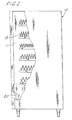
- the vending machine of the present invention is shown generally as 10 in Figs. 1 and 2 and includes a product storage area 11 with a plurality of conventional spiral vending trays 12 which can be seen through the glass front panel 14. Positioned below the glass is a snack dispensing chamber assembly 20 into which product is dropped through an opening in the bottom of the product storage area 11.
- the dispensing chamber assembly 20 includes a delivery door 22 on the front of the machine that allows a customer access to the dispensing chamber to remove a selection that has been deposited there from the spiral vending trays 12 in a well known manner.
- a customer interactive area 24 is provided with a selection key panel, coin deposit and coin return, all of conventional construction and use.
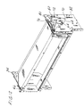
- Figs. 3-5 the dispensing chamber assembly 20 is shown removed from the vending machine 10 and with the delivery door 22 positioned in the closed position.
- Fig. 3 shows the right side of dispensing chamber assembly 20 with the linkage assembly 26 associated with the delivery door 22 to operate the anti-pilferage system as discussed below.
- Fig. 4 shows the left side of the dispensing chamber assembly 20 with the spring biasing assembly 28 discussed in detail below.
- the delivery door 22 is fixedly mounted to a support rod 30 which is pivotally mounted at its ends to the side members 32 and 34 of the dispensing chamber 20 to permit swinging movement of the delivery door 22.
- the delivery door 22 is constructed with a hard plastic outer piece 36 which is pushed by a customer to open the delivery door 22.
- the inner surface of the delivery door 22 is formed of a sheet metal piece 38 which is formed with a lower extended lip 40 that overlaps a mating sheet metal piece 42 mounted to the lower front of the vending machine housing so that as the delivery door 22 is partially opened the overlap prevents insertion of a wire or other pilferage device into the delivery chamber 20 before the rest of the anti-pilferage mechanism is fully in position.
- An anti-pilferage door 44 is similarly fixedly mounted to a rod 46 which is pivotally mounted at its ends in the side members 32 and 34.
- the anti-pilferage door 44 is made of sheet metal and in the closed position of the delivery door 22 rests against the inside of the delivery door so that the opening 47 from the product storage area into the dispensing chamber 20 is maximized.
- a rear door 48 is fixedly mounted to a rod 50 which is pivotally mounted at its ends to side members 32 and 34.
- the rear door 48 is of sheet metal construction.
- a rear panel 52 forms an upper rear portion of the dispensing chamber 20 and has an upper end which is folded to over hang the pivotal end of the rear door to prevent a wire or other pilferage device from being pushed past the rear door 48 and up into the product storage area 11.
- the linkage assembly 26 includes a delivery door lever arm 54 fixedly mounted at one end thereof to the end of rod 30 for pivotal movement with it and the delivery door 22.
- An opposite end of lever arm 54 is provided with a drive pin 56 which pivotally engages a first end of a drive link 58.
- the drive link 58 has a second end pivotally mounted through a drive pin 59 to a first leg 60 of a bell crank 62 which is pivotally mounted at a fixed center pivot point by pin 64 to side member 32.
- a second leg 66 of bell crank 62 has a drive link 68 pivotally mounted thereto at one end of the drive link 68 by pin 70.
- a second end of the drive link 68 is pivotally mounted by pin 72 to a first end of a rear door lever arm 74.
- An opposite end of the rear door lever arm 74 is mounted to the end of rear door mounting rod 50 for pivotal movement with the rod 50 and rear door 48.
- the first end of bell crank 62 has rotationally mounted by pin 76 to the back side thereof a cam follower 78 which engages dual camming surfaces 79 formed in anti-pilferage door lever arm 80.
- Anti-pilferage door lever arm 80 is mounted at one end to rod 46 for rotation therewith and with the anti-pilferage door 44 mounted thereto.
- the spring biasing assembly 28 includes a bell crank 82 mounted at a center pivot point by pin 84 to the side member 34.
- One end 86 of bell crank 82 is formed with a plurality of positioning holes 88 for receiving an end of a tensioning spring 90 therein.
- An opposite end of tensioning spring 90 is received in a single hole 92 formed in a bracket 94 fixed to the side member 34.
- Another end 96 of bell crank 82 is provided with dual camming surfaces 98 formed therein for receiving a cam follower 100.
- Cam follower 100 is rotationally mounted to one end of a drive link 102 which has an opposite end mounted to rod 46 for pivotal movement therewith and with anti-pilferage door 44.
- the overlap between the lip 40 formed on the inner sheet metal piece 38 of door 22 and corresponding piece 40 mounted to the front of the vending machine 10 prevent the insertion of a wire or similar pilferage device beneath the door 22.
- This overlap persists through the initial few degrees of pivoting of door 22, for example, 10-15 degrees.
- the anti-pilferage door 44 and rear door 48 are positioned out of the way of the opening of opening 47 between the product storage area 11 and the dispensing chamber 20 so that items from the storage area may freely fall from the storage area into the dispensing area for customer retrieval.
- the delivery door lever arm 54 and drive link 58 continue to pivot upwardly, as seen in Fig. 9, causing the bell crank 62 to pivot and follower 78 to move along camming surfaces 79 causing the anti-pilferage door 44 to come to rest against stops 104 on each side member 32 and 34.
- the rear side of lip 40 on the inside of the delivery door 22 engages the rear door 48 where it is connected to the rod 50 and thus acts as a stop for the open position of the delivery door 22.
- the rear door 48 lies against the inside of the delivery door 22 so there is no opening remaining to insert a wire or similar device. In this position the customer can remove the purchased item and release the door for closing.
- a spring biasing assembly 28 is provided to assist in reducing the necessary force to open the door 22 as well as providing a biasing force to close the door 22.
Landscapes
- Physics & Mathematics (AREA)
- General Physics & Mathematics (AREA)
- Control Of Vending Devices And Auxiliary Devices For Vending Devices (AREA)
Applications Claiming Priority (2)
| Application Number | Priority Date | Filing Date | Title |
|---|---|---|---|
| US09/169,637 US5909823A (en) | 1998-10-09 | 1998-10-09 | Anti-pilferage door system for a vending machine |
| US169637 | 1998-10-09 |
Publications (2)
| Publication Number | Publication Date |
|---|---|
| EP0992955A2 true EP0992955A2 (de) | 2000-04-12 |
| EP0992955A3 EP0992955A3 (de) | 2004-05-12 |
Family
ID=22616529
Family Applications (1)
| Application Number | Title | Priority Date | Filing Date |
|---|---|---|---|
| EP99307824A Withdrawn EP0992955A3 (de) | 1998-10-09 | 1999-10-05 | Diebstahlsicherungstürsystem für einen Verkaufsautomat |
Country Status (3)
| Country | Link |
|---|---|
| US (1) | US5909823A (de) |
| EP (1) | EP0992955A3 (de) |
| CA (1) | CA2285526A1 (de) |
Families Citing this family (11)
| Publication number | Priority date | Publication date | Assignee | Title |
|---|---|---|---|---|
| DE19946609B4 (de) * | 1999-09-29 | 2005-08-11 | Deutsche Wurlitzer Gmbh | Warenautomat mit mehreren übereinander angeordneten Warenfächern |
| JP2002223130A (ja) * | 2001-01-25 | 2002-08-09 | Fujitsu Ltd | 送信装置および送信方法 |
| US20040245280A1 (en) * | 2003-06-04 | 2004-12-09 | The Vendo Company | Anti-theft hopper for vending machine |
| US20050205596A1 (en) * | 2004-02-27 | 2005-09-22 | Maytag Corporation | Self-locking anti-pilfer gate for a vending machine |
| US7264138B2 (en) * | 2004-03-01 | 2007-09-04 | Dixie-Narco, Inc. | Anti-pilfering device for a vending machine |
| ITVR20040063A1 (it) * | 2004-04-20 | 2004-07-20 | Fas International Spa | Distributore automatico |
| EP2702505A1 (de) * | 2011-04-26 | 2014-03-05 | Crane Merchandising Systems, Inc. | Ada-kompatibilität in verkaufsautomaten |
| US9330519B2 (en) * | 2011-04-26 | 2016-05-03 | Jofemar, S.A. | Automatic dispensing machine |
| CN103903346B (zh) * | 2012-12-29 | 2016-12-14 | 重庆界威模具股份有限公司 | 自动售货机 |
| CN108734861A (zh) * | 2017-04-18 | 2018-11-02 | 深圳市祈飞科技有限公司 | 用于防盗和密封的取物口 |
| US11222499B2 (en) * | 2018-08-21 | 2022-01-11 | Automated Merchandising Systems, Inc. | Lifting body for a vending machine delivery bin |
Citations (1)
| Publication number | Priority date | Publication date | Assignee | Title |
|---|---|---|---|---|
| US5375737A (en) | 1993-09-29 | 1994-12-27 | Unidynamics Corporation | Vend door assembly |
Family Cites Families (8)
| Publication number | Priority date | Publication date | Assignee | Title |
|---|---|---|---|---|
| US3174646A (en) * | 1962-09-17 | 1965-03-23 | Vendo Co | Mechanism for vending articles from inclined support |
| US3344953A (en) * | 1965-02-18 | 1967-10-03 | Krakauer Merrill | Article vending machine having helical feeder coil |
| US3901366A (en) * | 1973-10-09 | 1975-08-26 | Umc Ind | Vendor particularly for cartons of cigarettes or like packages |
| US3940016A (en) * | 1974-07-25 | 1976-02-24 | Merrill Krakauer | Article vending apparatus with door interlock |
| US4094440A (en) * | 1976-09-23 | 1978-06-13 | Gross-Given Manufacturing Company | Safety door mechanism |
| US4196951A (en) * | 1978-03-20 | 1980-04-08 | Gross-Given Manufacturing Company | Vendor with door and shelf interlock |
| US4171752A (en) * | 1978-03-31 | 1979-10-23 | Gross-Given Manufacturing Company | Vending machine locking apparatus |
| US4296872A (en) * | 1979-09-21 | 1981-10-27 | Rowe International, Inc. | Delivery box assembly for merchandising machine |
-
1998
- 1998-10-09 US US09/169,637 patent/US5909823A/en not_active Expired - Fee Related
-
1999
- 1999-10-05 EP EP99307824A patent/EP0992955A3/de not_active Withdrawn
- 1999-10-07 CA CA002285526A patent/CA2285526A1/en not_active Abandoned
Patent Citations (1)
| Publication number | Priority date | Publication date | Assignee | Title |
|---|---|---|---|---|
| US5375737A (en) | 1993-09-29 | 1994-12-27 | Unidynamics Corporation | Vend door assembly |
Also Published As
| Publication number | Publication date |
|---|---|
| EP0992955A3 (de) | 2004-05-12 |
| US5909823A (en) | 1999-06-08 |
| CA2285526A1 (en) | 2000-04-09 |
Similar Documents
| Publication | Publication Date | Title |
|---|---|---|
| US5375737A (en) | Vend door assembly | |
| US8109410B2 (en) | Anti-pilfering device for a vending machine | |
| US5909823A (en) | Anti-pilferage door system for a vending machine | |
| US4296872A (en) | Delivery box assembly for merchandising machine | |
| CA1107695A (en) | Trap door for vending machine | |
| US3958821A (en) | Door operating assembly for merchandising machine or the like | |
| EP0139209B1 (de) | Münzbetätigte Ausgabevorrichtung zur Ausgabe von horizontal gestapelten Gegenständen, wie z.B. Zeitungen,von der oberen Seite des Stapels | |
| US4735344A (en) | Device in an automatic vending machine for holding objects dispensed by the latter | |
| US20050205596A1 (en) | Self-locking anti-pilfer gate for a vending machine | |
| US5064104A (en) | Apparatus for vending a product | |
| US4693357A (en) | Multiple chute coin mechanism | |
| EP1256913A2 (de) | Mit einer Diebstahlssicherungseinrichtung ausgerüsteter Verkaufsautomat für verpackte Produkte | |
| JP3478056B2 (ja) | 自動販売機の商品取出口 | |
| GB2178733A (en) | Countertop snack vendor | |
| EP0950995A2 (de) | Anordnung einer Kippschale als Kundenzugang zu einem Verkaufsautomat | |
| US4579215A (en) | Multiple chute coin mechanism | |
| US4570821A (en) | Article-dispensing assembly for a vending machine | |
| US11769363B1 (en) | Feminine hygiene product dispenser with trigger | |
| JP2541012Y2 (ja) | 自動販売機の商品投出口装置 | |
| US4257657A (en) | Readily releasable mechanism for locking a merchandising machine door in open position | |
| US5433340A (en) | Vending device | |
| JP2004245536A (ja) | 貯蔵庫 | |
| EP1431930A2 (de) | Geldaufbewahrungseinheit | |
| JP2001101496A (ja) | 自動販売機の商品取出口装置 | |
| JP2868055B2 (ja) | 直積み式商品払出装置 |
Legal Events
| Date | Code | Title | Description |
|---|---|---|---|
| PUAI | Public reference made under article 153(3) epc to a published international application that has entered the european phase |
Free format text: ORIGINAL CODE: 0009012 |
|
| AK | Designated contracting states |
Kind code of ref document: A2 Designated state(s): AT BE CH CY DE DK ES FI FR GB GR IE IT LI LU MC NL PT SE |
|
| AX | Request for extension of the european patent |
Free format text: AL;LT;LV;MK;RO;SI |
|
| RIN1 | Information on inventor provided before grant (corrected) |
Inventor name: WALTER, FRANK, L. Inventor name: REESE, ROBERT, J. Inventor name: RANFT, PHILIP M. |
|
| PUAL | Search report despatched |
Free format text: ORIGINAL CODE: 0009013 |
|
| AK | Designated contracting states |
Kind code of ref document: A3 Designated state(s): AT BE CH CY DE DK ES FI FR GB GR IE IT LI LU MC NL PT SE |
|
| AX | Request for extension of the european patent |
Extension state: AL LT LV MK RO SI |
|
| AKX | Designation fees paid | ||
| REG | Reference to a national code |
Ref country code: DE Ref legal event code: 8566 |
|
| STAA | Information on the status of an ep patent application or granted ep patent |
Free format text: STATUS: THE APPLICATION IS DEEMED TO BE WITHDRAWN |
|
| 18D | Application deemed to be withdrawn |
Effective date: 20041113 |
|
| REG | Reference to a national code |
Ref country code: HK Ref legal event code: WD Ref document number: 1029424 Country of ref document: HK |