EP0992629A2 - Vorrichtung zum mechanischen Abtragen von Wildkraut - Google Patents
Vorrichtung zum mechanischen Abtragen von Wildkraut Download PDFInfo
- Publication number
- EP0992629A2 EP0992629A2 EP99119492A EP99119492A EP0992629A2 EP 0992629 A2 EP0992629 A2 EP 0992629A2 EP 99119492 A EP99119492 A EP 99119492A EP 99119492 A EP99119492 A EP 99119492A EP 0992629 A2 EP0992629 A2 EP 0992629A2
- Authority
- EP
- European Patent Office
- Prior art keywords
- tool
- working
- shaft
- tool shaft
- axis
- Prior art date
- Legal status (The legal status is an assumption and is not a legal conclusion. Google has not performed a legal analysis and makes no representation as to the accuracy of the status listed.)
- Granted
Links
- 241000196324 Embryophyta Species 0.000 title claims description 25
- 239000004575 stone Substances 0.000 claims description 12
- 238000003754 machining Methods 0.000 claims description 10
- 230000005484 gravity Effects 0.000 claims description 8
- 238000009826 distribution Methods 0.000 claims description 6
- 238000000034 method Methods 0.000 claims 1
- 238000003825 pressing Methods 0.000 abstract description 6
- 230000001419 dependent effect Effects 0.000 abstract description 3
- 230000006835 compression Effects 0.000 description 8
- 238000007906 compression Methods 0.000 description 8
- 244000007853 Sarothamnus scoparius Species 0.000 description 7
- 238000004140 cleaning Methods 0.000 description 6
- 210000002414 leg Anatomy 0.000 description 6
- 239000002184 metal Substances 0.000 description 6
- 238000007788 roughening Methods 0.000 description 6
- 235000008216 herbs Nutrition 0.000 description 5
- 239000002689 soil Substances 0.000 description 4
- -1 clad Substances 0.000 description 3
- 230000000694 effects Effects 0.000 description 3
- 239000004033 plastic Substances 0.000 description 3
- 229910000831 Steel Inorganic materials 0.000 description 2
- 230000001680 brushing effect Effects 0.000 description 2
- 238000007688 edging Methods 0.000 description 2
- 235000015097 nutrients Nutrition 0.000 description 2
- 239000010959 steel Substances 0.000 description 2
- 239000000725 suspension Substances 0.000 description 2
- 238000010408 sweeping Methods 0.000 description 2
- 241000904500 Oxyspora paniculata Species 0.000 description 1
- 241001417527 Pempheridae Species 0.000 description 1
- 238000009825 accumulation Methods 0.000 description 1
- 239000000654 additive Substances 0.000 description 1
- 239000002969 artificial stone Substances 0.000 description 1
- 239000010426 asphalt Substances 0.000 description 1
- 230000015572 biosynthetic process Effects 0.000 description 1
- 238000005520 cutting process Methods 0.000 description 1
- 230000007423 decrease Effects 0.000 description 1
- 230000008030 elimination Effects 0.000 description 1
- 238000003379 elimination reaction Methods 0.000 description 1
- 230000002996 emotional effect Effects 0.000 description 1
- 230000002349 favourable effect Effects 0.000 description 1
- 210000003746 feather Anatomy 0.000 description 1
- 238000003197 gene knockdown Methods 0.000 description 1
- 230000001681 protective effect Effects 0.000 description 1
- 230000001105 regulatory effect Effects 0.000 description 1
- 239000004576 sand Substances 0.000 description 1
- 239000002893 slag Substances 0.000 description 1
- 239000007787 solid Substances 0.000 description 1
- 238000003971 tillage Methods 0.000 description 1
- 210000000689 upper leg Anatomy 0.000 description 1
- 238000009423 ventilation Methods 0.000 description 1
- 238000011179 visual inspection Methods 0.000 description 1
- XLYOFNOQVPJJNP-UHFFFAOYSA-N water Substances O XLYOFNOQVPJJNP-UHFFFAOYSA-N 0.000 description 1
Images


Classifications
-
- A—HUMAN NECESSITIES
- A01—AGRICULTURE; FORESTRY; ANIMAL HUSBANDRY; HUNTING; TRAPPING; FISHING
- A01M—CATCHING, TRAPPING OR SCARING OF ANIMALS; APPARATUS FOR THE DESTRUCTION OF NOXIOUS ANIMALS OR NOXIOUS PLANTS
- A01M21/00—Apparatus for the destruction of unwanted vegetation, e.g. weeds
- A01M21/02—Apparatus for mechanical destruction
-
- A—HUMAN NECESSITIES
- A46—BRUSHWARE
- A46B—BRUSHES
- A46B13/00—Brushes with driven brush bodies or carriers
- A46B13/02—Brushes with driven brush bodies or carriers power-driven carriers
-
- E—FIXED CONSTRUCTIONS
- E01—CONSTRUCTION OF ROADS, RAILWAYS, OR BRIDGES
- E01H—STREET CLEANING; CLEANING OF PERMANENT WAYS; CLEANING BEACHES; DISPERSING OR PREVENTING FOG IN GENERAL CLEANING STREET OR RAILWAY FURNITURE OR TUNNEL WALLS
- E01H1/00—Removing undesirable matter from roads or like surfaces, with or without moistening of the surface
- E01H1/02—Brushing apparatus, e.g. with auxiliary instruments for mechanically loosening dirt
- E01H1/05—Brushing apparatus, e.g. with auxiliary instruments for mechanically loosening dirt with driven brushes
- E01H1/053—Brushing apparatus, e.g. with auxiliary instruments for mechanically loosening dirt with driven brushes having vertical axes
-
- E—FIXED CONSTRUCTIONS
- E01—CONSTRUCTION OF ROADS, RAILWAYS, OR BRIDGES
- E01H—STREET CLEANING; CLEANING OF PERMANENT WAYS; CLEANING BEACHES; DISPERSING OR PREVENTING FOG IN GENERAL CLEANING STREET OR RAILWAY FURNITURE OR TUNNEL WALLS
- E01H11/00—Control of undesirable vegetation on roads or similar surfaces or permanent ways of railways, e.g. devices for scorching weeds or for applying herbicides; Applying liquids, e.g. water, weed-killer bitumen, to permanent ways
Definitions
- the invention relates to a device for mechanically removing weeds from paved ground surfaces, such as paths, streets, squares or channels, with at least one working tool rotating on the ground surface about an approximately vertical tool shaft.
- paved surfaces is understood to mean, among other things, paved, asphalted, concrete, clad, water-bound or the like paved surface types (with or without a curb or similar edging), which are used, for example, as a footpath, bicycle path and / or car road or as Decorative area or parking space are provided.
- Wild herb refers to the entirety of plants which are conventionally called weeds. It is within the scope of the invention to remove the nutrient medium of the wild herb accumulated on the paved surface with the aid of the device. The device should therefore be suitable for sweeping.
- weeds succeed, from the surface edges, e.g. from the gutter, from or out of joints spread over the area. This is particularly evident on foot and bicycle paths, which are kept clean by traffic on a median, but supported from the edges by accumulation of nutrient media gradually grow.
- DE 195 02 010 A1 describes a device for removing weed growth on roads and described because of.
- This movable device has at least one cross component moved back and forth with brushing elements directed towards the floor, which has to be pressed against the ground during operation.
- the single ones The height of the brush elements can be shifted relative to the floor. They can also be hung with a pendulum.
- the attachment the individual brush elements are constantly adapted to the shape of the floor.
- the pressing force of the elements must also be permanently regulated according to visual inspection - be adapted to the work objective and result.
- This device includes a brushing device with a plate broom.
- the plate broom is motorized in Rotation offset and aligned so that it brushes off the weed surfaces. He has a large number of tufts (cleaning bristles) in certain angular positions are lockable with respect to the axis of rotation of the broom.
- the angular position is carried out according to the respective task using a spindle or fixed a hydraulic cylinder or other adjustment device.
- the pressure with which the plate broom has to move against the surface to be cleaned must be - completely Similar to the aforementioned devices - with the help of additional mechanical or hydraulic devices can be applied.
- roller brooms if their Work is supposed to be successful with relatively great strength, for example using a hydraulic or mechanical system, pressed against the floor surface to be cleaned become.
- pressing has the disadvantage that the tools have to be cleaned Roughen the floor surface made of artificial stones, slabs, asphalt or concrete. The leads to later moss formation after rainfall and thus to smoothness and Slipping.
- the soft or fine parts of the patch are scraped out, so that finally a noticeably uneven paved surface with the aforementioned disadvantages arises.
- DE-PS 327 329 a rotating brush with interchangeable metal tines described, in which the tines are suspended radially to the brush axis.
- the tines are attached in such a way that they also play radially Have to step forward or backward if there is too much resistance on the brushed surface.
- the tines should not be radial, but be arranged so that the suspended on the circumference of the brush body Tines around their suspension point from the axial direction to the radial one Are pivotable towards.
- a separate pressing means e.g. also by hand, against the one to be treated Workpiece to be pressed.
- the invention has for its object a mechanical cleaning device to create that practically does not cause roughening of the paved surface, but ensures that the undesired wild herbs are cut down to the roots.
- the cleaning effect should preferably extend into the edges or Grooves of a gutter can extend into it.
- the invention preferably consists in the fact that the working tool is used the centrifugal force is positioned relative to the ground surface.
- the work tool is stored on a support that is approximately vertical, downward tool shaft is rotatable.
- Working tool in relation to the tool shaft or in relation to the carrier an approximately horizontal tilt axis can be pivoted. The swivel angle of the working tool around the tilt axis and thus the position relative to the opposite machining area, is then dependent on a centrifugal force, which in turn depends on the speed of rotation of the tool shaft.
- the centrifugal force is used in the context of the invention.
- the respective work tool for example, with a type of centrifugal governor mechanically coupled.
- a centrifugal governor rotating on the axis of the tool shaft be provided, which is constructed and connected to the tool that the working side of the tool - if necessary knocking off the weeds increasing number of revolutions of the tool shaft has an intense effect.
- centrifugal force does not lower, but instead is used rather for easy ventilation of the tool, so that the latter is tangential, e.g. practically without touching the floor, to a certain extent stroking the floor surface glides and, without roughening them, cuts off the wild herbs at the root resp.
- the work noises are remarkably low because of the work tools practically do not touch the floor surface and essentially only the Engine hears.
- at least two are each pivotable on an approximately horizontal tilt axis stored working tools, e.g. trained like stick brushes, provided as well overall be balanced so that each tool forming a double lever through its tilt axis in a bristle arm or leg on the one hand and divided into a preferably lighter weight arm or leg on the other hand is.
- the work tool with the weight distribution mentioned can be pivoted about a horizontal tilt axis.
- the work tool can then be an external one Resistance, e.g. giving way to an obstacle like a gutter edge dodge; this protects the tool and its bristles and the respective obstacle is not scratched unnecessarily.
- the tool can be moved radially on the tilt axis with a Guide part facing away from the working side can be moved longitudinally at the rear end be accommodated in a sleeve.
- the restoring force should then, preferably as Compression spring, act on the rear end.
- the compression spring (or the like Restoring force) are trained and stored so that they have two tasks fulfilled: on the one hand, it should exert a force in the longitudinal direction of the tool or sleeve, which a dodging (yielding) of the tool in the event of harmful knocking - harmful to tools and / or obstacles - to an obstacle.
- the compression spring used as the restoring means should be designed and stored in such a way that on the tool - at its rear end - a force tangential in Can exercise in relation to the tilt axis. This tangential force should be balanced be that the working side of the tool with the machine at rest and starting is clearly lifted off the ground.
- the bristle end of the cleaning tool according to the invention can be in one preferred embodiment of a multi-core wire rope piece or end consist.
- the piece of wire rope should be selected so that it is used the first time the device at the free end fanned out like a brush and thereby becomes functional with regard to the cleaning task.
- the wire rope piece instead of the wire rope piece also uses a plastic rope piece or other brush become.
- the respective brush part is generally a wearing part, it can therefore be replaced separately.
- the wire rope piece with the help of at least one during operation of the Tool as well as its parts wearing sheet metal ring.
- two such rings have been sufficient.
- the rings use at the same time with the working side of the tool, but at the same time they prevent that Tool farther - seen in the longitudinal direction of the tool - is fanned out than for normal operation required.
- a support that is optionally provided according to the invention is attached to the tool shaft preferably attached symmetrically with respect to the shaft or its axis.
- the carrier is also preferably driven directly by or via the at Operation rotating tool shaft.
- the carrier alone or preferably together with the respective work tool to balance.
- the carrier provided according to the invention can in principle be like that Knives of a lawnmower are trained. At the long ends of this beam are (instead of the knives) not cutting in the case of the invention but Mounts, e.g. Tilt or swivel bearings, for at least one work tool each intended. In principle, a beam with two diametrically opposed Poor enough. It is also within the scope of the invention to have a carrier with three or more - preferably symmetrically distributed - to provide arms. In principle can the carrier can also be designed like a circular disc. A symmetrical structure the carrier with the parts attached to it is advantageous if a quiet Concentricity of the tool shaft is to be achieved.
- the carrier is preferably rotatable approximately horizontally overall stored such that the single rotating work tool the floor surface during the entire carrier revolution - approximately tangentially, that is in one direction along the bottom surface - processed.
- the chopped wild herb is possibly thrown along the floor surface, it can then be separated, e.g. with a sweeper.
- the carrier is inclined overall on the (vertical) Tool shaft mounted so that the single moving tool the Floor area only on part of the circulation, preferably on less than that half round, processed.
- the single work tool will still be moved around in a circle approximately parallel to the floor surface, but edited it the floor area only on part of the circle. If necessary, the dismissed Weeds by moving the slanted support from the ground lifted off, and it can then be placed in a correspondingly inclined collecting duct - Through which the carrier rotates with the respective working tool - collected and fed directly to a collection container.
- the carrier should preferably not wobble, but rather the inclination should be essentially solid spatially.
- This has the advantage that the work tools always in a spatially fixed angular range with respect to the device or swipe their operator along the floor surface and that the cut weeds are always in the same area around the Carrier lifted from the floor surface and fed to a collecting channel can.
- a carrier is driven directly by the tool shaft should be, it is useful in a kind of shoulder bearing from the tool shaft added.
- Such a shoulder bearing enables a spatially fixed Oblique position of the support, which may rotate with the shaft.
- the carrier can be coupled to the shaft via a driver.
- the tool shaft becomes a certain circumferential element of the rotating one Carrier on one - like the carrier - obliquely with respect to the axis of the tool shaft standing circle.
- the slant of the beam in relation to the Tool shaft) can be stabilized in that the work tool in one spatially fixed circumferential area (of the carrier) sweeps along an impact surface, which is part of the collection channel.
- the device according to the invention is preferably used during operation rotating carrier with working tools on top and bell-shaped in principle covering housing.
- the housing can also be a chassis of the Enclose device.
- the housing protects against that from the floor or from rotating tool, even detached parts can be thrown into the environment.
- the housing can also be used with a collecting duct etc. for the chipped Weeds are equipped.
- the chassis is - e.g. for simplified steering - preferably with three or four Equipped with rollers or wheels.
- One of the rollers can be in the middle in the transport direction be positioned in front of the swivel circle of the work tools while a pair of rollers should be behind the swivel circle in the direction of transport.
- the Pair of rollers can be symmetrical or asymmetrical with respect to those by the axis alignment line of the intended feed direction of the tool shaft Be positioned device.
- the wheelbase of the chassis or the position of the individual wheels of the chassis should be chosen so that the machining area covered by the work tools - Especially with a rotatable overall in a horizontal plane Carrier - at least on one side of the device or on one side over the wheels (Wheel track) survives. This ensures that the machining circle is close a device approaching a gutter right into the edge between the floor surface and gutter reach and the bristles engage in this edge and there Can remove weeds.
- the housing covering the work tools and rollers can, at least on the side facing the floor, be essentially rectangular to square, but can also be designed in any other shape.
- at least one side part of the housing is designed as a housing flap which can be pivoted, preferably about a horizontal folding axis upwards, in particular against gravity or against spring force, and which also protects against stone chipping in its position pivoted away from the bell shape.
- Stone chips are understood to mean parts, in particular stones, which are thrown to the side by actuating the working tools according to the invention - away from the device according to the invention.
- the housing flap according to the invention can, for example, to the side or to the side be formed foldable above.
- the distance of the respective Folding axis or the like from the tool shaft smaller than the working radius of the work tools. This ensures that after pivoting away Housing flap the work tools no longer prevented by the housing are to engage in a gutter edge or the like throat. The elimination this possible disability is only part of this invention Aspect. In addition, there is the protection against stone chipping that is also obtained.
- the housing flap is not somehow swung away, but in such a way that stones that may have been thrown away by the working tools the working area in a gutter-throat position catches.
- the housing flap is preferably on a horizontal Folding axis stored and if necessary raised up and on the Top edge of the obstacle, e.g. of the gutter of a sidewalk edge. Then when a stone is thrown in the direction of the raised hatch he flies either against the gutter or against the one above Housing flap; the stone cannot endanger the environment.
- the (downward) longitudinal edges of the housing flap can - seen in Direction of transport - be designed like a skid so that the housing flap itself automatically raises to the respective upper level when driving against a curb.
- the housing flap is preferred to move by itself, e.g. by the spring force and / or gravity, down to the normal position pivoted.
- the housing flap When the housing flap is lifted, it may be free at its longitudinal ends openings can be thrown out, even if at these points should be excluded from objects by hanging rags, especially rubber rags with stiffening weight, e.g. embedded metal rail, getting closed. Also on the other bottom edges of the case, those facing the respective floor area can reach down to the floor Protective means against ejecting objects are provided.
- Single or double brush strips, the bristles of which have proven effective Are directed towards the bottom, preferably the free bristle ends should light the bottom touch.
- the brush strips can be used for even better protection against stone chips combined with elastic bands that extend along the strips or be replaced by such tapes.
- two or more according to the invention can also be used Devices side by side or offset to a tractor or the like like a large lawn mower.
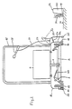
- the tillage machine for weed removal according to FIGS. 1 and 2 comprises a carrier 2 fastened on a tool shaft 1 which is rotatable during operation with attached work tools 3.
- the carrier 2 should be non-rotatable and fixed in a horizontal plane overall on the tool shaft 1 become.
- the tool shaft 1 can be the output shaft of a motor 4.
- the carrier becomes approximately vertical downward tool shaft 1 symmetrical with respect to its axis 5 attached. It has at least two on its periphery 6 on approximately horizontal Axes, the tilt axes 7, stored tools 3 and is overall in relation balanced on axis 5.
- Each tool 3 according to FIGS. 1 and 2 is characterized by its Tilt axis 7 divided into a bristle arm 8 and a weight arm 9. On the latter can attack any restoring means - so-called bristle lifters 47 - which lift the bristle arm 8 off the ground when the shaft 1 is at rest.
- a restoring device come, for example, elastic tension springs or (from above on the Low weight pressing) leaf springs in question; the leaf springs can e.g. from steel exist or be designed as a rubber profile.
- the carrier 2 preferably consists of a single propeller-like double arm, its longitudinal ends - diametrically opposite with respect to the tool shaft 1 - carry one of the tools 3 each.
- the double arm is shown in FIGS. 1 and 2 his tool 3 acting on the respective floor surface 10 with a housing 11 (above and all around) covered, which also includes a chassis, e.g. with three or four wheels or rollers 12 - 14, covered.
- a bracket 15 can be attached to the housing 11 be attached, which allows the device in the respective feed direction 18 to lead.
- the machining circle 17 covered by the tools 3 can at least be on a cut longitudinal side 11a of the housing 11 over the one located there Extend roll 14 or the associated wheel track. This makes it possible for the bristle tips 18 of the bristle arm 8 into the edge 19 on the edge of a gutter Intervene 20 and knock down the weeds 21 located there to the root. If the housing 11 interferes with this work, it can on one side the machining circle 17 protrudes laterally over a wheel 14, for example with a pivotable about an approximately horizontal folding axis 22 (also as a fender designated) housing flap 23 are equipped. The housing flap 23 If necessary, this overlaps the cut-out longitudinal side 11a of the housing 11.
- the housing 11 In the position on the gutter top 26, the housing 11 is open in the direction on gutter 20. However, this protects there (together with the raised Housing flap 23) the environment in front of thrown objects. Otherwise Perimeter of the lower edge of the housing 11 can protect the environment Brush strips 29 and rubber strips 49 are attached.
- the bristle part 30 of the bristle arm 8 is generally designed as a wearing part. This can be done, for example, in a sleeve 31 of the bristle arm 8 a clamping screw 32 or be locked by hooking.
- the tool 3 alternatively, in order to minimize brush wear, as explained above, axially, that is, in its longitudinal direction, freely movable - e.g. by about 15 to 20 mm - stored and tied off once or twice using a sheet metal ring. details 5 are drawn in principle in the cutout of FIG.
- the Tool 3 has a working end 51, a guide part 52 and a rear end 53. The working end 51 slides with its flattened after a short period of operation Working surface 54 over the floor surface to be processed 10.
- the guide part 52 is movably received in a sleeve 56 in the longitudinal direction 55 of the tool 3.
- the clamping screw 32 of Fig. 1 is then omitted.
- the sleeve 56 in turn is pivotally held on the tilt axis 7.
- Compression spring 57 which on a stand 58, e.g. can be attached to the carrier 2, is stored.
- the compression spring 57 should be designed so that it forces in the longitudinal direction 55 and in the tangential direction 59 (i.e. in the circumferential direction of the Axis 7) can catch elastically.
- the embodiment also shows two sheet metal rings 60 on the working end 51 of the tool 3.
- Fig. 3 shows an embodiment in which as a pressing means of the work tool 3 a centrifugal governor 33 rotating about the axis 5 of the tool shaft 1 is provided.
- the work tool 3 is on an approximately horizontal Tilt axis 7 mounted on the carrier 2.
- the latter is preferably non-rotatable connected to the tool shaft 1.
- a tool shaft 1 is shown in FIG Regulator disc 34 mounted, and movable in the manner shown with a Bristle arm 8 with respect to the adjustment leg 35 opposite the tilt axis 7 which corresponds to the aforementioned weight arm 9 - connected.
- a holding disc 36 firmly (non-rotatably) connected.
- a compression coil spring 37 is tensioned in this way arranged that the regulator disk 34 normally (without any other load) in the direction of gravity 38, that is pressed in the direction of the carrier 2 becomes. In many cases, gravity alone is sufficient to control the regulator disk 34 normally move towards the carrier 2; then the helical spring 37 fall away.
- weights 40 arranged or clamped. The weights 40 can be seen when the tool shaft 1 rotates Direction of centrifugal force 41 driven radially outward (with respect to shaft 1). As a result, the regulator disk 34 moves upward against the direction of gravity 38 or moved to the holding disc 36. This in turn has the consequence that the adjusting leg 35 of the work tool 3 raised and the bristle arm 8 in the direction Floor area 10 is lowered. The extent of the lowering movement can be determined by a Stop 48 can be limited.
- the carrier 2 are fixed in the embodiments of FIGS. 1 to 3 with the Tool shaft 1 connected so that the individual carrier in total approximately in one horizontal plane is rotated when the shaft 1 rotates.
- the carrier 2 is rotated as a whole with respect to the Tool shaft 1 set so that the individual traveling tool 3 the Floor area 10 only processed on a part of the associated circuit.
- a 4 is that the tool holder 2 in one so-called shoulder bearing 42 is mounted on the shaft 1. Through the shoulder camp 42 and a driver 43 connected to the shaft 1 ensures that the when the shaft 1 rotates, the rotating carrier 2 does not wobble, but rather the one in FIG. 4 shown oblique position - seen spatially - essentially constant.
- the work tool 3 chopped wild herbs 21 lifted off the bottom surface 10 and over a baffle 44 provided in the housing 11, a collecting duct 45 and are fed there from a collecting container 46.
Landscapes
- Engineering & Computer Science (AREA)
- Architecture (AREA)
- Structural Engineering (AREA)
- Life Sciences & Earth Sciences (AREA)
- Civil Engineering (AREA)
- Pest Control & Pesticides (AREA)
- Zoology (AREA)
- Environmental Sciences (AREA)
- Wood Science & Technology (AREA)
- Insects & Arthropods (AREA)
- Mechanical Engineering (AREA)
- Soil Working Implements (AREA)
- Catching Or Destruction (AREA)
- Harvester Elements (AREA)
- Centrifugal Separators (AREA)
- Agricultural Chemicals And Associated Chemicals (AREA)
Abstract
Description
- Fig. 1
- einen vertikalen Schnitt parallel zur Vorschubrichtung einer erfindungsgemäßen Vorrichtung mit durch Fliehkraft gesteuerten Arbeitswerkzeugen;
- Fig. 2
- die Vorrichtung nach Fig. 1 im vertikalen Schnitt senkrecht zur Vorschubrichtung;
- Fig. 3
- ein Arbeitswerkzeug mit Steuerung durch einen Fliehkraftregler;
- Fig. 4
- eine erfindungsgemäße Vorrichtung mit insgesamt schräg gestellt auf der Werkzeugwelle rotierendem Träger des jeweiligen Arbeitswerkzeugs; und
- Fig. 5
- Teilzeichnung der Werkzeugaufhängung.
- 1
- = Werkzeugwelle
- 2
- = Träger
- 3
- = Arbeitswerkzeug
- 4
- = Motor
- 5
- = Achse (1)
- 6
- = Peripherie (2)
- 7
- = Kippachse
- 8
- = Borstenarm
- 9
- = Gewichtsarm
- 10
- = Bodenfläche
- 11
- = Gehäuse
- 12-14
- = Rollen
- 15
- = Haltebügel
- 16
- = Vorschubrichtung
- 17
- = Bearbeitungskreis
- 18
- = Borstenspitze
- 19
- = Rinnsteinkante
- 20
- = Rinnstein
- 21
- = Wildkraut
- 22
- = Klappachse
- 23
- = Gehäuseklappe
- 24
- = Feder
- 25
- = Kunststoffkufe
- 26
- = Oberseite (20)
- 27
- = Zugseil
- 28
- = Schalthebel
- 29
- = Bürstenleiste
- 30
- = Borstenteil (8)
- 31
- = Hülse
- 32
- = Klemmschraube
- 33
- = Fliehkraftregler
- 34
- = Reglerscheibe
- 35
- = Stellschenkel
- 36
- = Haltescheibe
- 37
- = Druckfeder
- 38
- = Schwerkraftrichtung
- 39
- = Schenkel
- 40
- = Gewicht
- 41
- = Fliehkraftrichtung
- 42
- = Schulterlager
- 43
- = Mitnehmer
- 44
- = Prallfläche
- 45
- = Sammelkanal
- 46
- = Sammelbehälter
- 47
- = Borstenarmheber (Fig. 2)
- 48
- = Anschlag
- 49
- = Gummistreifen
- 51
- = Arbeitsende (3)
- 52
- = Führungsteil
- 53
- = Hinterende (3)
- 54
- = Arbeitsfläche (51)
- 55
- = Längsrichtung
- 56
- = Hülse
- 57
- = Druckfeder
- 58
- = Ständer
- 59
- = Transportrichtung
- 60
- = Blechring
Claims (13)
- Vorrichtung zum mechanischen Abtragen von Wildkraut (21) von befestigten Bodenflächen (10), wie Wegen, Straßen, Plätzen oder Rinnen, mit mindestens einem um eine etwa vertikale Werkzeugwelle (1) rotierend auf die Bodenfläche (10) einwirkenden Arbeitswerkzeug (3), dadurch gekennzeichnet, daß das Arbeitswerkzeug (3) durch Ausnutzung der Fliehkraft relativ zur Bodenfläche (10) positioniert ist.
- Vorrichtung nach Anspruch 1, dadurch gekennzeichnet, daß das Arbeitswerkzeug (3) auf einer etwa horizontalen Kippachse (7) schwenkbar an der Werkzeugwelle (1) gelagert ist.
- Vorrichtung nach Anspruch 1 oder 2, dadurch gekennzeichnet, daß das einzelne Arbeitswerkzeug (3) so auf dem Träger (2) gelagert ist, daß es infolge der Fliehkraft über die Bodenfläche (10) gleitet (Fig. 1 und 2).
- Vorrichtung nach Anspruch 1 oder 2, dadurch gekennzeichnet, daß als Positioniermittel des Arbeitswerkzeugs (3) ein um die Achse (5) der Werkzeugwelle (1) rotierender Fliehkraftregler (33) vorgesehen ist (Fig. 3).
- Vorrichtung nach mindestens einem der Ansprüche 1 bis 3 dadurch gekennzeichnet, daß an der Peripherie (6) des Trägers (2) mindestens zwei auf etwa horizontalen Kippachsen (7) schwenkbar gelagerte Arbeitswerkzeuge (3) insgesamt zusammen mit dem Träger - in Bezug auf die Welle (1) - gewuchtet gelagert sind, daß jedes Arbeitswerkzeug (3) durch seine Kippachse (7) in einen Bürstenarm (8) und einen Gewichtsarm (9), der vorzugsweise leichter als der Bürstenarm (8) ist, unterteilt ist.
- Vorrichtung nach mindestens einem der Ansprüche 1 bis 5, dadurch gekennzeichnet, daß das Arbeitswerkzeug (3) mit einem, vorzugsweise abgebundenem (60), Drahtseilstück (51) als Borstenteil ausgebildet ist.
- Vorrichtung nach mindestens einem der Ansprüche 1 bis 6, dadurch gekennzeichnet, daß das Arbeitswerkzeug (3) auf einem mit der Werkzeugwelle (1) mitrotierendem Träger (2) befestigt ist und daß der Träger (2) beim Rotieren insgesamt schräg auf der Werkzeugwelle (1) gestellt ist, so daß das einzelne mitlaufende Arbeitswerkzeug (3) die Bodenfläche (10) nur auf einem Teil - vorzugsweise auf weniger als dem halben Umlauf - bearbeitet (Fig. 4).
- Vorrichtung zum mechanischen Abtragen von Wildkraut (21) von befestigten Bodenflächen (10), wie Wegen, Straßen, Plätzen oder Rinnen, mit mindestens einem um eine etwa vertikale Werkzeugwelle (1) rotierend auf die Bodenfläche (10) einwirkenden Arbeitswerkzeug (3), insbesondere nach mindestens einem der Ansprüche 1 bis 7, dadurch gekennzeichnet, daß der Bearbeitungskreis (17) der bei Betrieb rotierenden Arbeitswerkzeuge (3) - gegebenenfalls einschließlich Fahrwerk (12-14) - oben und rundum mit Hilfe eines im Prinzip glockenförmigen Gehäuses (11) überdeckt ist und daß wenigstens ein Seitenteil des Gehäuses (11) als schwenkbare Gehäuseklappe (23) ausgebildet ist, die auch in ihrer weggeschwenkten Position gegen Steinschlag schützt.
- Vorrichtung nach Anspruch 8, gekennzeichnet durch ein Fahrwerk (13, 14) dessen Radstand einseitig enger als der Durchmesser des durch das jeweilige Arbeitswerkzeug (3) bestrichenen Bearbeitungskreises (17) ist bzw. asymmetrisch in Bezug auf den Bearbeitungskreis (17) liegt.
- Vorrichtung nach Anspruch 8 oder 9, dadurch gekennzeichnet, daß die Gehäuseklappe (23) um eine etwa horizontale Klappachse (22) nach oben, insbesondere gegen die Schwerkraft oder gegen die Kraft einer Feder (24), schwenkbar ist, wobei der Abstand der Klappachse (22) von der Werkzeugwelle (1) kleiner als der Radius des Bearbeitungskreises (17) der Arbeitswerkzeuge (3) ist.
- Vorrichtung nach mindestens einem der Ansprüche 8 bis 10, dadurch gekennzeichnet, daß das Gehäuse (11) an seinen der Bodenfläche (10) zugewandten unteren Kanten mit einfachen oder doppelten, insbesondere mit Gummileisten (49) kombinierten Bürstenleisten (29), deren Borsten bzw. Kanten auf den Boden (10) gerichtet sind, ausgestattet ist.
- Vorrichtung nach mindestens einem der Ansprüche 1 bis 11, dadurch gekennzeichnet, daß das einzelne Arbeitswerkzeug (3) eine solche Lagerung bzw. Gewichtsverteilung besitzt, daß das Borstenteil (30) bei Rotieren der Werkzeugwelle (1) praktisch ohne Druck über die Bodenfläche (10) gleitet, aber bei Ruhen der Werkzeugwelle (1) durch eine Zusatzkraft (47) von der Bodenfläche (10) abgehoben ist.
- Vorrichtung nach mindestens einem der Ansprüche 1 bis 12, dadurch gekennzeichnet, daß das Arbeitswerkzeug (3) in seiner Längsrichtung (55) frei beweglich in einer Führung (56) auf der Kippachse gelagert ist und daß auf sein dem Arbeitsende (51) gegenüberliegendes Hinterende (53) eine insbesondere auch in der Umfangsrichtung (59) der Achse (7) wirksame Rückstellkraft (57) gerichtet ist.
Priority Applications (1)
| Application Number | Priority Date | Filing Date | Title |
|---|---|---|---|
| DK99119492T DK0992629T3 (da) | 1998-10-09 | 1999-09-30 | Apparat til mekanisk fjernelse af vildkrudt |
Applications Claiming Priority (6)
| Application Number | Priority Date | Filing Date | Title |
|---|---|---|---|
| DE29818113U | 1998-10-09 | ||
| DE29818113U DE29818113U1 (de) | 1998-10-09 | 1998-10-09 | Einrichtung zum mechanischen Entfernen von Wildkraut auf befestigten Bodenflächen mittels Schneidbesen |
| DE19849053 | 1998-10-24 | ||
| DE19849053 | 1998-10-24 | ||
| DE19855986 | 1998-12-04 | ||
| DE19855986 | 1998-12-04 |
Publications (3)
| Publication Number | Publication Date |
|---|---|
| EP0992629A2 true EP0992629A2 (de) | 2000-04-12 |
| EP0992629A3 EP0992629A3 (de) | 2001-11-07 |
| EP0992629B1 EP0992629B1 (de) | 2004-12-01 |
Family
ID=27218764
Family Applications (1)
| Application Number | Title | Priority Date | Filing Date |
|---|---|---|---|
| EP99119492A Expired - Lifetime EP0992629B1 (de) | 1998-10-09 | 1999-09-30 | Vorrichtung zum mechanischen Abtragen von Wildkraut |
Country Status (5)
| Country | Link |
|---|---|
| EP (1) | EP0992629B1 (de) |
| AT (1) | ATE283943T1 (de) |
| DE (2) | DE59911180D1 (de) |
| DK (1) | DK0992629T3 (de) |
| ES (1) | ES2234192T3 (de) |
Cited By (2)
| Publication number | Priority date | Publication date | Assignee | Title |
|---|---|---|---|---|
| CN110258407A (zh) * | 2019-07-26 | 2019-09-20 | 浙江工业职业技术学院 | 一种清扫刷连接装置及清扫设备 |
| CN110374038A (zh) * | 2019-07-20 | 2019-10-25 | 安徽省潜山县志发机电配件有限公司 | 一种可避免产生清扫死角的环卫刷 |
Families Citing this family (2)
| Publication number | Priority date | Publication date | Assignee | Title |
|---|---|---|---|---|
| DE20216915U1 (de) * | 2002-11-02 | 2003-01-16 | Reiners Christa | Langgestreckter Besen zum mechanischen Abtragen von Wildkraut von befestigten Bodenflächen |
| DE102010017608A1 (de) | 2010-06-25 | 2011-12-29 | Fiedler Maschinenbau Und Technikvertrieb Gmbh | Geräteträger und Ausleger für Reinigungsgeräte und Verfahren zur Steuerung eines Geräteträgers |
Citations (4)
| Publication number | Priority date | Publication date | Assignee | Title |
|---|---|---|---|---|
| DE327329C (de) | 1919-05-29 | 1920-10-09 | Wilh Kober & Co | Umlaufende Buerste mit auswechselbaren Metallzinken |
| DE3818645A1 (de) | 1988-06-01 | 1989-12-14 | Voss Hans Juergen | Bearbeitungsmaschine zur unkrautbeseitigung |
| DE19502010A1 (de) | 1994-01-25 | 1995-08-31 | Guenther Weiss | Verfahren und Gerät zum Entfernen von Wildkrautbewuchs |
| EP0692577A1 (de) | 1994-07-16 | 1996-01-17 | MOHR, Hermann | Kehrbürste (Wildkrautbürste) zum Abkehren von befestigten Flächen |
Family Cites Families (2)
| Publication number | Priority date | Publication date | Assignee | Title |
|---|---|---|---|---|
| US3045267A (en) * | 1961-02-07 | 1962-07-24 | Wagner Richard Valentin | Self-adjustable rotatable surface conditioning device |
| SE506677C2 (sv) * | 1990-12-10 | 1998-01-26 | Owe Westin | Sopmaskin |
-
1999
- 1999-09-30 DE DE59911180T patent/DE59911180D1/de not_active Expired - Lifetime
- 1999-09-30 EP EP99119492A patent/EP0992629B1/de not_active Expired - Lifetime
- 1999-09-30 AT AT99119492T patent/ATE283943T1/de active
- 1999-09-30 DK DK99119492T patent/DK0992629T3/da active
- 1999-09-30 DE DE19946892A patent/DE19946892A1/de not_active Withdrawn
- 1999-09-30 ES ES99119492T patent/ES2234192T3/es not_active Expired - Lifetime
Patent Citations (4)
| Publication number | Priority date | Publication date | Assignee | Title |
|---|---|---|---|---|
| DE327329C (de) | 1919-05-29 | 1920-10-09 | Wilh Kober & Co | Umlaufende Buerste mit auswechselbaren Metallzinken |
| DE3818645A1 (de) | 1988-06-01 | 1989-12-14 | Voss Hans Juergen | Bearbeitungsmaschine zur unkrautbeseitigung |
| DE19502010A1 (de) | 1994-01-25 | 1995-08-31 | Guenther Weiss | Verfahren und Gerät zum Entfernen von Wildkrautbewuchs |
| EP0692577A1 (de) | 1994-07-16 | 1996-01-17 | MOHR, Hermann | Kehrbürste (Wildkrautbürste) zum Abkehren von befestigten Flächen |
Cited By (2)
| Publication number | Priority date | Publication date | Assignee | Title |
|---|---|---|---|---|
| CN110374038A (zh) * | 2019-07-20 | 2019-10-25 | 安徽省潜山县志发机电配件有限公司 | 一种可避免产生清扫死角的环卫刷 |
| CN110258407A (zh) * | 2019-07-26 | 2019-09-20 | 浙江工业职业技术学院 | 一种清扫刷连接装置及清扫设备 |
Also Published As
| Publication number | Publication date |
|---|---|
| DE59911180D1 (de) | 2005-01-05 |
| EP0992629B1 (de) | 2004-12-01 |
| ES2234192T3 (es) | 2005-06-16 |
| ATE283943T1 (de) | 2004-12-15 |
| DK0992629T3 (da) | 2005-04-11 |
| EP0992629A3 (de) | 2001-11-07 |
| DE19946892A1 (de) | 2000-04-27 |
Similar Documents
| Publication | Publication Date | Title |
|---|---|---|
| EP2078113B1 (de) | Kombinationsgerät zum schneefräsen, mähen, vertikutieren, bodenhacken oder dgl. | |
| CH648369A5 (de) | Spur- oder planiergeraet fuer ski-loipen bzw. ski-pisten. | |
| DE1296866B (de) | Rasenpflegegeraet | |
| DE60029765T9 (de) | Verbesserung eines selbstgesteuerten rasenmähers | |
| DE60013614T2 (de) | Verbesserungen an einem schneidekopf | |
| EP0992629B1 (de) | Vorrichtung zum mechanischen Abtragen von Wildkraut | |
| DE2210689A1 (de) | Maschine zum versaeubern von fahrbahnraendern | |
| DE10139989A1 (de) | Vorrichtung zum mechanischen Abtragen von Wildkraut | |
| CH649333A5 (de) | Maschine fuer das spuren und planieren von ski-loipen bzw. ski-pisten. | |
| DE3151770C2 (de) | ||
| DE202007015031U1 (de) | Fahrbare Vorrichtung mit einer Abtragvorrichtung für das Füllgut auf einem Kunstrasenplatz | |
| EP0245780A1 (de) | Verfahren und Vorrichtung zum Bearbeiten von bepflanzbaren Böden, insbesondere von Waldböden | |
| DE3042510A1 (de) | Zum absaugen von organischen abfaellen u.dgl. von strassenraendern, banketten, graeben und boeschungen dienendes sauggeraet | |
| EP0646676B1 (de) | Pflegegerät mit höhenverstellbarem Walzenträger | |
| DE202015004426U1 (de) | Reinigungsgerät zur Reinigung von Boden- und Kantenflächen | |
| DE10139990A1 (de) | Vorrichtung zum mechanischen Abtragen von Wildkraut | |
| EP0368021B1 (de) | Gerät für das Kehren von Flächen | |
| DE2745667A1 (de) | Handgeraet fuer die rasen- und bodenpflege | |
| DE202011108479U1 (de) | Reinigungsgerät zur Reinigung von Boden- und Kantenflächen | |
| DE2210124A1 (de) | Vorrichtung zum abraeumen von erdoberflaechen | |
| EP0615680A1 (de) | Gerät zum Entfernen von Wildkrautbewuchs auf Anlagen, wie Wegen, Plätzen und Parks | |
| DE2101630A1 (de) | Gerät für das Freischneiden von Grasflächen-Kanteneinfassungen | |
| EP0897659B1 (de) | Vorrichtung zum Bearbeiten von Rasenflächen | |
| AT400866B (de) | Anbaugerät für traktoren | |
| DE202011108478U1 (de) | Reinigungsgerät zur Reinigung von Boden- und Kantenflächen |
Legal Events
| Date | Code | Title | Description |
|---|---|---|---|
| PUAI | Public reference made under article 153(3) epc to a published international application that has entered the european phase |
Free format text: ORIGINAL CODE: 0009012 |
|
| AK | Designated contracting states |
Kind code of ref document: A2 Designated state(s): AT BE CH CY DE DK ES FI FR GB GR IE IT LI LU MC NL PT SE |
|
| AX | Request for extension of the european patent |
Free format text: AL;LT;LV;MK;RO;SI |
|
| PUAL | Search report despatched |
Free format text: ORIGINAL CODE: 0009013 |
|
| AK | Designated contracting states |
Kind code of ref document: A3 Designated state(s): AT BE CH CY DE DK ES FI FR GB GR IE IT LI LU MC NL PT SE |
|
| AX | Request for extension of the european patent |
Free format text: AL;LT;LV;MK;RO;SI |
|
| 17P | Request for examination filed |
Effective date: 20020301 |
|
| AKX | Designation fees paid |
Free format text: AT BE CH CY DE DK ES FI FR GB GR IE IT LI LU MC NL PT SE |
|
| GRAP | Despatch of communication of intention to grant a patent |
Free format text: ORIGINAL CODE: EPIDOSNIGR1 |
|
| GRAS | Grant fee paid |
Free format text: ORIGINAL CODE: EPIDOSNIGR3 |
|
| GRAA | (expected) grant |
Free format text: ORIGINAL CODE: 0009210 |
|
| AK | Designated contracting states |
Kind code of ref document: B1 Designated state(s): AT BE CH CY DE DK ES FI FR GB GR IE IT LI LU MC NL PT SE |
|
| PG25 | Lapsed in a contracting state [announced via postgrant information from national office to epo] |
Ref country code: IE Free format text: LAPSE BECAUSE OF FAILURE TO SUBMIT A TRANSLATION OF THE DESCRIPTION OR TO PAY THE FEE WITHIN THE PRESCRIBED TIME-LIMIT Effective date: 20041201 Ref country code: FI Free format text: LAPSE BECAUSE OF FAILURE TO SUBMIT A TRANSLATION OF THE DESCRIPTION OR TO PAY THE FEE WITHIN THE PRESCRIBED TIME-LIMIT Effective date: 20041201 |
|
| REG | Reference to a national code |
Ref country code: GB Ref legal event code: FG4D Free format text: NOT ENGLISH |
|
| REG | Reference to a national code |
Ref country code: CH Ref legal event code: EP |
|
| REG | Reference to a national code |
Ref country code: IE Ref legal event code: FG4D Free format text: GERMAN |
|
| BECA | Be: change of holder's address |
Owner name: *AS-MOTOR GERMANY G.M.B.H. & CO. K.G.LINDENSTRASSE Effective date: 20041201 |
|
| BECH | Be: change of holder |
Owner name: *AS-MOTOR GERMANY G.M.B.H. & CO. K.G. Effective date: 20041201 |
|
| REF | Corresponds to: |
Ref document number: 59911180 Country of ref document: DE Date of ref document: 20050105 Kind code of ref document: P |
|
| PG25 | Lapsed in a contracting state [announced via postgrant information from national office to epo] |
Ref country code: SE Free format text: LAPSE BECAUSE OF FAILURE TO SUBMIT A TRANSLATION OF THE DESCRIPTION OR TO PAY THE FEE WITHIN THE PRESCRIBED TIME-LIMIT Effective date: 20050301 Ref country code: GR Free format text: LAPSE BECAUSE OF FAILURE TO SUBMIT A TRANSLATION OF THE DESCRIPTION OR TO PAY THE FEE WITHIN THE PRESCRIBED TIME-LIMIT Effective date: 20050301 |
|
| REG | Reference to a national code |
Ref country code: CH Ref legal event code: PUE Owner name: AS-MOTOR GERMANY GMBH & CO. KG Free format text: REINERS, CHRISTA#BRUECKSTRASSE 86#41812 ERKELENZ (DE) -TRANSFER TO- AS-MOTOR GERMANY GMBH & CO. KG#LINDENSTRASSE 1#74420 OBERROT (DE) Ref country code: CH Ref legal event code: NV Representative=s name: ZIMMERLI, WAGNER & PARTNER AG |
|
| RAP2 | Party data changed (patent owner data changed or rights of a patent transferred) |
Owner name: AS-MOTOR GERMANY GMBH & CO. KG |
|
| RIN2 | Information on inventor provided after grant (corrected) |
Inventor name: CHRISTA REINERS |
|
| REG | Reference to a national code |
Ref country code: DK Ref legal event code: T3 |
|
| GBT | Gb: translation of ep patent filed (gb section 77(6)(a)/1977) |
Effective date: 20050503 |
|
| NLS | Nl: assignments of ep-patents |
Owner name: AS-MOTOR GERMANY GMBH & CO. KG |
|
| NLT2 | Nl: modifications (of names), taken from the european patent patent bulletin |
Owner name: AS-MOTOR GERMANY GMBH & CO. KG |
|
| REG | Reference to a national code |
Ref country code: ES Ref legal event code: FG2A Ref document number: 2234192 Country of ref document: ES Kind code of ref document: T3 |
|
| REG | Reference to a national code |
Ref country code: GB Ref legal event code: 732E |
|
| REG | Reference to a national code |
Ref country code: IE Ref legal event code: FD4D |
|
| PG25 | Lapsed in a contracting state [announced via postgrant information from national office to epo] |
Ref country code: MC Free format text: LAPSE BECAUSE OF NON-PAYMENT OF DUE FEES Effective date: 20050930 Ref country code: LU Free format text: LAPSE BECAUSE OF NON-PAYMENT OF DUE FEES Effective date: 20050930 Ref country code: CY Free format text: LAPSE BECAUSE OF FAILURE TO SUBMIT A TRANSLATION OF THE DESCRIPTION OR TO PAY THE FEE WITHIN THE PRESCRIBED TIME-LIMIT Effective date: 20050930 |
|
| PLBE | No opposition filed within time limit |
Free format text: ORIGINAL CODE: 0009261 |
|
| STAA | Information on the status of an ep patent application or granted ep patent |
Free format text: STATUS: NO OPPOSITION FILED WITHIN TIME LIMIT |
|
| 26N | No opposition filed |
Effective date: 20050902 |
|
| ET | Fr: translation filed | ||
| PGFP | Annual fee paid to national office [announced via postgrant information from national office to epo] |
Ref country code: ES Payment date: 20060703 Year of fee payment: 8 |
|
| PGFP | Annual fee paid to national office [announced via postgrant information from national office to epo] |
Ref country code: BE Payment date: 20060712 Year of fee payment: 8 |
|
| PGFP | Annual fee paid to national office [announced via postgrant information from national office to epo] |
Ref country code: IT Payment date: 20060930 Year of fee payment: 8 |
|
| PG25 | Lapsed in a contracting state [announced via postgrant information from national office to epo] |
Ref country code: PT Free format text: LAPSE BECAUSE OF NON-PAYMENT OF DUE FEES Effective date: 20050501 |
|
| BERE | Be: lapsed |
Owner name: *AS-MOTOR GERMANY G.M.B.H. & CO. K.G. Effective date: 20070930 |
|
| PG25 | Lapsed in a contracting state [announced via postgrant information from national office to epo] |
Ref country code: BE Free format text: LAPSE BECAUSE OF NON-PAYMENT OF DUE FEES Effective date: 20070930 |
|
| PGFP | Annual fee paid to national office [announced via postgrant information from national office to epo] |
Ref country code: DK Payment date: 20080925 Year of fee payment: 10 |
|
| PGFP | Annual fee paid to national office [announced via postgrant information from national office to epo] |
Ref country code: NL Payment date: 20080917 Year of fee payment: 10 |
|
| REG | Reference to a national code |
Ref country code: ES Ref legal event code: FD2A Effective date: 20071001 |
|
| PG25 | Lapsed in a contracting state [announced via postgrant information from national office to epo] |
Ref country code: ES Free format text: LAPSE BECAUSE OF NON-PAYMENT OF DUE FEES Effective date: 20071001 |
|
| PG25 | Lapsed in a contracting state [announced via postgrant information from national office to epo] |
Ref country code: IT Free format text: LAPSE BECAUSE OF NON-PAYMENT OF DUE FEES Effective date: 20070930 |
|
| REG | Reference to a national code |
Ref country code: CH Ref legal event code: PFA Owner name: AS-MOTOR GERMANY GMBH & CO. KG Free format text: AS-MOTOR GERMANY GMBH & CO. KG#LINDENSTRASSE 1#74420 OBERROT (DE) -TRANSFER TO- AS-MOTOR GERMANY GMBH & CO. KG#LINDENSTRASSE 1#74420 OBERROT (DE) |
|
| REG | Reference to a national code |
Ref country code: NL Ref legal event code: V1 Effective date: 20100401 |
|
| REG | Reference to a national code |
Ref country code: DK Ref legal event code: EBP |
|
| PG25 | Lapsed in a contracting state [announced via postgrant information from national office to epo] |
Ref country code: NL Free format text: LAPSE BECAUSE OF NON-PAYMENT OF DUE FEES Effective date: 20100401 |
|
| PG25 | Lapsed in a contracting state [announced via postgrant information from national office to epo] |
Ref country code: DK Free format text: LAPSE BECAUSE OF NON-PAYMENT OF DUE FEES Effective date: 20090930 |
|
| PGFP | Annual fee paid to national office [announced via postgrant information from national office to epo] |
Ref country code: AT Payment date: 20130828 Year of fee payment: 15 Ref country code: CH Payment date: 20130912 Year of fee payment: 15 |
|
| PGFP | Annual fee paid to national office [announced via postgrant information from national office to epo] |
Ref country code: FR Payment date: 20130910 Year of fee payment: 15 Ref country code: GB Payment date: 20130925 Year of fee payment: 15 |
|
| PGFP | Annual fee paid to national office [announced via postgrant information from national office to epo] |
Ref country code: DE Payment date: 20131026 Year of fee payment: 15 |
|
| REG | Reference to a national code |
Ref country code: CH Ref legal event code: NV Representative=s name: WAGNER PATENT AG, CH |
|
| REG | Reference to a national code |
Ref country code: DE Ref legal event code: R119 Ref document number: 59911180 Country of ref document: DE |
|
| REG | Reference to a national code |
Ref country code: CH Ref legal event code: PL |
|
| REG | Reference to a national code |
Ref country code: AT Ref legal event code: MM01 Ref document number: 283943 Country of ref document: AT Kind code of ref document: T Effective date: 20140930 |
|
| GBPC | Gb: european patent ceased through non-payment of renewal fee |
Effective date: 20140930 |
|
| REG | Reference to a national code |
Ref country code: DE Ref legal event code: R119 Ref document number: 59911180 Country of ref document: DE Effective date: 20150401 |
|
| REG | Reference to a national code |
Ref country code: FR Ref legal event code: ST Effective date: 20150529 |
|
| PG25 | Lapsed in a contracting state [announced via postgrant information from national office to epo] |
Ref country code: CH Free format text: LAPSE BECAUSE OF NON-PAYMENT OF DUE FEES Effective date: 20140930 Ref country code: GB Free format text: LAPSE BECAUSE OF NON-PAYMENT OF DUE FEES Effective date: 20140930 Ref country code: DE Free format text: LAPSE BECAUSE OF NON-PAYMENT OF DUE FEES Effective date: 20150401 Ref country code: LI Free format text: LAPSE BECAUSE OF NON-PAYMENT OF DUE FEES Effective date: 20140930 |
|
| PG25 | Lapsed in a contracting state [announced via postgrant information from national office to epo] |
Ref country code: FR Free format text: LAPSE BECAUSE OF NON-PAYMENT OF DUE FEES Effective date: 20140930 Ref country code: AT Free format text: LAPSE BECAUSE OF NON-PAYMENT OF DUE FEES Effective date: 20140930 |