EP0992459A2 - Ventil mit drehbarem Verschlussstück für eine Wasserbehandlungsvorrichtung - Google Patents
Ventil mit drehbarem Verschlussstück für eine Wasserbehandlungsvorrichtung Download PDFInfo
- Publication number
- EP0992459A2 EP0992459A2 EP99118764A EP99118764A EP0992459A2 EP 0992459 A2 EP0992459 A2 EP 0992459A2 EP 99118764 A EP99118764 A EP 99118764A EP 99118764 A EP99118764 A EP 99118764A EP 0992459 A2 EP0992459 A2 EP 0992459A2
- Authority
- EP
- European Patent Office
- Prior art keywords
- fluid
- medium
- fluid treatment
- valve plate
- unit
- Prior art date
- Legal status (The legal status is an assumption and is not a legal conclusion. Google has not performed a legal analysis and makes no representation as to the accuracy of the status listed.)
- Granted
Links
Images


Classifications
-
- C—CHEMISTRY; METALLURGY
- C02—TREATMENT OF WATER, WASTE WATER, SEWAGE, OR SLUDGE
- C02F—TREATMENT OF WATER, WASTE WATER, SEWAGE, OR SLUDGE
- C02F1/00—Treatment of water, waste water, or sewage
-
- B—PERFORMING OPERATIONS; TRANSPORTING
- B01—PHYSICAL OR CHEMICAL PROCESSES OR APPARATUS IN GENERAL
- B01D—SEPARATION
- B01D24/00—Filters comprising loose filtering material, i.e. filtering material without any binder between the individual particles or fibres thereof
- B01D24/007—Filters comprising loose filtering material, i.e. filtering material without any binder between the individual particles or fibres thereof with multiple filtering elements in series connection
- B01D24/008—Filters comprising loose filtering material, i.e. filtering material without any binder between the individual particles or fibres thereof with multiple filtering elements in series connection arranged concentrically or coaxially
-
- B—PERFORMING OPERATIONS; TRANSPORTING
- B01—PHYSICAL OR CHEMICAL PROCESSES OR APPARATUS IN GENERAL
- B01D—SEPARATION
- B01D24/00—Filters comprising loose filtering material, i.e. filtering material without any binder between the individual particles or fibres thereof
- B01D24/02—Filters comprising loose filtering material, i.e. filtering material without any binder between the individual particles or fibres thereof with the filter bed stationary during the filtration
- B01D24/10—Filters comprising loose filtering material, i.e. filtering material without any binder between the individual particles or fibres thereof with the filter bed stationary during the filtration the filtering material being held in a closed container
- B01D24/12—Downward filtration, the filtering material being supported by pervious surfaces
-
- B—PERFORMING OPERATIONS; TRANSPORTING
- B01—PHYSICAL OR CHEMICAL PROCESSES OR APPARATUS IN GENERAL
- B01D—SEPARATION
- B01D24/00—Filters comprising loose filtering material, i.e. filtering material without any binder between the individual particles or fibres thereof
- B01D24/46—Regenerating the filtering material in the filter
- B01D24/4631—Counter-current flushing, e.g. by air
- B01D24/4642—Counter-current flushing, e.g. by air with valves, e.g. rotating valves
-
- C—CHEMISTRY; METALLURGY
- C02—TREATMENT OF WATER, WASTE WATER, SEWAGE, OR SLUDGE
- C02F—TREATMENT OF WATER, WASTE WATER, SEWAGE, OR SLUDGE
- C02F1/00—Treatment of water, waste water, or sewage
- C02F1/001—Processes for the treatment of water whereby the filtration technique is of importance
- C02F1/003—Processes for the treatment of water whereby the filtration technique is of importance using household-type filters for producing potable water, e.g. pitchers, bottles, faucet mounted devices
-
- C—CHEMISTRY; METALLURGY
- C02—TREATMENT OF WATER, WASTE WATER, SEWAGE, OR SLUDGE
- C02F—TREATMENT OF WATER, WASTE WATER, SEWAGE, OR SLUDGE
- C02F1/00—Treatment of water, waste water, or sewage
- C02F1/42—Treatment of water, waste water, or sewage by ion-exchange
-
- B—PERFORMING OPERATIONS; TRANSPORTING
- B01—PHYSICAL OR CHEMICAL PROCESSES OR APPARATUS IN GENERAL
- B01D—SEPARATION
- B01D2201/00—Details relating to filtering apparatus
- B01D2201/16—Valves
- B01D2201/165—Multi-way valves
-
- C—CHEMISTRY; METALLURGY
- C02—TREATMENT OF WATER, WASTE WATER, SEWAGE, OR SLUDGE
- C02F—TREATMENT OF WATER, WASTE WATER, SEWAGE, OR SLUDGE
- C02F2201/00—Apparatus for treatment of water, waste water or sewage
- C02F2201/002—Construction details of the apparatus
- C02F2201/006—Cartridges
-
- Y—GENERAL TAGGING OF NEW TECHNOLOGICAL DEVELOPMENTS; GENERAL TAGGING OF CROSS-SECTIONAL TECHNOLOGIES SPANNING OVER SEVERAL SECTIONS OF THE IPC; TECHNICAL SUBJECTS COVERED BY FORMER USPC CROSS-REFERENCE ART COLLECTIONS [XRACs] AND DIGESTS
- Y10—TECHNICAL SUBJECTS COVERED BY FORMER USPC
- Y10T—TECHNICAL SUBJECTS COVERED BY FORMER US CLASSIFICATION
- Y10T137/00—Fluid handling
- Y10T137/8593—Systems
- Y10T137/86493—Multi-way valve unit
- Y10T137/86863—Rotary valve unit
Definitions
- the present invention is directed to the regeneration of water treatment media and, more particularly, to a water treatment unit having one or more media with a valve for the selective regeneration of the media, and to a method of regenerating the media.
- Fluid treatment systems employing one or more fluid treatment media have been employed in the past for the treatment of various fluids, such as water, to remove various impurities and contaminants therefrom.
- various different treatment media have been employed in serial relationship to each other so that for example one medium may have a beneficial effect on subsequent downstream media.
- HESKETT U.S. Patent No. 5,415,770 it is disclosed that the use of certain finely divided metals, such as alloys of copper and zinc, may be employed as an upstream treatment medium to remove certain chemical constituents, such as residual chlorine, prior to subjecting water to other downstream water treatment media, such as activated carbon and/or an ion exchange medium. Removal of the chlorine is not only beneficial to the quality of the ultimate product, but it also improves the function, and life of the latter two media when present may be improved and extended.
- a multimedia fluid treatment unit with an efficient control valve which is a part of the unit which is compact, permits ready servicing of the unit and the utilization of a number of different media in the unit.
- the life of the unit is significantly extended and the effective amount of medium is reduced by selective arrangement of the several media relative to each other to remove compounds which might be harmful to some of the media, by providing for periodic rinsing and/or backwashing of the treatment medium, and/or by automatic regeneration of the medium upon initiation of normal fluid flow.
- the portion of the unit which contains the media need only be simply manually rotated to effect such rinsing and backwashing. When needed, in the fluid treatment unit of the present invention any replacement and service of the unit and any treatment media therein are facilitated.
- a unit in one principal aspect of the present invention, includes a rotatable valve which comprises a substantially disc shaped valve plate, a face on one side of the disc shaped valve plate, and a plurality of passages extending into the plate from openings in the face, with at least some of the passages extending through the thickness of the valve plate to communicate with the side of the plate opposite the face.
- the disc shaped valve plate is rotatable about an axis which extends at a substantial angle to the face.
- a valve housing having a face adjacent the valve plate face also has a plurality of passages therein which open to the valve housing face.
- a first of the valve housing passages communicates with a supply of fluid
- a second of the valve housing passages communicates with a discharge for the fluid from the valve housing
- a third of the passages communicates with a drain from the valve housing.
- the valve plate is rotatable about its axis between a first position in which the fluid is supplied from the first passage in the valve housing to one of the passages through the valve plate, and from another of the passages through the valve plate to the second passage in the valve housing communicating with the discharge from the valve housing, and a second position in which the fluid is supplied from another of the passages in the valve housing to another of the passages through the valve plate, and from another of the passages through the valve plate to the third passage in the valve housing communicating with the drain from the valve housing.
- the faces are substantially planar and parallel to each other, and the axis of the plate is substantially perpendicular to the planar faces.
- a plurality of seals on at least one of the faces are selectively alignable with ones of the passages which open through the other of the faces when the other of the faces is rotated relative to at least one of the faces as the valve plate is rotated.
- the seals may comprise O-rings and/or spring loaded gaskets.
- the unit also includes in combination with the rotatable valve, a housing containing at least one fluid treatment medium.
- the fluid is supplied from the first passage from the fluid supply in the valve housing to one of the passages through the valve plate and to the fluid treatment medium, and from the fluid treatment medium to another of the passages through the valve plate to the second passage in the valve housing communicating with the discharge from the valve housing to provide fluid which has been treated by the fluid treatment medium through the discharge.
- the fluid is supplied from another of the passages in the valve housing to another of the passages through the valve plate and to the fluid treatment medium, and from the fluid treatment medium to another of the passages through the valve plate and the third passage in the valve housing communicating with the drain from the valve housing to backwash the fluid treatment medium.
- the valve plate is also rotatable to at least one or more additional positions which include a rinse position in which fluid passes from the fluid supply through the fluid treatment medium to rinse it and therefrom to the drain, an off position in which fluid flow through the unit is turned off or a bypass position in which fluid is bypassed around the fluid treatment medium from the fluid supply through the valve plate and to a fluid discharge from the valve housing.
- valve plate when the valve plate is in the second position, fluid is supplied from the fluid supply to the fluid treatment medium to backwash the fluid treatment medium.
- the valve housing includes a passage for communication with a source of brine for regeneration of the fluid treatment medium, and when the valve plate is in the second position, fluid is supplied from the source of brine through the last mentioned passage to the fluid treatment medium to regenerate the fluid treatment medium.
- the housing containing the fluid treatment medium is fixed to the valve plate, whereby the valve plate is rotated between the first and second positions by rotation of the housing.
- a fluid treatment unit comprises a housing having a chamber therein which is of a given volume, and finely divided loose fluid treatment medium in the chamber and which occupies a volume which is substantially less than the given volume of the chamber when fluid to be treated is not flowing through the medium.
- the chamber has an inlet for introducing the fluid to be treated to the chamber and beneath the fluid treatment medium in the chamber, and an outlet to the chamber downstream of the fluid treatment medium for discharging the fluid which has been treated from the chamber.
- the unit is constructed and arranged to lift the loose fluid treatment medium in a controlled manner upon initiation of flow of fluid to be treated from the inlet to flush and remove contaminants from the medium, to suspend the medium during continuing flow of the fluid, and to permit the medium to settle to the bottom of the chamber when the flow of fluid has ceased.
- the chamber has a height which is greater than its maximum width, and the chamber includes at least one portion intermediate its height which portion has a width substantially less than the maximum width to reduce the rate at which the medium is lifted in the chamber as the flow of fluid is initiated.
- the cross-sectional area of the portion is about 5-50%, and more preferably about 10% of the cross-sectional area of the chamber at its maximum width.
- a plurality of the portions are spaced from each other along the length of the chamber.
- an additional inlet is positioned intermediate the length of the chamber and which is associated with the lesser width portion to introduce additional fluid to be treated to the chamber adjacent the lesser width portion.
- the lesser width portion comprises a sleeve positioned in the chamber.
- the medium is a particulate metal selected form the group consisting essentially of copper, zinc and mixtures thereof, and is preferably an alloy of copper and zinc.
- a method of rapidly regenerating a finely divided loose fluid treatment medium upon initiation of the treatment of the fluid comprises permitting the finely divided loose fluid treatment medium to settle into a bed following a preceding treatment of the fluid, by ceasing or reducing the fluid flow to an amount insufficient to suspend the medium, initiating the flow of fluid to be treated beneath the bed of the finely divided loose fluid treatment medium, with the flow as initiated being of sufficient magnitude to lift the finely divided loose fluid treatment medium from the bed while restraining the rate at which the medium is lifted to thoroughly separate and flush away contaminants that may have previously accumulated on the bed, and continuing to maintain the flow of fluid to be treated in a manner sufficient to continue to maintain the loose fluid treatment medium suspended in the flowing fluid during treatment of the fluid.
- the method includes selectively restraining the rate at which the medium is lifted at least at one to two locations over the path of the flow during the initiation of flow of fluid.
- the rate at which the medium is lifted is restrained by passing the lifted fluid treatment medium through a cross-sectional area which is about 5-50%, and more preferably about 10% of the maximum cross-sectional area of the bed.
- the method includes introducing additional fluid to be treated at least at one location over the path of flow during the initiation of flow of fluid.
- the medium is a particulate metal selected from the group consisting essentially of copper, zinc and mixtures thereof, and is preferably an alloy of copper and zinc.
- the fluid being treated is water.
- a multimedia fluid treatment unit 10 is shown in FIGS. 1-4.
- the unit 10 may be a counter top or under the counter unit or may be a water tap mounted unit, such as a shower head unit for the treatment of municipal or other potable water supply.
- the unit 10 preferably comprises an outer housing 12 having two chambers 14 and 16 therein for containing preferably dissimilar water treatment media 18 and 20 in the respective chambers.
- the inner chamber 14 is preferably defined by an inner vertical cylindrical sidewall.
- a perforated plate 24 is positioned adjacent the bottom of the inner chamber 14, and it, in turn, provides a support plate for a mesh screen 26 which supports the treatment medium 18 when there is little or no fluid flow through the unit.
- a plurality of vertical slots 28 are positioned at the top of the sidewall 22.
- the slots 28 preferably decrease in width over the thickness of the sidewall and in the normal fluid service flow direction toward the chamber 16, as best viewed in FIG. 2, so that the minimum slot width is at the flow discharge side of the slots under normal service operation from the chamber 14 to the chamber 16.
- the minimum width of the slots 28 is selected to be slightly narrower than the smallest size of the finely divided water treatment medium 18 in the chamber 14 as well as the minimum size of the medium 20 in the chamber 16. This prevents the medium 18 from passing from the chamber 14 during service operation, and minimizes the possibility of the medium lodging in the slots permanently, because on backwash any medium 18 which may get stuck in the slots will be backflushed back into chamber 22. This also prevents the loss of medium 20 to the chamber 22 and the medium 18 during backwash.
- the outer annular chamber 16 surrounds the inner chamber 14 and is defined by the sidewall 22 and the outer sidewall 30.
- a floor plate 32 preferably extends across the entire width between the outer side wall 30 and is formed integrally therewith.
- the floor plate 32 includes an opening 34 which defines the fluid inlet for the unit as seen by the arrows in FIGS. 3 and 4.
- the floor plate 32 also defines the bottom of chamber 14 for receiving the fluid which is to be treated and passing it to the fluid treatment medium 18.
- the floor plate 32 between the inner sidewall 22 and outer sidewall 30 includes a plurality of outwardly extending slots 36 which are similar to the vertical slots 28 in that they are wider at the side facing the fluid treatment medium 20 and narrower at the discharge side thereof for the reasons previously described with respect to the vertical slots 28 at the top of the inner sidewall 22.
- the unit 10 also includes a generally disc shaped valve plate 38 which is firmly mounted to the bottom of the outer sidewall 30, as best seen in FIGS. 1, 3 and 4.
- the valve plate 38 is preferably upwardly cup shaped as shown in the drawings to receive a perforated support plate 40.
- the support plate 40 preferably rests upon a shoulder 41, as seen in FIGS. 1, 3 and 4, and it supports a fine mesh screen 42 which is preferably of finer mesh than the mesh of screen 26 at the floor of chamber 14.
- the mesh size of screen 42 which is, for example about 0.5 microns, has the purpose of retaining any extremely small fines that may be able to make their way through the respective media or may constitute the smallest of the particle sizes of the media which are able to find their way through the media and the slots 36 with the treated fluid. These extremely small fines will be retained on the fine mesh 42 until flushed from the system during the flush cycle to be described below.
- the flat disc shaped bottom 44 of the cup shaped valve plate 38 contains several passages, only some of which are seen in FIGS. 1, 3 and 4, and all of which are seen in FIG. 5. These passages in the flat disc shaped bottom of the valve plate 38 open to its bottom face 46. They include passages 48, 49 and 50, all of which are shown in FIG. 5, and all of which pass through the valve plate 38, and a U-shaped bypass passage 52. The bypass passage 52 does not pass through the valve plate 38. Both of its ends open to the bottom face 46 of the valve plate.
- the unit 10 also includes a valve housing 54 which is attached to the bottom of the housing 12 and in underlying relationship to the valve plate 38 as best seen in FIGS. 1, 3 and 4.
- the valve housing 54 also preferably presents an upwardly facing cup shaped body which receives the cup shaped valve plate 38 therein, and which includes outwardly facing threads 56 at the top of the cup.
- a coupling ring 58 which also has threads 60 is threaded onto the treads 56 of the valve housing 54 to couple the valve housing to the bottom of the housing 12 with the valve plate 38 in between.
- the bottom of the housing 12 preferably includes an enlarged annular shoulder 62 which is trapped between the upper end of the valve housing 54 and the coupling ring 58 when the ring is installed to attach the unit components together.
- This coupling arrangement permits the housing 12 and top of the valve housing 54 to rotate relative to each other.
- the valve plate 38 is fixed to the housing 12 so that it rotates with the housing and relative to the valve housing 54.
- Suitable O-rings 61, 62 and 63 are provided at this juncture to insure that the parts which interfit with each other are sealed against leakage.
- the valve housing 54 includes a number of passages, ports and seals, all as best seen in FIG. 5, for the conduction of fluid to and from the housing 12 of the unit and the treatment media therein.
- seals which do not have a port or a passage associated therewith through the valve housing 54 i.e. "blind” seals
- a gasket G may be spring loaded by a spring L upwardly against the bottom face 46 of the valve plate 38, as shown in FIG. 7.
- the gasket arrangement as shown in FIG. 7 is particularly advantageous to compensate for less than perfect tolerances between faces 46 and 64 as the valve plate 38 is rotated through its various operational modes as will be discussed below, because the spring loaded gasket provides a better, more consistent seal.
- a fluid inlet 66 for example from a municipal water supply, provides water to a compartment 68 in the valve housing 54, as best seen in FIGS. 1, 3 and 4. Any one of several passages are connected to the compartment 68 to receive water from the compartment 68 and conduct the water through the valve plate 38 to the media 18 and 20 for interaction with the media, or to bypass the water past the media.
- These passages and ports in the valve housing 54 which communicate the supply fluid from compartment 68 include (a) passage 70 and its port 71 which communicate the supply fluid to be treated to the passage 48 in the valve plate 38 and to the media during the service operational mode, as seen in FIG.
- passage 72 and its port 73 which communicate the supply fluid to passage 49 in the valve plate 38 and to the media during the backwash operational mode, as seen in FIG. 5B;
- passage 74 and port 75 which communicate the supply fluid to the passage 48 in the valve plate 38 and to the media during the flush operational mode as seen in FIG. 5C;
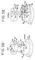
- passage 72 and its port 73 which align with the U-shaped bypass passage 52 in the valve plate 38 during the bypass operational mode, as seen in FIG. 5E.
- fluid discharged from the media is discharged (a) through the passage 49 in the valve plate 38 to the port 78 and discharge passage 79 for treated fluid from the valve housing 54 in the service operational mode, as seen in FIG.
- various blind seals 86-90 are positioned on the face 64 in the various positions seen in FIG. 5.
- Various passages in the valve plate 38 will align with these blind seals during certain operational modes. However, flow through those valve plate passages will be precluded because of the fact that these seals are blind.
- These respective blind seals 86-90 have only been numbered in the mode figures in which a passage in the valve plate 38 actually has been positioned so as to be in alignment with the particular blind seal in order to simplify the respective FIGS. 5A-5E.
- one of the media is an ion exchange medium
- a brine passage which is connected to a suitable brine supply (not shown) may be tapped into the passage 72.
- suitable check valves V are provided in the brine passage 72A and at the outlet from compartment to prevent back up of service supply water to the brine supply and/or brine to the service supply water in the compartment 68.
- the unit of the present invention is also constructed and arranged to produce frequent and immediate regeneration of the treatment medium 18 each time the unit is started up. This is advantageous where the unit is a counter top or under the counter unit for the treatment or other potable water supply, and even more advantageous where the unit is a showerhead unit because in that usage, the initial water flow is typically discarded anyway. In such uses, the water which is to be treated is typically turned on and off with some frequency. When off, no treatment of the water is taking place and when on, the water being consumed is undergoing treatment.
- the treatment medium is a finely divided copper-zinc metal, such as disclosed in the previously mentioned U.S. Patent No. 5,415,770
- These light contaminants will typically settle on the upper surface of the settled treatment medium bed 18 during shut down because they are substantially lighter and, therefore, will settle more slowly by gravity than the heavier metal particulates.
- these lighter solid contaminants will move away from the medium 18 at a much faster rate than the heavier metal particulate medium 18 will move, and the light contaminants will be flushed from the system.
- oxidization products such as the chloride salts from chlorine
- This removal of oxidants from the surface of the metal particles will greatly enhance the life span of the particulate metal medium to from as little as six months to one year to two to three years.
- this frequent regeneration permits a reduction in the amount of metal particulate medium needed to perform the same treatment of as much as 30-50%.
- the chamber 14 is tall and relatively narrow at its maximum width. This ensures that the flow rate through the chamber from the input end at support plate 24 to the fluid discharge through the slots 28 will be sufficient to permit medium 18 to be progressively suspended and agitated, as shown in FIGS. 3 and 4 upon start up of the unit so that the particles will aggressively abrade each other to remove the oxidation product coating thereon.
- the lifting of the particles is slowed and throttled.
- the bottom sleeve 91 is preferably a simple cylinder which at the top may be more or less crenelated to produce inlet orifices 94 for introducing inlet fluid to be treated at a higher elevation in the chamber 22 to enhance turbulence effect on the water treating medium 18, as seen by the arrows in FIGS. 3 and 4.
- the external diameter of the sleeve 91 preferably is slightly less than the internal diameter of the inner sidewall 22 of the chamber 14 to provide an annular channel 96 from the fluid inlet beneath plate 24 and upwardly about the sleeve 91 to the inlet orifices 94.
- the next upper sleeve 92 is also preferably somewhat less in external diameter than the interior diameter of the inner sidewall 22 so that an annular channel 97 is also provided to conduct inlet fluid further up the chamber to inlet orifices 98 between the top of sleeve 92 and the bottom of the uppermost sleeve 93.
- the principal purpose of the sleeves 92 and 93 is to provide one or more spaced shelves 99 which extend inwardly from the sidewall 22 of the chamber.
- Sleeves 99 provide substantially reduced cross sectional areas in the chamber 22 at spaced locations along the height of the chamber by way of apertures 100, as seen in FIGS. 1, 3 and 4, which are much narrower than the maximum cross-sectional area of the chamber 22. Without these apertures 100, the particulate medium 18 would become rapidly suspended at the top of the chamber 22 on start up and, thus, would not have the maximum ability to extensively abrade each other in close contact. However, the much smaller cross sectional area apertures 100 reduce the rate at which the particulate medium will ascend, and will produce a much more intimate relationship between the particles upon start up. These narrowed apertures 100, together with the orifices 94 and 98 which inject fluid adjacent these apertures, will result in substantial turbulence in the flow and suspension of the particulate water treatment medium 18, as seen in FIG. 3.
- the maximum diameter of the chamber 14 may vary widely, but will typically be anywhere between a fraction of an inch up to as much as foot or more. What is important is the relationship of the cross section area of the aperture 100 to the maximum cross-sectional area of the aperture 100 to the maximum cross-sectional of the chamber 22. This aperture area should be about 5-50% of the maximum cross-sectional area of the chamber 14, with about 10% preferred, to achieve the desired regeneration.
- the medium 20 in the outer chamber 16 may take any one of a number of forms. It may be an ion exchange resin for the removal of undesirable ions, such as a cationic resin for the removal of hardness from the water or an anionic resin for the removal of undesirable nitrates or organic contaminants. It may also be a particulate activated carbon for the removal of various odors, flavors or other organic contaminants as are well known in the art. Indeed, where the water treatment medium 20 is either an ion exchange resin or an activated carbon, the use of a particulate, finely divided metal as the upstream medium 18 can actually prolong the life of the later contacted medium by removing residual chlorine from the water, because chlorine has a deleterious effect on either an ion exchange medium or activated carbon.
- the fluid treatment unit 10 is shown in its at rest condition after a preceding treatment operation and awaiting start up for the next treatment operation.
- the unit In this condition, the unit is in its service operational mode as shown in FIG. 5A so that as soon as fluid flow is again initiated, for example of a municipal water supply, the unit is prepared to start its next treatment operation.
- the water treatment medium 18, for example the finely divided, particulate metal particles as disclosed and described in the aforementioned U.S. Patent No. 5,415,770 has settled to the bottom of the chamber 14 to form a relatively compact, condensed bed at the bottom of the chamber, as seen in FIG. 1.
- valve plate 38 In this at rest condition in which the unit is in its service operational mode, the valve plate 38 will have been rotated to the position A in FIG. 5A so that it is in the service position when fluid flow is reinitiated.
- the passage 48 in the valve plate 38 In this service position A, the passage 48 in the valve plate 38 is aligned with the passage 70 and its port 71 in the valve housing 54 in readiness to conduct the service fluid which is to be treated to the media for treatment when flow is reinitiated.
- Passage 49 in valve plate 38 is also aligned with port 78 and passage 79 in the valve housing 54 to conduct fluid from the media which has been treated to discharge it from the valve housing 54.
- the fluid When the flow of fluid is to be initiated for treatment, the fluid will enter the supply conduit 66 from the source of supply of the fluid (not shown), for example a municipal service supply of water, and the water will fill the compartment 68 in the bottom of the valve housing 54 under pressure. As best seen in FIG. 3, this fluid to be treated will then flow upwardly through passage 70 and port 71 in the valve housing 54, through the opening 34, through the space above the floor plate 32 in the chamber 14 and upwardly through the support plate 24 and mesh screen 26 into the fluid treatment medium 18.
- the source of supply of the fluid for example a municipal service supply of water
- This initial flow will commence the automatic cleaning of the medium 18 as previously described by flushing any loose, lighter contaminant solids which may have previously settled back onto the surface of the medium bed, upwardly and out through the vertical slots 28 at the top of chamber 14 for ultimate discharge from the unit. As shown in FIG. 3, this initial flow will also tend to displace the finely divided, particulate medium 18 in the bed upwardly from its previously settled, at rest position as shown in FIG. 1.
- the considerable agitation and turbulence in the particulate medium 18 upon start up will remove substantial percentages of the oxidation contamination products, for example the chloride salts from chlorine, which have previously accumulated on the surface of the particulate metal medium.
- This results in an automatic cleaning action which flushes these previously removed contaminants from the system upon at the beginning of each start up and presents a fresh metal surface on the particulate medium 18 which maximizes the removal of the undesirable oxidants in the next batch of fluid. to be treated. It has been found, for example, that 50-90% of the oxidation products which were previously coated upon the particulate metal surface of medium 18 will be removed within a few seconds following start up. This is particularly desirable for example in a shower head treatment installation in which the first several seconds of water flow is discarded anyway.
- the particulate medium 18 will eventually become suspended in the upper part of chamber 14, as viewed in FIG. 4, where it will continue to treat the continuing flow of water as it passes through that chamber. Once treated by the suspended particulate medium 18, the water will flow through the vertical slots 28 at the top of sidewall 22 and downwardly through the medium 20 in chamber 16.
- the medium 20 may take any one of a number of desired forms including various ion exchange resins and/or activated carbon.
- the treated water After passing through the medium 20 as depicted by the arrows in FIG. 4, the treated water will pass through the slotted openings 36 in the floor plate 32, and then through the mesh screen 42 and support plate 40, passage 49 in the valve plate 38, and port 78 and passage 79 in the valve housing to be discharged from the valve housing, as shown in FIG. 5A. Any extremely fine contaminants which also may pass through the slots 36 will accumulate on the very fine mesh screen 42 for later flushing, as will be described below. No flow will pass through passage 50 in the valve plate 38 because it is aligned with blind seal 86 on the face 64 of the valve housing 54 as seen in FIG. 5A. Moreover, there will be no flow through the U-shaped bypass 52, as viewed in FIG. 5A, because it is rotated to a nonoperative position in which its openings are aligned with non-functional, inactive locations on the face 64 of the valve housing 54, as shown in FIG. 5A.
- supply fluid will flow from the compartment 68 upwardly through passage 72, and its port 73, and through passage 49.
- This fluid will continue its flow reversely upwardly through the support plate 40 and mesh screen 42 to dislodge any fine particles which may have accumulated on that screen so that they may be flushed later through passage 50.
- Backflush flow will continue upwardly through slots 36 and the medium 20 in chamber 16, through the slots 28 at the top of chamber 14 and down through the bed of medium 18, the mesh screen 26 and support plate 24, through passage 48 in valve plate 38, as seen in FIG. 5B, and port 80 and passage 81 to drain where it is discharged and discarded.
- the backwashing fluid would preferably consist of a brine of sodium salts or potassium salts or the like for the regeneration of the ion exchange medium, rather than just simple water from a municipal service. supply.
- the brine will be introduced from a suitable source of brine (not shown) through passage 72A and into passage 72 where the brine flow will continue to flow as previously described in the backwash description, as shown in FIG. 5B.
- suitable check valves V will be included in passages 72 and 72A, as shown in FIGS. 5B and 5E, to preclude improper flow of fluids between the water supply and brine supply, or vice versa.
- passage 50 in the valve plate 38 is effectively immobilized because it is aligned with the blind seal 87 on the face 64 of the valve housing 54.
- the U-shaped bypass passage 52 in the valve plate 48 is also effectively immobilized because it is aligned with a non-functional, inactive area on the face 64 of the valve housing 54, as shown in FIG. 5B.
- the housing 12 with the valve plate 38 fixed thereto is simply further rotated to the flush position C as shown in FIG. 5C.
- passage 48 in the valve plate 38 is aligned with port 75 and passage 74 in the valve housing 54.
- Passage 74 communicates with the compartment 68 in the valve housing 54.
- Passage 50 in the valve plate 38 is aligned with port 82 and passage 83 to drain in the valve housing 54, as shown in FIG. 5C.
- supply fluid flows through the inlet 66, the compartment 68 and through passage 74 and port 75 in the valve housing 54, through the passage 48 in the valve plate 38, and to the media to flush the media.
- the fluid flow through the media is in the same direction as it is during the service mode as previously described.
- the fluid which leaves the media following flushing then flows into the chamber beneath floor plate 32 to flush any fines which may have been dislodged from mesh 42 through passage 50 in the valve plate 38 and port 82 and passage 83 in the valve housing 54 to be discharged to drain.
- the passage 49 in the valve plate 38 is immobilized because it is aligned with the blind seal 88 on the face 64 of the valve housing 54.
- the U-shaped bypass passage 52 is also immobilized because one of its ends is aligned with the blind seal 89 and the other end with a non-functional, inactive area on the face 64 of the valve housing 54, as seen in FIG. 5C.
- the entire unit may simply be turned off by further rotating the housing 12 and the valve plate 38 which is fixed to it to the off position D, as shown in FIG. 5D.
- all of the passages in the valve plate 38 are either aligned with nonfunctional, inactive areas on the face 64 of the valve housing 54 or with a drain discharge. More specifically, passages 48 and 49 as well as the U-shaped bypass passages 52 in valve plate 38 are aligned with non-functional, inactive areas on the face 64 of the valve housing 54 when the valve plate 38 is in the off position D.
- the only other passage 50 in the valve plate 38 is aligned with the bypass discharge port 84 and passage 85. Accordingly, no fluid flow occurs from or to the unit in this off position D.
- the housing 12 and valve plate 38 are rotated to the bypass position E, as shown in FIG. 5E.
- one leg of the U-shaped bypass passage 52 in valve plate 38 is aligned with passage 72 and port 73 on the valve housing 54 and the other leg of the U-shaped bypass passage 52 is aligned with port 84 and passage 85 in the valve housing 54.
- supply fluid will flow from the inlet 66 to compartment 68, through passage 72 and port 73 in the valve housing 54, through the U-shaped bypass passage 52 in the valve plate 38, and out through port 84 and passage 85 through a bypass discharge in valve housing 54. Any flow to the brine passage 72A will be blocked by its check valve V.
- valve plate 38 When the valve plate 38 is in the bypass position E and shown in FIG. 5E, the remaining passages through the valve plate 38 are immobilized. Passage 49 in valve plate 38 is aligned with blind seal 90, passage 50 is aligned with port 80 and drain passage 81 which is currently nonfunctional and inactive, and passage 48 in valve plate 38 is aligned with blind seal 89 on the face 64 of the valve housing 54.
Applications Claiming Priority (2)
| Application Number | Priority Date | Filing Date | Title |
|---|---|---|---|
| US09/165,830 US6042729A (en) | 1998-02-18 | 1998-10-02 | Regeneration of water treatment media |
| US165830 | 1998-10-02 |
Publications (3)
| Publication Number | Publication Date |
|---|---|
| EP0992459A2 true EP0992459A2 (de) | 2000-04-12 |
| EP0992459A3 EP0992459A3 (de) | 2000-07-12 |
| EP0992459B1 EP0992459B1 (de) | 2005-11-16 |
Family
ID=22600656
Family Applications (1)
| Application Number | Title | Priority Date | Filing Date |
|---|---|---|---|
| EP99118764A Expired - Lifetime EP0992459B1 (de) | 1998-10-02 | 1999-09-23 | Wasserbehandlungsvorrichtung mit Regeneration des darin enthaltenen Behandlungsmediums |
Country Status (9)
| Country | Link |
|---|---|
| US (3) | US6042729A (de) |
| EP (1) | EP0992459B1 (de) |
| JP (1) | JP2000107751A (de) |
| KR (1) | KR100478548B1 (de) |
| CN (2) | CN100334004C (de) |
| AT (1) | ATE309962T1 (de) |
| CA (1) | CA2283056C (de) |
| DE (1) | DE69928348T2 (de) |
| HK (1) | HK1027087A1 (de) |
Cited By (3)
| Publication number | Priority date | Publication date | Assignee | Title |
|---|---|---|---|---|
| DE102004049876A1 (de) * | 2004-10-13 | 2006-04-20 | Brita Gmbh | Filterkartusche |
| EP1834927A1 (de) | 2006-03-17 | 2007-09-19 | Aquis Wasser-Luft-Systeme GmbH, Lindau | Vorrichtung zur Wasseraufbereitung mit Verschnittvorrichtung |
| ES2334317A1 (es) * | 2008-09-05 | 2010-03-08 | Valvules I Racords Canovelles, S.A. | "dispositivo para la distribucion controlada de liquidos". |
Families Citing this family (43)
| Publication number | Priority date | Publication date | Assignee | Title |
|---|---|---|---|---|
| US6042729A (en) * | 1998-02-18 | 2000-03-28 | Chau; Yiu Chau | Regeneration of water treatment media |
| DE19962169C2 (de) * | 1999-12-22 | 2002-05-23 | Steag Micro Tech Gmbh | Vorrichtung zum Behandeln von Substraten |
| US7135146B2 (en) * | 2000-10-11 | 2006-11-14 | Innovadyne Technologies, Inc. | Universal non-contact dispense peripheral apparatus and method for a primary liquid handling device |
| US6852291B1 (en) * | 2000-10-11 | 2005-02-08 | Innovadyne Technologies, Inc. | Hybrid valve apparatus and method for fluid handling |
| US6557573B2 (en) * | 2001-02-06 | 2003-05-06 | Pgi International, Ltd. | Liquid fertilizer distribution system and method |
| US6797156B2 (en) | 2001-12-21 | 2004-09-28 | Yiu Chau Chau | Faucet water treatment |
| US7169616B2 (en) * | 2002-01-25 | 2007-01-30 | Innovadyne Technologies, Inc. | Method of purging trapped gas from a system fluid contained in an actuation valve |
| US7156995B2 (en) * | 2002-03-04 | 2007-01-02 | Hellenbrand, Inc. | Aeration tank control valve system |
| US20030222013A1 (en) * | 2002-06-03 | 2003-12-04 | Yang Vue X. | Method and apparatus for preventing microbial growth in drinking water |
| US20040050769A1 (en) * | 2002-09-16 | 2004-03-18 | Sheng Henry P. | Liquid mixture separators |
| US20050126974A1 (en) * | 2003-12-15 | 2005-06-16 | Harusuke Naito | Water purifier having magnetic field generation |
| WO2005074508A2 (en) * | 2004-01-30 | 2005-08-18 | Ljc Technologies, L.L.C. | Molecular separator |
| US7291267B2 (en) * | 2004-01-30 | 2007-11-06 | Ljc Technologies, L.L.C. | Molecular separator |
| US8012355B2 (en) * | 2004-01-30 | 2011-09-06 | Pss Acquisitionco Llc | Molecular separator |
| US7906023B2 (en) * | 2005-01-25 | 2011-03-15 | Pss Acquisitionco Llc | Wastewater treatment method and apparatus |
| US7427355B2 (en) * | 2004-05-14 | 2008-09-23 | Yiu Chau Chau | Water treatment unit for bottle or pitcher |
| WO2006071256A2 (en) * | 2004-05-18 | 2006-07-06 | Basin Water, Inc. | Perchlorate removal process |
| DE102004049877B4 (de) * | 2004-10-13 | 2008-03-27 | Brita Gmbh | Filterkartusche und Sitzelement für eine Filterkartusche |
| US20060213825A1 (en) * | 2005-03-28 | 2006-09-28 | Dave Averbeck | Modular water treatment unit |
| US20060231462A1 (en) * | 2005-04-15 | 2006-10-19 | Johnson Raymond F | System for improving crude oil |
| EP2007683B1 (de) * | 2006-04-05 | 2018-05-23 | Aquis Wasser-Luft-Systeme GmbH, Lindau | Wasserfilter-kartuschensystem mit kombinierter verschneideventiltechnik und einstellvorrichtung in der kerze und im kopf |
| DE102006044746B4 (de) * | 2006-04-05 | 2021-09-23 | Aquis Wasser-Luft-Systeme Gmbh, Lindau, Zweigniederlassung Rebstein | Wasserfilter mit Verschneidevorrichtung |
| DE202006010015U1 (de) * | 2006-06-26 | 2006-08-24 | Judo Wasseraufbereitung Gmbh | Rückspülbarer Wasserfilter |
| US7491321B1 (en) | 2006-07-18 | 2009-02-17 | Hellenbrand, Inc. | Oxidation tank control valve assembly and systems and methods for replenishing a charge of oxygen-containing gas within an oxidation tank |
| CN101152609B (zh) * | 2006-09-25 | 2010-09-08 | 北京科净源科技股份有限公司 | 浮动床过滤器 |
| US7837866B2 (en) * | 2006-10-12 | 2010-11-23 | Burrows Bruce D | Drainless reverse osmosis water purification system |
| US8398852B2 (en) * | 2006-10-12 | 2013-03-19 | Bruce D. Burrows | Drainless reverse osmosis water purification system |
| US9371245B2 (en) | 2006-10-12 | 2016-06-21 | Bruce D. Burrows | Drainless reverse osmosis water purification system |
| CN101224353B (zh) * | 2007-10-22 | 2011-09-14 | 宛金晖 | 可反冲清污的浮动上滤式过滤器的使用方法 |
| CN102190337B (zh) | 2010-03-05 | 2014-09-03 | 周耀周 | 具有手动切换机构的流体处理装置 |
| WO2012047892A2 (en) * | 2010-10-04 | 2012-04-12 | Calgon Carbon Corporation | Fluid-directing multiport rotary apparatus |
| US10766010B2 (en) | 2011-10-20 | 2020-09-08 | Henderson Products, Inc. | High throughput brine generating system |
| US10544340B2 (en) | 2011-10-20 | 2020-01-28 | Henderson Products, Inc. | Brine generation system |
| US8864998B1 (en) * | 2012-10-31 | 2014-10-21 | Al Siamon | Bead fluid treatment self-cleaning apparatus and method |
| US10183874B2 (en) | 2013-12-18 | 2019-01-22 | Ds Services Of America, Inc. | Water purification system with active vibration |
| DK3283801T3 (da) * | 2015-04-14 | 2020-11-02 | Keofitt As | Prøvetagningsindretning til udtagning af fluidprøver fra en fluidbeholder |
| CH711523B1 (de) * | 2015-09-15 | 2019-02-15 | Elysator Genossenschaft | Behälter für eine Filterkartusche sowie Filtersatz. |
| US11725781B2 (en) | 2019-02-11 | 2023-08-15 | Watts Regulator Co. | Pressure relief cover assembly |
| US11333264B2 (en) | 2019-02-11 | 2022-05-17 | Watts Regulator Co. | Manifold assembly for a water filter system |
| US11471794B2 (en) | 2019-02-11 | 2022-10-18 | Watts Regulator Co. | Filter cartridge for a whole house water filtering system |
| US11000540B1 (en) | 2019-11-22 | 2021-05-11 | Al Siamon | Treatment for reducing adverse events including chemotherapy discomfort and other conditions |
| US11253595B2 (en) | 2019-11-22 | 2022-02-22 | Al Siamon | Treatment for reducing adverse events including chemotherapy discomfort and other conditions |
| CN111547876A (zh) * | 2020-04-10 | 2020-08-18 | 广东工业大学 | 一种可同步去除水中硬度、余氯及致病微生物的新型淋浴净水花洒 |
Citations (11)
| Publication number | Priority date | Publication date | Assignee | Title |
|---|---|---|---|---|
| DE832596C (de) * | 1950-10-21 | 1952-02-25 | Metallgesellschaft Ag | Vorrichtung zur Behandlung von Fluessigkeiten mit koernigen Filtermaterialien |
| BE714478A (de) * | 1968-04-30 | 1968-09-16 | ||
| US4115276A (en) * | 1977-04-04 | 1978-09-19 | Purex Corporation | Multi-port backwash valve |
| GB2174920A (en) * | 1985-05-17 | 1986-11-19 | Vehashkaya Amiad Sinun | Irrigation water filter |
| US4814078A (en) * | 1987-09-15 | 1989-03-21 | Associated Mills Inc. | Water filter cartridge |
| US5164082A (en) * | 1991-12-17 | 1992-11-17 | Lin Tzu Fu | Water filter having lever controlled plunger |
| US5340478A (en) * | 1992-08-07 | 1994-08-23 | International Purity Corp. | Dual chamber water filter |
| EP0720862A1 (de) * | 1995-01-07 | 1996-07-10 | Bossert, Gerdi | Siebfilter für flüssige oder gasförmige Medien |
| US5628900A (en) * | 1995-10-18 | 1997-05-13 | Naito; Harusuke | Water purifier having a magnetic field generation device |
| US5643444A (en) * | 1994-01-10 | 1997-07-01 | Seb S.A. | Device for filtering a liquid, particularly water |
| DE19827623A1 (de) * | 1997-07-04 | 1999-01-07 | Aweco Kunststofftech Geraete | Wasserbehälter mit Filterpatrone |
Family Cites Families (35)
| Publication number | Priority date | Publication date | Assignee | Title |
|---|---|---|---|---|
| US171056A (en) * | 1875-12-14 | Improvement in apparatus for filtering liquids | ||
| US197368A (en) * | 1877-11-20 | Eiqhajtdgoky | ||
| US163814A (en) * | 1875-05-25 | Improvement in apparatus for filtering liquids | ||
| US1443794A (en) * | 1918-01-03 | 1923-01-30 | Purposed Mind Dev Security | Suction means for feeding powdered fuel to fire boxes |
| US1671699A (en) * | 1927-10-21 | 1928-05-29 | Ward Love Pump Corp | Water softener |
| US1951917A (en) * | 1932-03-05 | 1934-03-20 | Leslie Francis | Water softener or filter |
| US2101961A (en) * | 1934-10-31 | 1937-12-14 | Burgess Lab Inc C F | Treatment of water |
| DE1442689C3 (de) * | 1963-11-29 | 1978-11-30 | Bayer Ag, 5090 Leverkusen | Verfahren zur Behandlung von Flüssigkeiten mit Ionenaustauschern |
| US3523762A (en) * | 1967-05-19 | 1970-08-11 | Universal Oil Prod Co | Baffled chamber for a plurality of contact beds to preclude diffused fluid flow |
| US4196081A (en) | 1978-04-13 | 1980-04-01 | Pavia Edgar H | Apparatus for emergency water purification |
| FR2501069B1 (fr) * | 1981-03-05 | 1985-08-02 | Scumra | Procede et dispositif d'extraction d'ions d'un liquide clair ou contenant des matieres en suspension par mise en contact avec un echangeur |
| US5415770A (en) * | 1984-04-30 | 1995-05-16 | Kdf Fluid Treatment, Inc. | Apparatus for treating fluids |
| US4642192A (en) * | 1984-04-30 | 1987-02-10 | Heskett Don E | Method of treating fluids |
| US5135654A (en) | 1984-04-30 | 1992-08-04 | Kdf Fluid Treatment, Inc. | Method for treating fluids |
| CN1004193B (zh) * | 1985-04-01 | 1989-05-17 | 兰州铁路局科学技术研究所 | 连续式离子交换处理方法 |
| CN85201787U (zh) * | 1985-04-30 | 1986-03-19 | 长沙市锅炉水处理设备厂 | 多路转阀浮动床水处理设备 |
| CN86206818U (zh) * | 1986-09-13 | 1987-12-12 | 陈绍维 | 多路旋塞阀满罐水软化处理设备 |
| CN87203183U (zh) * | 1987-04-15 | 1988-01-06 | 刘宗高 | 锅炉用软水器多功能分流阀 |
| JPH0379891U (de) * | 1989-11-30 | 1991-08-15 | ||
| US5041219A (en) * | 1990-02-12 | 1991-08-20 | Strand Charles D | Dual chamber water filter |
| CH681685A5 (de) * | 1990-11-02 | 1993-05-14 | Eldom Rothrist Ag | |
| JP2523223B2 (ja) | 1990-11-30 | 1996-08-07 | けい子 川上 | ろ過器用の切換え弁装置 |
| US5149437A (en) * | 1991-03-29 | 1992-09-22 | Wilkinson Theodore L | Water filter |
| US5205932A (en) * | 1991-08-22 | 1993-04-27 | Nu-Water Systems, Inc. | Point-of-use water purification appliance |
| US5171442A (en) * | 1991-10-18 | 1992-12-15 | Nakshbendi Ghassan F | Water purification apparatus |
| US5242589A (en) * | 1991-12-16 | 1993-09-07 | Cheng-Wei Hsu | Filter that changes the direction of water current arbitrarily |
| JP2706749B2 (ja) | 1992-10-28 | 1998-01-28 | けい子 川上 | 浄水器の切換え弁装置 |
| CN2163808Y (zh) * | 1993-03-25 | 1994-05-04 | 西安航联技术发展部 | 带平面多功能集成阀的全自动钠离子交换器 |
| US5573665A (en) * | 1995-02-02 | 1996-11-12 | Purotech Ltd. | Three chamber consecutive flow water treatment device |
| US5628990A (en) | 1995-10-25 | 1997-05-13 | Church & Dwight Co., Inc. | Anhydrous cosmetic product containing deodorant and desiccant ingredients |
| US5989425A (en) * | 1995-11-17 | 1999-11-23 | Toray Industries, Inc. | Multi-way valve and water purifier using the same |
| US5879565A (en) * | 1996-11-04 | 1999-03-09 | Kusmierz; Joel E. | Cooling tower water treatment system |
| US5785848A (en) * | 1996-12-06 | 1998-07-28 | Strand; Charles D. | Rectangular body water purification device |
| IT1295473B1 (it) * | 1997-10-06 | 1999-05-12 | Gevipi Ag | Valvola di intercettazione o di deviazione a piu' vie. |
| US6042729A (en) * | 1998-02-18 | 2000-03-28 | Chau; Yiu Chau | Regeneration of water treatment media |
-
1998
- 1998-10-02 US US09/165,830 patent/US6042729A/en not_active Expired - Lifetime
-
1999
- 1999-09-23 DE DE1999628348 patent/DE69928348T2/de not_active Expired - Lifetime
- 1999-09-23 AT AT99118764T patent/ATE309962T1/de not_active IP Right Cessation
- 1999-09-23 CA CA 2283056 patent/CA2283056C/en not_active Expired - Fee Related
- 1999-09-23 EP EP99118764A patent/EP0992459B1/de not_active Expired - Lifetime
- 1999-09-29 CN CNB991205332A patent/CN100334004C/zh not_active Expired - Fee Related
- 1999-09-29 CN CN2007101122595A patent/CN101092253B/zh not_active Expired - Fee Related
- 1999-10-02 KR KR10-1999-0042462A patent/KR100478548B1/ko not_active IP Right Cessation
- 1999-10-04 JP JP28270999A patent/JP2000107751A/ja active Pending
-
2000
- 2000-02-24 US US09/511,933 patent/US6231763B1/en not_active Expired - Lifetime
- 2000-10-05 HK HK00106320A patent/HK1027087A1/xx not_active IP Right Cessation
-
2001
- 2001-03-13 US US09/808,161 patent/US6447678B2/en not_active Expired - Fee Related
Patent Citations (11)
| Publication number | Priority date | Publication date | Assignee | Title |
|---|---|---|---|---|
| DE832596C (de) * | 1950-10-21 | 1952-02-25 | Metallgesellschaft Ag | Vorrichtung zur Behandlung von Fluessigkeiten mit koernigen Filtermaterialien |
| BE714478A (de) * | 1968-04-30 | 1968-09-16 | ||
| US4115276A (en) * | 1977-04-04 | 1978-09-19 | Purex Corporation | Multi-port backwash valve |
| GB2174920A (en) * | 1985-05-17 | 1986-11-19 | Vehashkaya Amiad Sinun | Irrigation water filter |
| US4814078A (en) * | 1987-09-15 | 1989-03-21 | Associated Mills Inc. | Water filter cartridge |
| US5164082A (en) * | 1991-12-17 | 1992-11-17 | Lin Tzu Fu | Water filter having lever controlled plunger |
| US5340478A (en) * | 1992-08-07 | 1994-08-23 | International Purity Corp. | Dual chamber water filter |
| US5643444A (en) * | 1994-01-10 | 1997-07-01 | Seb S.A. | Device for filtering a liquid, particularly water |
| EP0720862A1 (de) * | 1995-01-07 | 1996-07-10 | Bossert, Gerdi | Siebfilter für flüssige oder gasförmige Medien |
| US5628900A (en) * | 1995-10-18 | 1997-05-13 | Naito; Harusuke | Water purifier having a magnetic field generation device |
| DE19827623A1 (de) * | 1997-07-04 | 1999-01-07 | Aweco Kunststofftech Geraete | Wasserbehälter mit Filterpatrone |
Cited By (7)
| Publication number | Priority date | Publication date | Assignee | Title |
|---|---|---|---|---|
| DE102004049876A1 (de) * | 2004-10-13 | 2006-04-20 | Brita Gmbh | Filterkartusche |
| DE102004049876B4 (de) * | 2004-10-13 | 2008-03-27 | Brita Gmbh | Filterkartusche |
| DE102004049876C5 (de) * | 2004-10-13 | 2010-04-29 | Brita Gmbh | Filterkartusche |
| EP1802224B2 (de) † | 2004-10-13 | 2010-08-25 | Brita GmbH | Filterkartusche |
| US9023205B2 (en) | 2004-10-13 | 2015-05-05 | Brita Gmbh | Filter cartridge |
| EP1834927A1 (de) | 2006-03-17 | 2007-09-19 | Aquis Wasser-Luft-Systeme GmbH, Lindau | Vorrichtung zur Wasseraufbereitung mit Verschnittvorrichtung |
| ES2334317A1 (es) * | 2008-09-05 | 2010-03-08 | Valvules I Racords Canovelles, S.A. | "dispositivo para la distribucion controlada de liquidos". |
Also Published As
| Publication number | Publication date |
|---|---|
| CN101092253A (zh) | 2007-12-26 |
| US6447678B2 (en) | 2002-09-10 |
| KR100478548B1 (ko) | 2005-03-23 |
| HK1027087A1 (en) | 2001-01-05 |
| DE69928348T2 (de) | 2006-08-03 |
| CN101092253B (zh) | 2010-12-22 |
| ATE309962T1 (de) | 2005-12-15 |
| US6231763B1 (en) | 2001-05-15 |
| CA2283056C (en) | 2007-07-10 |
| DE69928348D1 (de) | 2005-12-22 |
| EP0992459A3 (de) | 2000-07-12 |
| CA2283056A1 (en) | 2000-04-02 |
| CN100334004C (zh) | 2007-08-29 |
| EP0992459B1 (de) | 2005-11-16 |
| US6042729A (en) | 2000-03-28 |
| CN1250748A (zh) | 2000-04-19 |
| JP2000107751A (ja) | 2000-04-18 |
| US20010009237A1 (en) | 2001-07-26 |
| KR20000028789A (ko) | 2000-05-25 |
Similar Documents
| Publication | Publication Date | Title |
|---|---|---|
| US6042729A (en) | Regeneration of water treatment media | |
| US6254772B1 (en) | Backwashable filtration system | |
| KR100229989B1 (ko) | 가공폐액 재생방법 및 가공폐액 재생장치 | |
| JP4954276B2 (ja) | 大量流動液体から粒子および生物を分離および濾過する装置および方法 | |
| JP2000107751A5 (de) | ||
| US5833867A (en) | System and method for backwashing multiple filtration vessels | |
| US20060272999A1 (en) | Method and apparatus for a water filter backflush | |
| US5178773A (en) | High efficiency filter to remove suspended solids from aqueous media | |
| US20040074836A1 (en) | Eductor circulated nut shell media filter | |
| KR100626405B1 (ko) | 규조토를 이용한 정화시스템의 여과기 | |
| CA2256858C (en) | Tank treatment assembly | |
| CA2265235A1 (en) | Multimedia backwashable filtration system | |
| JP4029263B2 (ja) | 複合精密ろ過方法並びにろ過装置 | |
| US20160101991A1 (en) | Eductor circulated nutshell media water filter | |
| JP2022026485A (ja) | 水浄化装置 | |
| KR20230121234A (ko) | 여과 장치 | |
| GB2161712A (en) | Plating machine filter | |
| JP2021186757A (ja) | 水浄化装置 | |
| IL272438B2 (en) | Self-cleaning filter system and method | |
| JPH04176327A (ja) | 中空糸膜濾過方法および中空糸膜濾過装置 | |
| JPH10249371A (ja) | 浄化槽及びその洗浄方法 | |
| US20040217066A1 (en) | Universal piping apparatus for use with a filtration device | |
| JPH1080692A (ja) | 逆洗装置付き汚水処理装置 | |
| JPS61268308A (ja) | 被処理液の濾過方法 | |
| JPH04131192A (ja) | 生物濾過装置 |
Legal Events
| Date | Code | Title | Description |
|---|---|---|---|
| PUAI | Public reference made under article 153(3) epc to a published international application that has entered the european phase |
Free format text: ORIGINAL CODE: 0009012 |
|
| AK | Designated contracting states |
Kind code of ref document: A2 Designated state(s): AT BE CH CY DE DK ES FI FR GB GR IE IT LI LU MC NL PT SE |
|
| AX | Request for extension of the european patent |
Free format text: AL;LT;LV;MK;RO;SI |
|
| RAP1 | Party data changed (applicant data changed or rights of an application transferred) |
Owner name: CHAU CHAU, YIU |
|
| RIN1 | Information on inventor provided before grant (corrected) |
Inventor name: CHAU CHAU, YIU |
|
| PUAL | Search report despatched |
Free format text: ORIGINAL CODE: 0009013 |
|
| AK | Designated contracting states |
Kind code of ref document: A3 Designated state(s): AT BE CH CY DE DK ES FI FR GB GR IE IT LI LU MC NL PT SE |
|
| AX | Request for extension of the european patent |
Free format text: AL;LT;LV;MK;RO;SI |
|
| 17P | Request for examination filed |
Effective date: 20010110 |
|
| AKX | Designation fees paid |
Free format text: AT BE CH CY DE DK ES FI FR GB GR IE IT LI LU MC NL PT SE |
|
| 17Q | First examination report despatched |
Effective date: 20030721 |
|
| GRAP | Despatch of communication of intention to grant a patent |
Free format text: ORIGINAL CODE: EPIDOSNIGR1 |
|
| RTI1 | Title (correction) |
Free format text: WATER TREATMENT DEVICE WITH REGENERATION OF THE TREATMENT MEDIUM THEREIN |
|
| GRAS | Grant fee paid |
Free format text: ORIGINAL CODE: EPIDOSNIGR3 |
|
| GRAA | (expected) grant |
Free format text: ORIGINAL CODE: 0009210 |
|
| AK | Designated contracting states |
Kind code of ref document: B1 Designated state(s): AT BE CH DE DK ES FR GB GR IE IT LI NL PT SE |
|
| PG25 | Lapsed in a contracting state [announced via postgrant information from national office to epo] |
Ref country code: NL Free format text: LAPSE BECAUSE OF FAILURE TO SUBMIT A TRANSLATION OF THE DESCRIPTION OR TO PAY THE FEE WITHIN THE PRESCRIBED TIME-LIMIT Effective date: 20051116 Ref country code: LI Free format text: LAPSE BECAUSE OF FAILURE TO SUBMIT A TRANSLATION OF THE DESCRIPTION OR TO PAY THE FEE WITHIN THE PRESCRIBED TIME-LIMIT Effective date: 20051116 Ref country code: CH Free format text: LAPSE BECAUSE OF FAILURE TO SUBMIT A TRANSLATION OF THE DESCRIPTION OR TO PAY THE FEE WITHIN THE PRESCRIBED TIME-LIMIT Effective date: 20051116 Ref country code: BE Free format text: LAPSE BECAUSE OF FAILURE TO SUBMIT A TRANSLATION OF THE DESCRIPTION OR TO PAY THE FEE WITHIN THE PRESCRIBED TIME-LIMIT Effective date: 20051116 Ref country code: AT Free format text: LAPSE BECAUSE OF FAILURE TO SUBMIT A TRANSLATION OF THE DESCRIPTION OR TO PAY THE FEE WITHIN THE PRESCRIBED TIME-LIMIT Effective date: 20051116 |
|
| REG | Reference to a national code |
Ref country code: GB Ref legal event code: FG4D |
|
| REG | Reference to a national code |
Ref country code: CH Ref legal event code: EP |
|
| REG | Reference to a national code |
Ref country code: IE Ref legal event code: FG4D |
|
| REF | Corresponds to: |
Ref document number: 69928348 Country of ref document: DE Date of ref document: 20051222 Kind code of ref document: P |
|
| PG25 | Lapsed in a contracting state [announced via postgrant information from national office to epo] |
Ref country code: SE Free format text: LAPSE BECAUSE OF FAILURE TO SUBMIT A TRANSLATION OF THE DESCRIPTION OR TO PAY THE FEE WITHIN THE PRESCRIBED TIME-LIMIT Effective date: 20060216 Ref country code: GR Free format text: LAPSE BECAUSE OF FAILURE TO SUBMIT A TRANSLATION OF THE DESCRIPTION OR TO PAY THE FEE WITHIN THE PRESCRIBED TIME-LIMIT Effective date: 20060216 Ref country code: DK Free format text: LAPSE BECAUSE OF FAILURE TO SUBMIT A TRANSLATION OF THE DESCRIPTION OR TO PAY THE FEE WITHIN THE PRESCRIBED TIME-LIMIT Effective date: 20060216 |
|
| PG25 | Lapsed in a contracting state [announced via postgrant information from national office to epo] |
Ref country code: ES Free format text: LAPSE BECAUSE OF FAILURE TO SUBMIT A TRANSLATION OF THE DESCRIPTION OR TO PAY THE FEE WITHIN THE PRESCRIBED TIME-LIMIT Effective date: 20060227 |
|
| PG25 | Lapsed in a contracting state [announced via postgrant information from national office to epo] |
Ref country code: PT Free format text: LAPSE BECAUSE OF FAILURE TO SUBMIT A TRANSLATION OF THE DESCRIPTION OR TO PAY THE FEE WITHIN THE PRESCRIBED TIME-LIMIT Effective date: 20060417 |
|
| NLV1 | Nl: lapsed or annulled due to failure to fulfill the requirements of art. 29p and 29m of the patents act | ||
| REG | Reference to a national code |
Ref country code: HK Ref legal event code: GR Ref document number: 1027087 Country of ref document: HK |
|
| REG | Reference to a national code |
Ref country code: CH Ref legal event code: PL |
|
| ET | Fr: translation filed | ||
| PLBE | No opposition filed within time limit |
Free format text: ORIGINAL CODE: 0009261 |
|
| STAA | Information on the status of an ep patent application or granted ep patent |
Free format text: STATUS: NO OPPOSITION FILED WITHIN TIME LIMIT |
|
| PG25 | Lapsed in a contracting state [announced via postgrant information from national office to epo] |
Ref country code: IE Free format text: LAPSE BECAUSE OF NON-PAYMENT OF DUE FEES Effective date: 20060925 |
|
| 26N | No opposition filed |
Effective date: 20060817 |
|
| REG | Reference to a national code |
Ref country code: IE Ref legal event code: MM4A |
|
| PGFP | Annual fee paid to national office [announced via postgrant information from national office to epo] |
Ref country code: GB Payment date: 20090929 Year of fee payment: 11 |
|
| PGFP | Annual fee paid to national office [announced via postgrant information from national office to epo] |
Ref country code: IT Payment date: 20090928 Year of fee payment: 11 |
|
| PGFP | Annual fee paid to national office [announced via postgrant information from national office to epo] |
Ref country code: FR Payment date: 20100930 Year of fee payment: 12 |
|
| PGFP | Annual fee paid to national office [announced via postgrant information from national office to epo] |
Ref country code: DE Payment date: 20100929 Year of fee payment: 12 |
|
| GBPC | Gb: european patent ceased through non-payment of renewal fee |
Effective date: 20100923 |
|
| PG25 | Lapsed in a contracting state [announced via postgrant information from national office to epo] |
Ref country code: IT Free format text: LAPSE BECAUSE OF NON-PAYMENT OF DUE FEES Effective date: 20100923 |
|
| PG25 | Lapsed in a contracting state [announced via postgrant information from national office to epo] |
Ref country code: GB Free format text: LAPSE BECAUSE OF NON-PAYMENT OF DUE FEES Effective date: 20100923 |
|
| REG | Reference to a national code |
Ref country code: FR Ref legal event code: ST Effective date: 20120531 |
|
| REG | Reference to a national code |
Ref country code: DE Ref legal event code: R119 Ref document number: 69928348 Country of ref document: DE Effective date: 20120403 |
|
| PG25 | Lapsed in a contracting state [announced via postgrant information from national office to epo] |
Ref country code: DE Free format text: LAPSE BECAUSE OF NON-PAYMENT OF DUE FEES Effective date: 20120403 |
|
| PG25 | Lapsed in a contracting state [announced via postgrant information from national office to epo] |
Ref country code: FR Free format text: LAPSE BECAUSE OF NON-PAYMENT OF DUE FEES Effective date: 20110930 |