EP0990769B1 - Procédé de fabrication d'un cylindre comportant une extension longitudinale - Google Patents
Procédé de fabrication d'un cylindre comportant une extension longitudinale Download PDFInfo
- Publication number
- EP0990769B1 EP0990769B1 EP99250342A EP99250342A EP0990769B1 EP 0990769 B1 EP0990769 B1 EP 0990769B1 EP 99250342 A EP99250342 A EP 99250342A EP 99250342 A EP99250342 A EP 99250342A EP 0990769 B1 EP0990769 B1 EP 0990769B1
- Authority
- EP
- European Patent Office
- Prior art keywords
- die
- block
- dome
- section
- machined
- Prior art date
- Legal status (The legal status is an assumption and is not a legal conclusion. Google has not performed a legal analysis and makes no representation as to the accuracy of the status listed.)
- Expired - Lifetime
Links
Images


Classifications
-
- B—PERFORMING OPERATIONS; TRANSPORTING
- B21—MECHANICAL METAL-WORKING WITHOUT ESSENTIALLY REMOVING MATERIAL; PUNCHING METAL
- B21C—MANUFACTURE OF METAL SHEETS, WIRE, RODS, TUBES OR PROFILES, OTHERWISE THAN BY ROLLING; AUXILIARY OPERATIONS USED IN CONNECTION WITH METAL-WORKING WITHOUT ESSENTIALLY REMOVING MATERIAL
- B21C23/00—Extruding metal; Impact extrusion
- B21C23/02—Making uncoated products
- B21C23/20—Making uncoated products by backward extrusion
- B21C23/205—Making products of generally elongated shape
-
- B—PERFORMING OPERATIONS; TRANSPORTING
- B23—MACHINE TOOLS; METAL-WORKING NOT OTHERWISE PROVIDED FOR
- B23P—METAL-WORKING NOT OTHERWISE PROVIDED FOR; COMBINED OPERATIONS; UNIVERSAL MACHINE TOOLS
- B23P15/00—Making specific metal objects by operations not covered by a single other subclass or a group in this subclass
-
- Y—GENERAL TAGGING OF NEW TECHNOLOGICAL DEVELOPMENTS; GENERAL TAGGING OF CROSS-SECTIONAL TECHNOLOGIES SPANNING OVER SEVERAL SECTIONS OF THE IPC; TECHNICAL SUBJECTS COVERED BY FORMER USPC CROSS-REFERENCE ART COLLECTIONS [XRACs] AND DIGESTS
- Y10—TECHNICAL SUBJECTS COVERED BY FORMER USPC
- Y10T—TECHNICAL SUBJECTS COVERED BY FORMER US CLASSIFICATION
- Y10T29/00—Metal working
- Y10T29/49—Method of mechanical manufacture
- Y10T29/49229—Prime mover or fluid pump making
- Y10T29/4927—Cylinder, cylinder head or engine valve sleeve making
- Y10T29/49272—Cylinder, cylinder head or engine valve sleeve making with liner, coating, or sleeve
-
- Y—GENERAL TAGGING OF NEW TECHNOLOGICAL DEVELOPMENTS; GENERAL TAGGING OF CROSS-SECTIONAL TECHNOLOGIES SPANNING OVER SEVERAL SECTIONS OF THE IPC; TECHNICAL SUBJECTS COVERED BY FORMER USPC CROSS-REFERENCE ART COLLECTIONS [XRACs] AND DIGESTS
- Y10—TECHNICAL SUBJECTS COVERED BY FORMER USPC
- Y10T—TECHNICAL SUBJECTS COVERED BY FORMER US CLASSIFICATION
- Y10T29/00—Metal working
- Y10T29/49—Method of mechanical manufacture
- Y10T29/4998—Combined manufacture including applying or shaping of fluent material
- Y10T29/49982—Coating
Definitions
- the invention relates to a method for producing a cylinder with at least an outward and over the length extending bulge and with a Steel floor for a piston-cylinder unit.
- This object is achieved according to the invention by a method for producing a Cylinder with at least one outward and over the length extending Bulge and with a steel floor for a piston-cylinder unit through Extruding a metal block heated to forming temperature over a dome, with a puffed round ingot or round cast block before heating up Forming temperature between 1250 ° C and 1310 ° C mechanically machined to measure and after heating, the entire surface of the insert with press water is descaled and then the prepared metal block in a with a with the Bulge provided complementary cavity provided matrix and by means of the Domes in one operation to form a hole piece with a bottom strong is punched ascending, wherein before punching on the female and the dome Lubricant is applied, then the bottomed hole piece ejected from the die, cooled and descaled and finally mechanically finished.
- a puffed round ingot or a Rundstranggußblock is mechanically machined to a temperature between 1250 and 1310 ° C before heating, preferably by turning with a roughness of R z ⁇ 80.
- the entire surface with press water at 300 ⁇ 10 5 Pa descaled and the block after use in die by means of a thorn perforated sharply rising.
- the block is lengthened by at least 1.5-fold to 2.5-fold, based on the initial length.
- the thorn does not pierce the block, but leaves a floor.
- a lubricant is applied to the matrix and the dome. This is preferably a mixed with water glass mixture of glass powder and pure graphite in the ratio 1: 1.
- the outer surface is descaled after cooling. Finally, a mechanical processing. Depending on the material and requirement, a heat treatment may be necessary, which takes place after the hole has been pushed out of the die and before descaling. Preferably, the heat treatment is a water treatment.
- the die is arranged vertically, but also a horizontal position is possible.
- the advantage of the strongly increasing punching is that the material also displaces radially is, so that the bulges forming the cavity of the die over a sufficient length to be fully filled.
- Condition is that the dome almost center-centric on the block is placed. Too large deviations lead to Committee, as the bulge is only partially filled.
- the exact center of the Dornes is determined in such a way that the dome in the cold state a piece in the Retracted die and radially the distance to the die is measured.
- radial displacement of the die is a precise Einjust réelle.
- For support a centering of the mandrel is a portion of the insert block to a cylindrical and the second section to a conical body mechanically machined, this section is inserted into the die.
- the Diameter tolerance of the two sections is in the plus range, so that a centering insertion of the block is ensured in the die.
- the die is longitudinally divided and has one of the form to be generated Cross-sectional contour on. In principle, you can also plan in one piece by planing the die produce. But that causes great difficulties and the finishing is problematic. It is simpler to produce a hollow block, this longitudinal and each half, preferably by milling mechanically edit. So that Machining tool has unrestricted spout, is made separately Bottom ring connected by means of expansion screws with the die.
- Figure 1a-e are in schematic form the invention essential Steps to make a cylinder with two opposite ones Bulges shown. These types of cylinders are also called a fin cylinder designated.
- Panel a shows a gas-heated deep furnace 1, on the bottom of the second according to this illustration, three to be heated and mechanical machined ( Figure 4) blocks 3.1, 3.2, 3.3 are placed.
- the gas heating of the Deep well 1 is symbolically characterized by flames 4.
- the above usually open part of the furnace 1 is heated by a sliding Cover 5 kept closed.
- Partial image b shows the high-pressure descaling of a block 3.1.
- This will be a flushing ring 12 is arranged centrally to the block 3.1 and the lateral surface of the block 3.1 under high pressure by means of circumferentially arranged nozzles 13th treated with water. The pressure is about 300 bar.
- the flushing ring 12 is doing moved up and down along the axis of the block 3.1. Not shown is the Descaling of the two top surfaces of the block 3.1.
- Panel c shows in longitudinal section the step of inserting the descaled Block 3.1 in the die 6 and the placement of the mandrel 7 on the upper deck surface of the block 3.1. It is easy to see that at this stage of the manufacturing process the fin sections 15.1, 15.2 of the die 6 are not yet filled.
- Partial d shows in longitudinal section the die 6, the dome 7 and the pressed hole piece 8.
- the plan view in the sub-picture e can be seen that by the strongly rising Punching the fins 9.1, 9.2 forming cavities are fully filled with material.
- the inserted block is not fully punched through, but it remains a floor 10th stand.
- An ejector 11 located at the bottom of the press pushes after pressing the hole piece 8 upwards, the slight taper of the die 6 supportive acts.
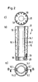
- FIG. 2 shows the details of the die.
- the die 6 is according to partial image a longitudinally split with two half-shells 6.1, 6.2.
- the Cross-sectional contour is essentially characterized by two each other opposite circular arc sections 14.1, 14.2, which then pass into the Fin section 15.1, 15.2.
- the closes Fins section 15.1, 15.2 straight from, but can also, for example, to the outside be a bit rounded.
- Partial image b shows a section B-B in partial image a.
- they are the two Half shells 6.1, 6.2 connecting expansion screws 16 to recognize that over the Length of the die 6 are distributed.
- the Die 6 At the upper open end, the Die 6 a funnel-shaped integrally formed portion 17, which then merges into the Cross-sectional contour shown in part a.
- a Bottom ring 18 At the lower open end is arranged, which is connected via expansion screws 19 with the die 6 is.
- Panel c shows the bottom of the die with the opening 20 for the arrangement of Auswerfers 11 (Figure 1d) and arranged distributed over the circumference Expansion screws 19.
- Figure 3 shows in the partial image a in a half-sided longitudinal section and in a half-sided View and a plan view of the pressed hole piece 8 and in the sub-picture b the finished fin cylinder 21.
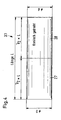
- FIG. 4 shows by way of example a mechanically processed block 3.1 before use in FIG the deep furnace 1 ( Figure 1a).
- a first section 27 of the block 3.1 becomes a machined cylindrical body with the diameter D mechanically.
- a second adjoining section 28 becomes a conical body with the Starting diameter D and the final diameter d machined.
- Both Diameter have a tolerance field from zero to plus x. For example, is the value x a millimeter.
- each section 27, 28 has the same Length, which corresponds to half the insert length L.
- the diameter difference between D and d is a few millimeters, preferably five millimeters.
- FIGS. 5 a and 5 b a section and a view show a pressed hole piece 30 shown with only one bulge 31. Also, this hole piece 30 has a pressed-on bottom 32, which is an integral part of the hole piece 30.
- the Arbor 31 may comparatively as shown in Figure 3b, channels 33 for the Hydraulic lines are arranged.
- the only one bulge 31 having Punch 30 is more difficult to manufacture than the previously described fin cylinder 21 (FIG. 3), since during the piercing process the mandrel 7 (FIGS. 1c, 1d) becomes lighter can run.
- Countermeasures can, for example, in the way that on the Bulge 31 opposite side more material 34 stops - as with the dashed lines in Figure 5b indicated - without directly a significant second To form bulge.
Landscapes
- Engineering & Computer Science (AREA)
- Mechanical Engineering (AREA)
- Forging (AREA)
- Pistons, Piston Rings, And Cylinders (AREA)
- Shaping Metal By Deep-Drawing, Or The Like (AREA)
Claims (10)
- Procédé destiné à la fabrication d'un cylindre, comportant au moins une voussure s'étendant vers l'extérieur et sur la longueur, et un fond en acier pour une unité à piston et cylindre, par extrusion au moyen d'un mandrin d'un bloc métallique porté à température de déformation, dans lequel un rondin ébouté ou un bloc de coulée continu rond est usiné mécaniquement à dimension avant le chauffage à la température de déformation comprise entre 1 250 °C et 1 310 °C, et l'ensemble de la surface de la pièce d'insert est décalaminé après le chauffage avec de l'eau sous pression, et le bloc métallique (3.1 à 3.3) ainsi préparé étant ensuite introduit dans une matrice (6) munie d'un espace creux complémentaire à la voussure, et perforé de façon fortement croissante en une phase de travail au moyen du mandrin (7) pour la réalisation d'une pièce perforée (8) avec un fond (10), un lubrifiant étant appliqué sur la matrice (6) et sur le mandrin (7) avant la perforation, la pièce perforée (8) pourvue d'un fond (10) étant ensuite retirée de la matrice (6), refroidie et décalaminée, et soumise finalement à un usinage mécanique de finition.
- Procédé selon la revendication 1,
caractérisé en ce qu'un premier tronçon (27) du bloc d'insert (3.1) est usiné mécaniquement en un corps cylindrique, et en ce qu'un deuxième tronçon (28) est usiné mécaniquement en un corps conique, le diamètre (d) du corps conique se réduisant étant orienté vers une face frontale d'extrémité. - Procédé selon la revendication 2,
caractérisé en ce que la longueur de chaque tronçon (27, 28) est identique, en ce que la longueur respective correspond à la moitié de la longueur (L) du bloc d'insert (3.1), et en ce que la tolérance diamétrale de chaque tronçon (27, 28) se situe dans la plage positive. - Procédé selon l'une quelconque des revendications 1 à 3,
caractérisé en ce que l'usinage mécanique du bloc d'insert (3.1) est un usinage au tour avec une rugosité Rz ≤ 80. - Procédé selon la revendication 1,
caractérisé en ce que, avant l'insertion du bloc chauffé, la position médiane du mandrin (7) est ajustée par rapport à la matrice (6). - Procédé selon l'une quelconque des revendications 1 à 5,
caractérisé en ce que, par rapport à la longueur de départ, le bloc chauffé (3.1 à 3.3) est perforé de façon croissante d'au moins 1,5 fois à 2,5 fois. - Procédé selon l'une quelconque des revendications 1 à 6,
caractérisé en ce que, après le retrait de la pièce perforée (8) de la matrice (6), le mandrin (7) et la matrice (6) sont fortement refroidis en retour. - Procédé selon la revendication 1,
caractérisé en ce que le lubrifiant est un mélange de verre pulvérisé et de graphite pur d'un rapport de 1/1 auquel est ajouté du verre soluble. - Procédé selon l'une quelconque des revendications 1 à 8,
caractérisé en ce que le bloc d'insert (3.1) usiné mécaniquement est inséré dans la matrice (6) avec le tronçon (28) de forme conique. - Procédé selon l'une quelconque des revendications 1 à 9,
caractérisé en ce que, après le retrait de la pièce perforée (8) de la matrice (6), et avant le décalaminage de la surface extérieure, la pièce perforée (8) est soumise à un traitement thermique.
Applications Claiming Priority (2)
| Application Number | Priority Date | Filing Date | Title |
|---|---|---|---|
| DE19845835 | 1998-09-28 | ||
| DE19845835A DE19845835C1 (de) | 1998-09-28 | 1998-09-28 | Verfahren zur Herstellung eines Zylinders mit einer Auswölbung |
Publications (2)
| Publication Number | Publication Date |
|---|---|
| EP0990769A1 EP0990769A1 (fr) | 2000-04-05 |
| EP0990769B1 true EP0990769B1 (fr) | 2004-11-10 |
Family
ID=7883476
Family Applications (1)
| Application Number | Title | Priority Date | Filing Date |
|---|---|---|---|
| EP99250342A Expired - Lifetime EP0990769B1 (fr) | 1998-09-28 | 1999-09-27 | Procédé de fabrication d'un cylindre comportant une extension longitudinale |
Country Status (4)
| Country | Link |
|---|---|
| US (1) | US6219914B1 (fr) |
| EP (1) | EP0990769B1 (fr) |
| AT (1) | ATE282137T1 (fr) |
| DE (2) | DE19845835C1 (fr) |
Cited By (1)
| Publication number | Priority date | Publication date | Assignee | Title |
|---|---|---|---|---|
| CN110465782A (zh) * | 2019-08-21 | 2019-11-19 | 中国第二重型机械集团德阳万航模锻有限责任公司 | 细长零件加工变形的控制方法 |
Families Citing this family (4)
| Publication number | Priority date | Publication date | Assignee | Title |
|---|---|---|---|---|
| CN104786022B (zh) * | 2015-04-13 | 2017-10-27 | 西北工业大学 | 一种大高径比斜l形环件的生产方法 |
| CN107234143B (zh) * | 2017-06-27 | 2019-03-01 | 中北大学 | 一种铝镁合金旋转挤压成形专用模具 |
| DE102020133024B3 (de) | 2020-12-10 | 2022-03-03 | Reika Gmbh & Co. Kg | Verfahren und Vorrichtung zur Entfernung der Schmierglasschicht von stranggepressten Metallrohren |
| CN115069810A (zh) * | 2022-07-20 | 2022-09-20 | 中北大学 | 带外纵筋筒形件的精确挤压成形模具及方法 |
Family Cites Families (10)
| Publication number | Priority date | Publication date | Assignee | Title |
|---|---|---|---|---|
| CH220539A (de) * | 1939-05-22 | 1942-04-15 | Waffen Und Munitionsfabrieken | Verfahren und Werkzeug zur Herstellung nahtloser Hohlkörper mit Längsrippen. |
| GB712352A (en) * | 1952-03-05 | 1954-07-21 | Heinz Beukenberg | Improved means for shifting conveyors in mining operations |
| US2908385A (en) * | 1958-03-05 | 1959-10-13 | Babcock & Wilcox Co | Method of lubricating a pierced extrusion billet |
| DE1929147A1 (de) * | 1969-06-09 | 1970-12-23 | Rheinstahl Siegener Eisenbahnb | Verfahren zur Herstellung von Zugtoepfen fuer Mittelpufferkupplungsfederpatronen |
| US3818733A (en) * | 1972-07-17 | 1974-06-25 | Babcock & Wilcox Co | Piercing process |
| DE2635342C2 (de) * | 1976-08-03 | 1981-09-24 | Mannesmann AG, 4000 Düsseldorf | Presse zum Warmlochen eines Metallblockes |
| GB2027619B (en) * | 1978-07-03 | 1982-05-19 | Lucas Industries Ltd | Making master cylinders |
| DE3432288A1 (de) * | 1984-09-01 | 1986-03-13 | Kocks Technik Gmbh & Co, 4010 Hilden | Verfahren und anlage zum herstellen nahtloser rohre |
| JP2676450B2 (ja) * | 1991-01-11 | 1997-11-17 | 株式会社荏原製作所 | 板金製ポンプケーシング |
| DE19649471A1 (de) * | 1996-11-29 | 1998-06-04 | Sempell Babcock Ag | Verfahren zur Herstellung des Armaturengehäuses eines Absperrschiebers |
-
1998
- 1998-09-28 DE DE19845835A patent/DE19845835C1/de not_active Expired - Fee Related
-
1999
- 1999-09-27 DE DE59911037T patent/DE59911037D1/de not_active Expired - Lifetime
- 1999-09-27 AT AT99250342T patent/ATE282137T1/de active
- 1999-09-27 EP EP99250342A patent/EP0990769B1/fr not_active Expired - Lifetime
- 1999-09-28 US US09/407,736 patent/US6219914B1/en not_active Expired - Lifetime
Cited By (2)
| Publication number | Priority date | Publication date | Assignee | Title |
|---|---|---|---|---|
| CN110465782A (zh) * | 2019-08-21 | 2019-11-19 | 中国第二重型机械集团德阳万航模锻有限责任公司 | 细长零件加工变形的控制方法 |
| CN110465782B (zh) * | 2019-08-21 | 2021-07-30 | 中国第二重型机械集团德阳万航模锻有限责任公司 | 细长零件加工变形的控制方法 |
Also Published As
| Publication number | Publication date |
|---|---|
| EP0990769A1 (fr) | 2000-04-05 |
| DE59911037D1 (de) | 2004-12-16 |
| ATE282137T1 (de) | 2004-11-15 |
| DE19845835C1 (de) | 2000-03-16 |
| US6219914B1 (en) | 2001-04-24 |
Similar Documents
| Publication | Publication Date | Title |
|---|---|---|
| WO2007025799A1 (fr) | Procede, ligne de fabrication et ebauche de piston destines a la fabrication d'un piston monopiece destine a des moteurs a combustion interne et piston destine a des moteurs a combustion interne | |
| DE102009048040A1 (de) | Verfahren und Vorrichtung zur spanlosen Herstellung eines Außengewindes auf hohlförmigen Werkstücken aus Metall | |
| WO2015039747A1 (fr) | Procédé permettant de produire une pièce frittée d'une hauteur de pièce moulée précise et ensemble de pièces composé de pièces frittées assemblées | |
| DE19622372B4 (de) | Verfahren und Vorrichtung zum Herstellen von Nockenwellen | |
| EP1108483A2 (fr) | Procédé et dispositif pour le fluotournage | |
| DE2630040A1 (de) | Verfahren und vorrichtung zum herstellen einer flachbettfelge | |
| EP0990769B1 (fr) | Procédé de fabrication d'un cylindre comportant une extension longitudinale | |
| DE3237692A1 (de) | Verfahren und vorrichtung zum schmieden eines rotationssymmetrischen metallteils, das mit wenigstens zwei flanschen und einer axialen ausnehmung versehen ist | |
| US2215943A (en) | Method for the production of hollow bodies closed at one side by punching of four-edged blocks | |
| EP2148752B1 (fr) | Procédé de fabrication d'élément de base d'arbre creux | |
| DE102005036419B4 (de) | Vorrichtung zur Herstellung ausgebauchter Hohlprofile, insbesondere von Gasgeneratorgehäusen für Airbageinrichtungen | |
| DE102010011711B4 (de) | Verfahren und Vorrichtung zur spanlosen Herstellung von Verbindungs-, Befestigungs- oder Verschlusselementen aus Metall mit Außengewinde | |
| EP0682999B1 (fr) | Article moulé, procédé et installation pour sa préparation | |
| DE4207964A1 (de) | Verfahren und vorrichtung zur herstellung von insbesondere als bits gestalteten schraubwerkzeugen in kreuzschlitzform oder dergleichen | |
| DE3144695A1 (de) | Verfahren zum walzen von hohlen gebilden | |
| EP1024913B1 (fr) | Procede et dispositif pour produire un arbre a partir d'un element tubulaire | |
| EP3863780B1 (fr) | Procédé et dispositif pour matricer des structures superficielles dans une face intérieure d'un tube ou d'une tige de soupape de moteur | |
| EP3585986B1 (fr) | Procédé de fabrication d'une soupape à refroidissement intérieur dotée d'une structure de refroidissement et soupape fabriquée au moyen dudit procédé | |
| DE3101123A1 (de) | Verfahren und einrichtung zum verformen eines metallstabes in ein tulpenfoermiges teil durch fliesspressen in einer geschlossenen kammer | |
| WO2010000233A1 (fr) | Procédé de production de matériau tubulaire | |
| DE2622138A1 (de) | Verfahren zur herstellung eines stranggepressten stahlteils zur verwendung in einer rollenkupplung | |
| DE2514434A1 (de) | Buchse, insbesondere aus verbundmaterial, wie gleitlagerbuchse, oder gehaeusebuchse sowie verfahren und werkzeug zu deren herstellung | |
| DE3448553C2 (de) | Blindbefestiger zum Festlegen einer Vielzahl von Werkstücken | |
| DE2107962A1 (de) | Verfahren und Vorrichtung zur Herstellung einer Hülse aus einem Rohling mittels Vorwärtsfließpressen | |
| WO2013152758A1 (fr) | Procédé et dispositif pour réaliser un filetage externe sans enlèvement de matière sur des pièces en métal |
Legal Events
| Date | Code | Title | Description |
|---|---|---|---|
| PUAI | Public reference made under article 153(3) epc to a published international application that has entered the european phase |
Free format text: ORIGINAL CODE: 0009012 |
|
| AK | Designated contracting states |
Kind code of ref document: A1 Designated state(s): AT BE CH CY DE DK ES FI FR GB GR IE IT LI LU MC NL PT SE |
|
| AX | Request for extension of the european patent |
Free format text: AL;LT;LV;MK;RO;SI |
|
| 17P | Request for examination filed |
Effective date: 20000315 |
|
| AKX | Designation fees paid |
Free format text: AT BE CH CY DE DK ES FI FR GB GR IE IT LI LU MC NL PT SE |
|
| 17Q | First examination report despatched |
Effective date: 20031029 |
|
| RAP1 | Party data changed (applicant data changed or rights of an application transferred) |
Owner name: V & M DEUTSCHLAND GMBH |
|
| GRAP | Despatch of communication of intention to grant a patent |
Free format text: ORIGINAL CODE: EPIDOSNIGR1 |
|
| GRAS | Grant fee paid |
Free format text: ORIGINAL CODE: EPIDOSNIGR3 |
|
| RBV | Designated contracting states (corrected) |
Designated state(s): AT DE FI GB SE |
|
| GRAA | (expected) grant |
Free format text: ORIGINAL CODE: 0009210 |
|
| AK | Designated contracting states |
Kind code of ref document: B1 Designated state(s): AT DE FI GB SE |
|
| REG | Reference to a national code |
Ref country code: GB Ref legal event code: FG4D Free format text: NOT ENGLISH |
|
| GBT | Gb: translation of ep patent filed (gb section 77(6)(a)/1977) |
Effective date: 20041110 |
|
| REG | Reference to a national code |
Ref country code: IE Ref legal event code: FG4D Free format text: GERMAN |
|
| REF | Corresponds to: |
Ref document number: 59911037 Country of ref document: DE Date of ref document: 20041216 Kind code of ref document: P |
|
| REG | Reference to a national code |
Ref country code: SE Ref legal event code: TRGR |
|
| REG | Reference to a national code |
Ref country code: IE Ref legal event code: FD4D |
|
| PLBE | No opposition filed within time limit |
Free format text: ORIGINAL CODE: 0009261 |
|
| STAA | Information on the status of an ep patent application or granted ep patent |
Free format text: STATUS: NO OPPOSITION FILED WITHIN TIME LIMIT |
|
| 26N | No opposition filed |
Effective date: 20050811 |
|
| PGFP | Annual fee paid to national office [announced via postgrant information from national office to epo] |
Ref country code: DE Payment date: 20180821 Year of fee payment: 20 |
|
| PGFP | Annual fee paid to national office [announced via postgrant information from national office to epo] |
Ref country code: SE Payment date: 20180824 Year of fee payment: 20 Ref country code: FI Payment date: 20180822 Year of fee payment: 20 Ref country code: GB Payment date: 20180823 Year of fee payment: 20 Ref country code: AT Payment date: 20180822 Year of fee payment: 20 |
|
| REG | Reference to a national code |
Ref country code: DE Ref legal event code: R071 Ref document number: 59911037 Country of ref document: DE |
|
| REG | Reference to a national code |
Ref country code: GB Ref legal event code: PE20 Expiry date: 20190926 |
|
| REG | Reference to a national code |
Ref country code: SE Ref legal event code: EUG |
|
| REG | Reference to a national code |
Ref country code: AT Ref legal event code: MK07 Ref document number: 282137 Country of ref document: AT Kind code of ref document: T Effective date: 20190927 |
|
| PG25 | Lapsed in a contracting state [announced via postgrant information from national office to epo] |
Ref country code: GB Free format text: LAPSE BECAUSE OF EXPIRATION OF PROTECTION Effective date: 20190926 |