EP0990769B1 - Method of making a cylinder having a longitudinal rib - Google Patents
Method of making a cylinder having a longitudinal rib Download PDFInfo
- Publication number
- EP0990769B1 EP0990769B1 EP99250342A EP99250342A EP0990769B1 EP 0990769 B1 EP0990769 B1 EP 0990769B1 EP 99250342 A EP99250342 A EP 99250342A EP 99250342 A EP99250342 A EP 99250342A EP 0990769 B1 EP0990769 B1 EP 0990769B1
- Authority
- EP
- European Patent Office
- Prior art keywords
- die
- block
- dome
- section
- machined
- Prior art date
- Legal status (The legal status is an assumption and is not a legal conclusion. Google has not performed a legal analysis and makes no representation as to the accuracy of the status listed.)
- Expired - Lifetime
Links
Images


Classifications
-
- B—PERFORMING OPERATIONS; TRANSPORTING
- B21—MECHANICAL METAL-WORKING WITHOUT ESSENTIALLY REMOVING MATERIAL; PUNCHING METAL
- B21C—MANUFACTURE OF METAL SHEETS, WIRE, RODS, TUBES OR PROFILES, OTHERWISE THAN BY ROLLING; AUXILIARY OPERATIONS USED IN CONNECTION WITH METAL-WORKING WITHOUT ESSENTIALLY REMOVING MATERIAL
- B21C23/00—Extruding metal; Impact extrusion
- B21C23/02—Making uncoated products
- B21C23/20—Making uncoated products by backward extrusion
- B21C23/205—Making products of generally elongated shape
-
- B—PERFORMING OPERATIONS; TRANSPORTING
- B23—MACHINE TOOLS; METAL-WORKING NOT OTHERWISE PROVIDED FOR
- B23P—METAL-WORKING NOT OTHERWISE PROVIDED FOR; COMBINED OPERATIONS; UNIVERSAL MACHINE TOOLS
- B23P15/00—Making specific metal objects by operations not covered by a single other subclass or a group in this subclass
-
- Y—GENERAL TAGGING OF NEW TECHNOLOGICAL DEVELOPMENTS; GENERAL TAGGING OF CROSS-SECTIONAL TECHNOLOGIES SPANNING OVER SEVERAL SECTIONS OF THE IPC; TECHNICAL SUBJECTS COVERED BY FORMER USPC CROSS-REFERENCE ART COLLECTIONS [XRACs] AND DIGESTS
- Y10—TECHNICAL SUBJECTS COVERED BY FORMER USPC
- Y10T—TECHNICAL SUBJECTS COVERED BY FORMER US CLASSIFICATION
- Y10T29/00—Metal working
- Y10T29/49—Method of mechanical manufacture
- Y10T29/49229—Prime mover or fluid pump making
- Y10T29/4927—Cylinder, cylinder head or engine valve sleeve making
- Y10T29/49272—Cylinder, cylinder head or engine valve sleeve making with liner, coating, or sleeve
-
- Y—GENERAL TAGGING OF NEW TECHNOLOGICAL DEVELOPMENTS; GENERAL TAGGING OF CROSS-SECTIONAL TECHNOLOGIES SPANNING OVER SEVERAL SECTIONS OF THE IPC; TECHNICAL SUBJECTS COVERED BY FORMER USPC CROSS-REFERENCE ART COLLECTIONS [XRACs] AND DIGESTS
- Y10—TECHNICAL SUBJECTS COVERED BY FORMER USPC
- Y10T—TECHNICAL SUBJECTS COVERED BY FORMER US CLASSIFICATION
- Y10T29/00—Metal working
- Y10T29/49—Method of mechanical manufacture
- Y10T29/4998—Combined manufacture including applying or shaping of fluent material
- Y10T29/49982—Coating
Definitions
- the invention relates to a method for producing a cylinder with at least an outward and over the length extending bulge and with a Steel floor for a piston-cylinder unit.
- This object is achieved according to the invention by a method for producing a Cylinder with at least one outward and over the length extending Bulge and with a steel floor for a piston-cylinder unit through Extruding a metal block heated to forming temperature over a dome, with a puffed round ingot or round cast block before heating up Forming temperature between 1250 ° C and 1310 ° C mechanically machined to measure and after heating, the entire surface of the insert with press water is descaled and then the prepared metal block in a with a with the Bulge provided complementary cavity provided matrix and by means of the Domes in one operation to form a hole piece with a bottom strong is punched ascending, wherein before punching on the female and the dome Lubricant is applied, then the bottomed hole piece ejected from the die, cooled and descaled and finally mechanically finished.
- a puffed round ingot or a Rundstranggußblock is mechanically machined to a temperature between 1250 and 1310 ° C before heating, preferably by turning with a roughness of R z ⁇ 80.
- the entire surface with press water at 300 ⁇ 10 5 Pa descaled and the block after use in die by means of a thorn perforated sharply rising.
- the block is lengthened by at least 1.5-fold to 2.5-fold, based on the initial length.
- the thorn does not pierce the block, but leaves a floor.
- a lubricant is applied to the matrix and the dome. This is preferably a mixed with water glass mixture of glass powder and pure graphite in the ratio 1: 1.
- the outer surface is descaled after cooling. Finally, a mechanical processing. Depending on the material and requirement, a heat treatment may be necessary, which takes place after the hole has been pushed out of the die and before descaling. Preferably, the heat treatment is a water treatment.
- the die is arranged vertically, but also a horizontal position is possible.
- the advantage of the strongly increasing punching is that the material also displaces radially is, so that the bulges forming the cavity of the die over a sufficient length to be fully filled.
- Condition is that the dome almost center-centric on the block is placed. Too large deviations lead to Committee, as the bulge is only partially filled.
- the exact center of the Dornes is determined in such a way that the dome in the cold state a piece in the Retracted die and radially the distance to the die is measured.
- radial displacement of the die is a precise Einjust réelle.
- For support a centering of the mandrel is a portion of the insert block to a cylindrical and the second section to a conical body mechanically machined, this section is inserted into the die.
- the Diameter tolerance of the two sections is in the plus range, so that a centering insertion of the block is ensured in the die.
- the die is longitudinally divided and has one of the form to be generated Cross-sectional contour on. In principle, you can also plan in one piece by planing the die produce. But that causes great difficulties and the finishing is problematic. It is simpler to produce a hollow block, this longitudinal and each half, preferably by milling mechanically edit. So that Machining tool has unrestricted spout, is made separately Bottom ring connected by means of expansion screws with the die.
- Figure 1a-e are in schematic form the invention essential Steps to make a cylinder with two opposite ones Bulges shown. These types of cylinders are also called a fin cylinder designated.
- Panel a shows a gas-heated deep furnace 1, on the bottom of the second according to this illustration, three to be heated and mechanical machined ( Figure 4) blocks 3.1, 3.2, 3.3 are placed.
- the gas heating of the Deep well 1 is symbolically characterized by flames 4.
- the above usually open part of the furnace 1 is heated by a sliding Cover 5 kept closed.
- Partial image b shows the high-pressure descaling of a block 3.1.
- This will be a flushing ring 12 is arranged centrally to the block 3.1 and the lateral surface of the block 3.1 under high pressure by means of circumferentially arranged nozzles 13th treated with water. The pressure is about 300 bar.
- the flushing ring 12 is doing moved up and down along the axis of the block 3.1. Not shown is the Descaling of the two top surfaces of the block 3.1.
- Panel c shows in longitudinal section the step of inserting the descaled Block 3.1 in the die 6 and the placement of the mandrel 7 on the upper deck surface of the block 3.1. It is easy to see that at this stage of the manufacturing process the fin sections 15.1, 15.2 of the die 6 are not yet filled.
- Partial d shows in longitudinal section the die 6, the dome 7 and the pressed hole piece 8.
- the plan view in the sub-picture e can be seen that by the strongly rising Punching the fins 9.1, 9.2 forming cavities are fully filled with material.
- the inserted block is not fully punched through, but it remains a floor 10th stand.
- An ejector 11 located at the bottom of the press pushes after pressing the hole piece 8 upwards, the slight taper of the die 6 supportive acts.
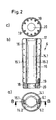
- FIG. 2 shows the details of the die.
- the die 6 is according to partial image a longitudinally split with two half-shells 6.1, 6.2.
- the Cross-sectional contour is essentially characterized by two each other opposite circular arc sections 14.1, 14.2, which then pass into the Fin section 15.1, 15.2.
- the closes Fins section 15.1, 15.2 straight from, but can also, for example, to the outside be a bit rounded.
- Partial image b shows a section B-B in partial image a.
- they are the two Half shells 6.1, 6.2 connecting expansion screws 16 to recognize that over the Length of the die 6 are distributed.
- the Die 6 At the upper open end, the Die 6 a funnel-shaped integrally formed portion 17, which then merges into the Cross-sectional contour shown in part a.
- a Bottom ring 18 At the lower open end is arranged, which is connected via expansion screws 19 with the die 6 is.
- Panel c shows the bottom of the die with the opening 20 for the arrangement of Auswerfers 11 (Figure 1d) and arranged distributed over the circumference Expansion screws 19.
- Figure 3 shows in the partial image a in a half-sided longitudinal section and in a half-sided View and a plan view of the pressed hole piece 8 and in the sub-picture b the finished fin cylinder 21.
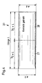
- FIG. 4 shows by way of example a mechanically processed block 3.1 before use in FIG the deep furnace 1 ( Figure 1a).
- a first section 27 of the block 3.1 becomes a machined cylindrical body with the diameter D mechanically.
- a second adjoining section 28 becomes a conical body with the Starting diameter D and the final diameter d machined.
- Both Diameter have a tolerance field from zero to plus x. For example, is the value x a millimeter.
- each section 27, 28 has the same Length, which corresponds to half the insert length L.
- the diameter difference between D and d is a few millimeters, preferably five millimeters.
- FIGS. 5 a and 5 b a section and a view show a pressed hole piece 30 shown with only one bulge 31. Also, this hole piece 30 has a pressed-on bottom 32, which is an integral part of the hole piece 30.
- the Arbor 31 may comparatively as shown in Figure 3b, channels 33 for the Hydraulic lines are arranged.
- the only one bulge 31 having Punch 30 is more difficult to manufacture than the previously described fin cylinder 21 (FIG. 3), since during the piercing process the mandrel 7 (FIGS. 1c, 1d) becomes lighter can run.
- Countermeasures can, for example, in the way that on the Bulge 31 opposite side more material 34 stops - as with the dashed lines in Figure 5b indicated - without directly a significant second To form bulge.
Abstract
Description
Die Erfindung betrifft ein Verfahren zur Herstellung eines Zylinders mit mindestens einer nach außen und über die Länge sich erstreckenden Auswölbung und mit einem Boden aus Stahl für eine Kolbenzylindereinheit.The invention relates to a method for producing a cylinder with at least an outward and over the length extending bulge and with a Steel floor for a piston-cylinder unit.
In modernen Bergwerken, insbesondere Kohlegruben wird in vollmechanisierten Betrieben mit einem selbsttätig schreitenden Ausbau gearbeitet. Der das Hangende abstützende Schreitausbau weist mindestens zwei, je nach Größe auch vier Hydraulikzylinder auf. In der Vergangenheit hat es bei der Anordnung der außenliegenden hydraulischen Leitungen an den Hydraulikzylindem Probleme gegeben, da bedingt durch den rauhen Betrieb immer wieder die außenliegenden Hydraulikleitungen beschädigt oder sogar zerstört worden sind. Aus diesem Grunde sind Zylinder mit Auswölbungen entwickelt worden, bei denen in der nach außen sich erstreckenden Auswölbung Hydraulikkanäle untergebracht sind, so daß diese vor dem herabstürzenden Gestein geschützt sind. Bei der bisher bekannten Herstellung solcher Zylinder wird von einem Schmiedestück ausgegangen, das allseitig mechanisch bearbeitet wird. Der Boden wird separat hergestellt und mit dem zylindrischen Teil verbunden. Dieses bekannte Verfahren ist hinsichtlich der Verbrauchsziffer und von der Taktzeit her als ungünstig anzusehen.In modern mines, especially coal mines will be in fully mechanized Operated with a self-advancing expansion. The hanging wall supporting walking extension has at least two, four depending on the size Hydraulic cylinder on. In the past, the arrangement of the external hydraulic lines to the Hydraulikzylindem problems Given, due to the rough operation always the outside Hydraulic lines have been damaged or even destroyed. For this reason Cylinders with bulges have been developed in which outward extending bulge hydraulic ducts are housed so that these before the falling rocks are protected. In the previously known production of such Cylinder is assumed to be a forging, mechanical on all sides is processed. The bottom is made separately and with the cylindrical part connected. This known method is in terms of consumption rate and of the tact time ago to be considered unfavorable.
Aus der DE-OS 1929147 ist ein Verfahren zur Herstellung von Zugtöpfen für
Mittelpufferkupplungsfederpatronen bekannt. Bei diesem Verfahren werden die
Zugtöpfe mit angepressten Ohren in einem Pressvorgang durch
Rückwärtshohlfließpresen erzeugt.
Beim Stauchen des Einsatzmaterials in Form eines Vierkant-Rund- oder
Rechteckblockes werden die Ohren mit verkürztem Abstand zum Fuss des Zugtopfes
in die Pressform eingedrückt, die beim Rückwärtshohlfließprozess aus der Pressform
in die Endlage steigen. Die Anzahl der Ohren ist durch entsprechende Gravur der
Pressbacken veränderbar.From DE-OS 1929147 a method for the production of Zugtöpfen for Mittelbufferkupplungsfederpatronen is known. In this method, the Zugtöpfe be generated with pressed ears in a pressing process by Rückwärtshohlfließpresen.
When upsetting the feed in the form of a square or rectangular block the ears are pressed with a shorter distance to the foot of the Zugtopfes in the mold, which rise in the Rückwärtshohlfließprozess from the die to the end position. The number of ears can be changed by appropriate engraving of the pressing jaws.
Es ist deshalb Aufgabe der Erfindung, ein Verfahren zur Herstellung eines Zylinders der gattungsmäßigen Art anzugeben, das sowohl hinsichtlich der Verbrauchsziffer, d. h. dem Verhältnis von Einsatzgewicht zu Fertiggewicht und von der Taktzeit her günstiger ist im Vergleich zu dem bekannten Herstellverfahren.It is therefore an object of the invention to provide a method for producing a cylinder of the generic type, both in terms of consumption, ie. H. the ratio of application weight to finished weight and the cycle time ago cheaper is compared to the known production method.
Gelöst wird diese Aufgabe erfindungsgemäß durch ein Verfahren zur Herstellung eines Zylinders mit mindestens einer nach außen und über die Länge sich erstreckenden Auswölbung und mit einem Boden aus Stahl für eine Kolbenzylindereinheit durch Fließpressen eines auf Umformtemperatur erwärmten Metallblocks über einen Dom, wobei ein geschopfter Rundingot oder ein Rundstranggußblock vor der Erwärmung auf Umformtemperatur zwischen 1250°C und 1310°C mechanisch auf Maß bearbeitet und nach der Erwärmung die gesamte Oberfläche des Einsatzstückes mit Preßwasser entzundert wird und danach der so vorbereitete Metallblock in eine mit einem mit der Auswölbung komplementären Hohlraum versehenen Matrize eingelegt und mittels des Domes in einem Arbeitsgang zur Bildung eines Lochstückes mit einem Boden stark steigend gelocht wird, wobei vor dem Lochen auf die Matrize und den Dom ein Schmiermittel aufgetragen wird, danach das mit einem Boden versehene Lochstück aus der Matrize ausgeschoben, abgekühlt und entzundert und abschließend mechanisch fertig bearbeitet wird.This object is achieved according to the invention by a method for producing a Cylinder with at least one outward and over the length extending Bulge and with a steel floor for a piston-cylinder unit through Extruding a metal block heated to forming temperature over a dome, with a puffed round ingot or round cast block before heating up Forming temperature between 1250 ° C and 1310 ° C mechanically machined to measure and after heating, the entire surface of the insert with press water is descaled and then the prepared metal block in a with a with the Bulge provided complementary cavity provided matrix and by means of the Domes in one operation to form a hole piece with a bottom strong is punched ascending, wherein before punching on the female and the dome Lubricant is applied, then the bottomed hole piece ejected from the die, cooled and descaled and finally mechanically finished.
Vorteilhafte Weiterbildungen des Verfahrens sind Bestandteil von Unteransprüchen.Advantageous developments of the method are part of subclaims.
Erfindungsgemäß wird ein geschopfter Rundingot oder ein Rundstranggußblock vor der Erwärmung auf eine Temperatur zwischen 1250 und 1310° C mechanisch auf Maß bearbeitet, vorzugsweise durch Drehen mit einer Rauheit von Rz ≤ 80. Nach der Erwärmung wird die gesamte Oberfläche mit Preßwasser bei 300 · 105 Pa entzundert und der Block nach Einsatz in Matrize mittels eines Dornes stark steigend gelocht. Dabei wird der Block bezogen auf die Ausgangslänge um mindestens das 1,5-fache bis 2,5-fache gelängt. Der Dorn locht den Block nicht durch, sondern beläßt einen Boden. Vor dem Lochen wird auf die Matrize und den Dom ein Schmiermittel aufgetragen. Dieses ist vorzugsweise ein mit Wasserglas versetztes Gemisch aus Glaspulver und Reingraphit im Verhältnis 1:1. Nach dem Ausschieben des Lochstückes aus der Matrize wird nach dem Abkühlen die äußere Oberfläche entzundert. Abschließend erfolgt eine mechanische Bearbeitung. Je nach Werkstoff und Anforderung kann eine Wärmebehandlung erforderlich sein, die nach dem Ausschieben des Lochstückes aus der Matrize und vor der Entzunderung erfolgt. Vorzugsweise ist die Wärmebehandlung eine Wasservergütung. Üblicherweise ist die Matrize vertikal angeordnet, aber auch eine horizontale Lage ist möglich.According to the invention, a puffed round ingot or a Rundstranggußblock is mechanically machined to a temperature between 1250 and 1310 ° C before heating, preferably by turning with a roughness of R z ≤ 80. After heating, the entire surface with press water at 300 · 10 5 Pa descaled and the block after use in die by means of a thorn perforated sharply rising. The block is lengthened by at least 1.5-fold to 2.5-fold, based on the initial length. The thorn does not pierce the block, but leaves a floor. Before punching, a lubricant is applied to the matrix and the dome. This is preferably a mixed with water glass mixture of glass powder and pure graphite in the ratio 1: 1. After pushing out the hole piece from the die, the outer surface is descaled after cooling. Finally, a mechanical processing. Depending on the material and requirement, a heat treatment may be necessary, which takes place after the hole has been pushed out of the die and before descaling. Preferably, the heat treatment is a water treatment. Usually, the die is arranged vertically, but also a horizontal position is possible.
Der Vorteil des stark steigenden Lochens ist, daß das Material auch radial verdrängt wird, so daß die die Auswölbung bildenden Hohlräume der Matrize über eine ausreichende Länge voll ausgefüllt werden. Bedingung dabei ist, daß der Dom nahezu mittenzentrisch auf dem Block aufgesetzt wird. Zu große Abweichungen führen zum Ausschuß, da die Auswölbung nur teilweise aufgefüllt wird. Die genaue Mittenlage des Dornes wird in der Weise ermittelt, daß der Dom im kalten Zustand ein Stück in die Matrize eingefahren und radial der Abstand zur Matrize vermessen wird. Durch radiales Verschieben der Matrize erfolgt eine genaue Einjustierung. Zur Unterstützung eines mittigen Aufsetzens des Dornes wird ein Abschnitt des Einsatzblockes zu einem zylindrischen und der zweite Abschnitt zu einem konischen Körper mechanisch bearbeitet, wobei dieser Abschnitt in die Matrize eingesetzt wird. Die Durchmessertoleranz der beiden Abschnitte liegt im Plusbereich, so daß ein zentrierendes Einsetzen des Blockes in die Matrize sichergestellt ist. The advantage of the strongly increasing punching is that the material also displaces radially is, so that the bulges forming the cavity of the die over a sufficient length to be fully filled. Condition is that the dome almost center-centric on the block is placed. Too large deviations lead to Committee, as the bulge is only partially filled. The exact center of the Dornes is determined in such a way that the dome in the cold state a piece in the Retracted die and radially the distance to the die is measured. By radial displacement of the die is a precise Einjustierung. For support a centering of the mandrel is a portion of the insert block to a cylindrical and the second section to a conical body mechanically machined, this section is inserted into the die. The Diameter tolerance of the two sections is in the plus range, so that a centering insertion of the block is ensured in the die.
Durch das steigende Lochen wird der Dom und die Matrize thermisch hoch belastet und es ist deshalb erforderlich, daß vor Einsatz des nächsten Blockes sowohl der Dom als auch die Matrize stark rückgekühlt werden. Aus maßlichen Gründen und im Hinblick auf eine Reduzierung des Umfanges der mechanischen Endbearbeitung liegt die Konizität der Matrize bei 0,75 %. Dies reicht gerade aus, damit das Lochstück mittels des Auswerfers aus der Matrize geschoben werden kann.Due to the increasing punching of the dome and the matrix is thermally highly loaded and it is therefore necessary that before using the next block both the Dom as well as the die are strongly recooled. For dimensional reasons and in the Regard to a reduction in the amount of mechanical finishing the conicity of the template at 0.75%. This is just enough for the hole piece can be pushed out of the die by means of the ejector.
Die Matrize ist längsgeteilt und weist eine der zu erzeugenden Form entsprechende Querschnittskontur auf. Im Prinzip kann man durch Hobeln die Matrize auch einstückig herstellen. Das bereitet aber große Schwierigkeiten und die Feinbearbeitung ist problematisch. Einfacher ist es, einen Hohlblock herzustellen, diesen längszuteilen und jede Hälfte, vorzugsweise durch Fräsen mechanisch zu bearbeiten. Damit das Bearbeitungswerkzeug ungehinderten Auslauf hat, wird der separat hergestellte Bodenring mittels Dehnschrauben mit der Matrize verbunden.The die is longitudinally divided and has one of the form to be generated Cross-sectional contour on. In principle, you can also plan in one piece by planing the die produce. But that causes great difficulties and the finishing is problematic. It is simpler to produce a hollow block, this longitudinal and each half, preferably by milling mechanically edit. So that Machining tool has unrestricted spout, is made separately Bottom ring connected by means of expansion screws with the die.
In der Zeichnung wird anhand eines Ausführungsbeispieles das erfindungsgemäße Verfahren näher erläutert. Es zeigen:
- Figur 1a-e
- die erfindungsgemäß wesentlichen Arbeitsschritte zur Herstellung eines Zylinders mit zwei einander gegenüberliegenden Auswölbungen
Figur 2- eine erfindungsgemäß ausgebildete Matrize
- Figur 3a
- ein gepreßtes Lochstück
- Figur 3b
- einen fertig bearbeiteten Zylinder
Figur 4- einen mechanisch bearbeiteten Einsatzblock
- Figur 5a
- ein gepreßtes Lochstück mit nur einer Auswölbung im Schnitt A-A in Figur 5b
- Figur 5b
- eine Ansicht in Richtung X in Figur 5a
- FIG. 1a-e
- the invention essential steps for producing a cylinder with two opposite bulges
- FIG. 2
- an inventively designed template
- FIG. 3a
- a pressed hole piece
- FIG. 3b
- a finished cylinder
- FIG. 4
- a machined insert block
- FIG. 5a
- a pressed hole piece with only one bulge in section AA in Figure 5b
- FIG. 5b
- a view in the direction X in Figure 5a
In Figur 1a-e sind in schematischer Form die erfindungsgemäß wesentlichen
Arbeitsschritte zur Herstellung eines Zylinders mit zwei einander gegenüberliegenden
Auswölbungen dargestellt. Diese Art von Zylinder werden auch als Flossenzylinder
bezeichnet. Teilbild a zeigt einen mit Gas beheizten Tiefofen 1, auf dessen Boden 2
entsprechend dieser Darstellung drei zu erwärmende geschopfte und mechanisch
bearbeitete (Figur 4) Blöcke 3.1, 3.2, 3.3 aufgestellt sind. Die Gasbeheizung des
Tiefofens 1 ist symbolisch durch Flammen 4 gekennzeichnet. Der oben normalerweise
offene Teil des Tiefofens 1 wird während der Erwärmung durch einen verschiebbaren
Deckel 5 verschlossen gehalten.In Figure 1a-e are in schematic form the invention essential
Steps to make a cylinder with two opposite ones
Bulges shown. These types of cylinders are also called a fin cylinder
designated. Panel a shows a gas-heated deep furnace 1, on the bottom of the second
according to this illustration, three to be heated and mechanical
machined (Figure 4) blocks 3.1, 3.2, 3.3 are placed. The gas heating of the
Deep well 1 is symbolically characterized by
Im Teilbild b ist die Hochdruckentzunderung eines Blockes 3.1 dargestellt. Dazu wird
ein Spülring 12 zentrisch zum Block 3.1 angeordnet und die Mantelfläche des Blockes
3.1 unter hohem Druck mittels der über in Umfangsrichtung angeordneten Düsen 13
mit Wasser beaufschlagt. Der Druck liegt bei ca. 300 bar. Der Spülring 12 wird dabei
entlang der Achse des Blockes 3.1 auf- und abbewegt. Nicht dargestellt ist die
Entzunderung der beiden Deckflächen des Blockes 3.1.Partial image b shows the high-pressure descaling of a block 3.1. This will be
a flushing
Teilbild c zeigt im Längsschnitt den Arbeitsschritt des Einsetzens des entzunderten
Blockes 3.1 in die Matrize 6 und das Aufsetzen des Dornes 7 auf die obere Deckfläche
des Blockes 3.1. Gut zu erkennen ist, daß in diesem Stadium des Herstellprozesses
die Flossenabschnitte 15.1, 15.2 der Matrize 6 noch nicht ausgefüllt sind.Panel c shows in longitudinal section the step of inserting the descaled
Block 3.1 in the
Teilbild d zeigt im Längsschnitt die Matrize 6, den Dom 7 und das gepreßte Lochstück
8. Der Draufsicht im Teilbild e ist zu entnehmen, daß durch das stark steigende
Lochen die die Flossen 9.1, 9.2 bildenden Hohlräume voll mit Material aufgefüllt sind.
Der eingesetzte Block wird nicht voll durchgelocht, sondern es bleibt ein Boden 10
stehen. Ein unten in der Presse angeordneter Auswerfer 11 schiebt nach dem Pressen
das Lochstück 8 nach oben, wobei die leichte Konizität der Matrize 6 unterstützend
wirkt.Partial d shows in longitudinal section the
Figur 2 zeigt die Einzelheiten der Matrize. Die Matrize 6 ist gemäß Teilbild a
längsgeteilt mit zwei Halbschalen 6.1, 6.2. Deutlich zu erkennen in dieser Darstellung
ist, daß die Innenfläche der beiden Halbschalen 6.1, 6.2 eine entsprechend dem
herzustellenden Flossenzylinder angepaßte Querschnittskontur aufweist. Die
Querschnittskontur ist im wesentlichen gekennzeichnet durch zwei einander
gegenüberliegende Kreisbogenabschnitte 14.1, 14.2, die dann übergehen in den
Flossenabschnitt 15.1, 15.2. In diesem Ausführungsbeispiel schließt der
Flossenabschnitt 15.1, 15.2 gerade ab, kann aber auch beispielsweise nach außen
etwas gerundet sein.Figure 2 shows the details of the die. The
Teilbild b zeigt einen Schnitt B-B im Teilbild a. In diesem Schnitt sind die die beiden
Halbschalen 6.1, 6.2 verbindenden Dehnschrauben 16 zu erkennen, die über die
Länge der Matrize 6 verteilt angeordnet sind. Am oberen offenen Ende weist die
Matrize 6 einen trichterförmig angeformten Abschnitt 17 auf, der dann übergeht in die
im Teilbild a dargestellte Querschnittskontur. Am unteren offenen Ende ist ein
Bodenring 18 angeordnet, der über Dehnschrauben 19 mit der Matrize 6 verbunden
ist.Partial image b shows a section B-B in partial image a. In this section, they are the two
Half shells 6.1, 6.2 connecting
Teilbild c zeigt die Unterseite der Matrize mit der Öffnung 20 für die Anordnung des
Auswerfers 11 (Figur 1d) und die über den Umfang verteilt angeordneten
Dehnschrauben 19.Panel c shows the bottom of the die with the
Figur 3 zeigt im Teilbild a in einem halbseitigen Längsschnitt und in einer halbseitigen
Ansicht sowie einer Draufsicht das gepreßte Lochstück 8 und im Teilbild b den
fertigbearbeiteten Flossenzylinder 21.Figure 3 shows in the partial image a in a half-sided longitudinal section and in a half-sided
View and a plan view of the pressed
Im direkten Vergleich zwischen dem Teilbild a und dem Teilbild b erkennt man, daß
der oberhalb der gestrichelten Linie 22 liegende Teil 23 des Lochstückes 8 abgetrennt
wird. Im unteren Drittel des zylindrischen Teiles wird rechts und links je ein Auge 24.1,
24.2 angeschweißt, damit der Flossenzylinder 21 schwenkbar in der hier nicht
dargestellten Kolbenzylindereinheit angeordnet werden kann. Der Boden 10 des
Lochstückes 8 wird mechanisch bearbeitet, so daß er eine den
Aufstellungsbedingungen angepaßte Kontur erhält. Die Innenfläche 25 des
Lochstückes 8 wird feingedreht und gehont, so daß in ihr der Kolben der
Kolbenzylindereinheit gleiten kann.In a direct comparison between the field a and the field b, it can be seen that
the lying above the dashed
In der Draufsicht sind im Teilbild b die hier in der obenliegenden Flosse 9.1
angeordneten Kanäle 26 dargestellt. Je nach Erfordernis können auch in der
gegenüberliegenden Flosse 9.2 Kanäle angeordnet werden. In the plan view are in the field b here in the overhead fin 9.1
arranged
Figur 4 zeigt beispielhaft einen mechanisch bearbeiteten Block 3.1 vor dem Einsatz in
den Tiefofen 1 (Figur 1a). Ein erster Abschnitt 27 des Blockes 3.1 wird zu einem
zylindrischen Körper mit dem Durchmesser D mechanisch bearbeitet. Ein zweiter
daran anschließender Abschnitt 28 wird zu einem konischen Körper mit dem
Ausgangsdurchmesser D und dem Enddurchmesser d mechanisch bearbeitet. Beide
Durchmesser weisen ein Toleranzfeld von Null bis plus x auf. Beispielsweise beträgt
der Wert x einen Millimeter. Vorzugsweise hat jeder Abschnitt 27, 28 die gleiche
Länge, wobei diese der halben Einsatzlänge L entspricht. Die Durchmesserdifferenz
zwischen D und d liegt bei einigen Millimetern, vorzugsweise bei fünf Millimetern.FIG. 4 shows by way of example a mechanically processed block 3.1 before use in FIG
the deep furnace 1 (Figure 1a). A
In Figur 5a und 5b ist in einem Schnitt und in einer Ansicht ein gepreßtes Lochstück 30
mit nur einer Auswölbung 31 dargestellt. Auch dieses Lochstück 30 weist einen
angepreßten Boden 32 auf, der integraler Bestandteil des Lochstückes 30 ist. In der
Auswölbung 31 können vergleichsweise wie in Figur 3b dargestellt, Kanäle 33 für die
Hydraulikleitungen angeordnet werden. Das nur eine Auswölbung 31 aufweisende
Lochstück 30 ist schwieriger herzustellen als der zuvor beschriebene Flossenzylinder
21 (Figur 3), da während des Lochprozesses der Dom 7 (Figur 1c, 1d) leichter
verlaufen kann. Gegensteuern kann man beispielsweise in der Art, daß auf der der
Auswölbung 31 gegenüberliegenden Seite mehr Material 34 stehen bleibt - wie mit den
gestrichelten Linien in Figur 5b angedeutet - ohne direkt eine signifikante zweite
Auswölbung zu bilden.In FIGS. 5 a and 5 b, a section and a view show a
Claims (10)
- Method of producing a cylinder with at least one rib protrusion that extends outwards and over the entire length and with a base made of steel for a piston cylinder unit, by extruding a metal block heated to forming temperature over a dome, whereby a cropped round ingot or a continuously cast round block is machined to size prior to the heating process to the forming temperature of between 1250 °C and 1310 °C, and after the heating process the entire surface of the piece is descaled with pressurised water, and after which the metal block (3.1 - 3.3) prepared in this way is placed into a die (6) which has a cavity that is complementary to the rib protrusion, and is stamped in a strongly increasing manner by means of the dome (7) in an operation to form a pierced blank (8) with a base (10), whereby a lubricant is applied, prior to the stamping process, to the die (6) and the dome (7), and after this the pierced blank (8) that has been provided with a base (10) is pushed out of the die (6), cooled and descaled, and is then finish-machined.
- Method as in Claim 1,
characterised in that
a first section (27) of the block (3.1) is machined to form a cylindrical body, and a second section (28) is machined to form a tapered body, the decreasing diameter (d) of the tapered section facing towards an end face. - Method as in Claim 1 and 2,
characterised in that
each section (27, 28) is of the same length, and the length in each case is equal to half the length (L) of the block (3.1), and the diameter tolerance for each section (27, 28) is in the positive range. - Method as in one of Claims 1 to 3,
characterised in that
the machining of the block (3.1) is a turning process with a surface roughness of Rz ≤ 80. - Method as in Claim 1,
characterised in that
the centre position of the dome (7) in relation to the die (6) is aligned before the heated block is inserted. - Method as in one of Claims 1 to 5,
characterised in that
the heated block (3.1 - 3.3) is stamped to increase by at least 1.5 times to 2.5 times in relation to its initial length. - Method as in one of Claims 1 to 6,
characterised in that,
after the removal of the pierced blank (8) from the die (6), the dome (7) and the die (6) are intensely re-cooled. - Method as in Claim 1,
characterised in that
the lubricant is a mixture of glass powder and pure graphite in the ratio of 1 : 1, mixed with water glass. - Method as in one of Claims 1 to 8,
characterised in that
the machined block (3.1) is inserted into the die (6) with the tapered section (28) first. - Method as in one of Claims 1 to 9,
characterised in that,
after the pierced blank (8) is pushed out of the die (6) and before the descaling of the outer surface, the blank (8) is subjected to a heat treatment.
Applications Claiming Priority (2)
| Application Number | Priority Date | Filing Date | Title |
|---|---|---|---|
| DE19845835A DE19845835C1 (en) | 1998-09-28 | 1998-09-28 | Production of a hollow cylinder with a bottom and at least one external protrusion extending over its entire length involves machining, heating and descaling of the blank before it is reverse-extruded by punch and die |
| DE19845835 | 1998-09-28 |
Publications (2)
| Publication Number | Publication Date |
|---|---|
| EP0990769A1 EP0990769A1 (en) | 2000-04-05 |
| EP0990769B1 true EP0990769B1 (en) | 2004-11-10 |
Family
ID=7883476
Family Applications (1)
| Application Number | Title | Priority Date | Filing Date |
|---|---|---|---|
| EP99250342A Expired - Lifetime EP0990769B1 (en) | 1998-09-28 | 1999-09-27 | Method of making a cylinder having a longitudinal rib |
Country Status (4)
| Country | Link |
|---|---|
| US (1) | US6219914B1 (en) |
| EP (1) | EP0990769B1 (en) |
| AT (1) | ATE282137T1 (en) |
| DE (2) | DE19845835C1 (en) |
Cited By (1)
| Publication number | Priority date | Publication date | Assignee | Title |
|---|---|---|---|---|
| CN110465782A (en) * | 2019-08-21 | 2019-11-19 | 中国第二重型机械集团德阳万航模锻有限责任公司 | The control method of thin and long units machining deformation |
Families Citing this family (4)
| Publication number | Priority date | Publication date | Assignee | Title |
|---|---|---|---|---|
| CN104786022B (en) * | 2015-04-13 | 2017-10-27 | 西北工业大学 | A kind of production method of the oblique L-shaped ring of larger ratio of height to diameter |
| CN107234143B (en) * | 2017-06-27 | 2019-03-01 | 中北大学 | A kind of almag rotary extrusion forming particular manufacturing craft |
| DE102020133024B3 (en) | 2020-12-10 | 2022-03-03 | Reika Gmbh & Co. Kg | Process and apparatus for removing the smear layer from extruded metal pipes |
| CN115069810A (en) * | 2022-07-20 | 2022-09-20 | 中北大学 | Precise extrusion forming die and method for cylindrical part with external longitudinal ribs |
Family Cites Families (10)
| Publication number | Priority date | Publication date | Assignee | Title |
|---|---|---|---|---|
| CH220539A (en) * | 1939-05-22 | 1942-04-15 | Waffen Und Munitionsfabrieken | Method and tool for the production of seamless hollow bodies with longitudinal ribs. |
| GB712352A (en) * | 1952-03-05 | 1954-07-21 | Heinz Beukenberg | Improved means for shifting conveyors in mining operations |
| US2908385A (en) * | 1958-03-05 | 1959-10-13 | Babcock & Wilcox Co | Method of lubricating a pierced extrusion billet |
| DE1929147A1 (en) * | 1969-06-09 | 1970-12-23 | Rheinstahl Siegener Eisenbahnb | Pressed casting for medium buffer spring - coupling cartridges |
| US3818733A (en) * | 1972-07-17 | 1974-06-25 | Babcock & Wilcox Co | Piercing process |
| DE2635342C2 (en) * | 1976-08-03 | 1981-09-24 | Mannesmann AG, 4000 Düsseldorf | Press for hot punching a metal block |
| GB2027619B (en) * | 1978-07-03 | 1982-05-19 | Lucas Industries Ltd | Making master cylinders |
| DE3432288A1 (en) * | 1984-09-01 | 1986-03-13 | Kocks Technik Gmbh & Co, 4010 Hilden | METHOD AND SYSTEM FOR PRODUCING SEAMLESS TUBES |
| JP2676450B2 (en) * | 1991-01-11 | 1997-11-17 | 株式会社荏原製作所 | Sheet metal pump casing |
| DE19649471A1 (en) * | 1996-11-29 | 1998-06-04 | Sempell Babcock Ag | Method for manufacturing the valve body of a gate valve |
-
1998
- 1998-09-28 DE DE19845835A patent/DE19845835C1/en not_active Expired - Fee Related
-
1999
- 1999-09-27 EP EP99250342A patent/EP0990769B1/en not_active Expired - Lifetime
- 1999-09-27 DE DE59911037T patent/DE59911037D1/en not_active Expired - Lifetime
- 1999-09-27 AT AT99250342T patent/ATE282137T1/en active
- 1999-09-28 US US09/407,736 patent/US6219914B1/en not_active Expired - Lifetime
Cited By (2)
| Publication number | Priority date | Publication date | Assignee | Title |
|---|---|---|---|---|
| CN110465782A (en) * | 2019-08-21 | 2019-11-19 | 中国第二重型机械集团德阳万航模锻有限责任公司 | The control method of thin and long units machining deformation |
| CN110465782B (en) * | 2019-08-21 | 2021-07-30 | 中国第二重型机械集团德阳万航模锻有限责任公司 | Method for controlling machining deformation of slender part |
Also Published As
| Publication number | Publication date |
|---|---|
| ATE282137T1 (en) | 2004-11-15 |
| DE19845835C1 (en) | 2000-03-16 |
| DE59911037D1 (en) | 2004-12-16 |
| US6219914B1 (en) | 2001-04-24 |
| EP0990769A1 (en) | 2000-04-05 |
Similar Documents
| Publication | Publication Date | Title |
|---|---|---|
| WO2007025799A1 (en) | Method, production line, and piston blank used for the production of a monolithic piston for combustion engines, and piston for combustion engines | |
| DE102009048040A1 (en) | Method and device for chipless production of an external thread on hollow metal workpieces | |
| DE19622372B4 (en) | Method and device for producing camshafts | |
| EP1108483A2 (en) | Method and device for flow-turning | |
| WO2015039747A1 (en) | Method for producing a sintered part having a highly precise molded part height and parts set of sintered joining parts | |
| DE3237692A1 (en) | METHOD AND DEVICE FOR FORGING A ROTATION-SYMMETRICAL METAL PART WITH AT LEAST TWO FLANGES AND AN AXIAL EXCEPTION | |
| DE2630040A1 (en) | METHOD AND DEVICE FOR MANUFACTURING A FLAT BED RIM | |
| EP0990769B1 (en) | Method of making a cylinder having a longitudinal rib | |
| US2215943A (en) | Method for the production of hollow bodies closed at one side by punching of four-edged blocks | |
| EP2148752B1 (en) | Method for producing hollow shaft base bodies | |
| DE102005036419B4 (en) | Device for producing bulged hollow profiles, in particular gas generator housings for airbag devices | |
| DE102010011711B4 (en) | Method and device for chipless production of connecting, fastening or closing elements of metal with external thread | |
| EP0682999B1 (en) | Article molded from metal powder and process and apparatus for preparing the same | |
| DE3144695A1 (en) | METHOD FOR ROLLING CAVES | |
| EP1024913B1 (en) | Method and device for producing a shaft from a tubular workpiece | |
| EP3863780B1 (en) | Method and device for embossing surface structures into an inside of a pipe or a valve shaft of a poppet valve | |
| EP3585986B1 (en) | Process for manufacturing an internally cooled valve having a cooling structure, and valve manufactured by said method | |
| DE3101123A1 (en) | METHOD AND DEVICE FOR DEFORMING A METAL BAR INTO A TULIP-SHAPED PART BY FLOW-PRESSING IN A CLOSED CHAMBER | |
| WO2010000233A1 (en) | Method for the production of pipe material | |
| DE2622138A1 (en) | METHOD OF MANUFACTURING AN EXTRUDED STEEL PART FOR USE IN A ROLLER CLUTCH | |
| DE2514434A1 (en) | Rolled bearing bush for shock absorber rods - has bore with divergent end portion | |
| DE2107962A1 (en) | Method and device for producing a sleeve from a blank by means of forward extrusion | |
| WO2013152758A1 (en) | Method and device for the non-machining production of an external thread on workpieces made of metal | |
| DE4235666A1 (en) | Method and device for producing a pipe end with a reduced diameter | |
| DE1302526C2 (en) | TOOL FOR EXTRUSION OF SOLID CAGES FOR SPHERICAL ROLLER BEARINGS |
Legal Events
| Date | Code | Title | Description |
|---|---|---|---|
| PUAI | Public reference made under article 153(3) epc to a published international application that has entered the european phase |
Free format text: ORIGINAL CODE: 0009012 |
|
| AK | Designated contracting states |
Kind code of ref document: A1 Designated state(s): AT BE CH CY DE DK ES FI FR GB GR IE IT LI LU MC NL PT SE |
|
| AX | Request for extension of the european patent |
Free format text: AL;LT;LV;MK;RO;SI |
|
| 17P | Request for examination filed |
Effective date: 20000315 |
|
| AKX | Designation fees paid |
Free format text: AT BE CH CY DE DK ES FI FR GB GR IE IT LI LU MC NL PT SE |
|
| 17Q | First examination report despatched |
Effective date: 20031029 |
|
| RAP1 | Party data changed (applicant data changed or rights of an application transferred) |
Owner name: V & M DEUTSCHLAND GMBH |
|
| GRAP | Despatch of communication of intention to grant a patent |
Free format text: ORIGINAL CODE: EPIDOSNIGR1 |
|
| GRAS | Grant fee paid |
Free format text: ORIGINAL CODE: EPIDOSNIGR3 |
|
| RBV | Designated contracting states (corrected) |
Designated state(s): AT DE FI GB SE |
|
| GRAA | (expected) grant |
Free format text: ORIGINAL CODE: 0009210 |
|
| AK | Designated contracting states |
Kind code of ref document: B1 Designated state(s): AT DE FI GB SE |
|
| REG | Reference to a national code |
Ref country code: GB Ref legal event code: FG4D Free format text: NOT ENGLISH |
|
| GBT | Gb: translation of ep patent filed (gb section 77(6)(a)/1977) |
Effective date: 20041110 |
|
| REG | Reference to a national code |
Ref country code: IE Ref legal event code: FG4D Free format text: GERMAN |
|
| REF | Corresponds to: |
Ref document number: 59911037 Country of ref document: DE Date of ref document: 20041216 Kind code of ref document: P |
|
| REG | Reference to a national code |
Ref country code: SE Ref legal event code: TRGR |
|
| REG | Reference to a national code |
Ref country code: IE Ref legal event code: FD4D |
|
| PLBE | No opposition filed within time limit |
Free format text: ORIGINAL CODE: 0009261 |
|
| STAA | Information on the status of an ep patent application or granted ep patent |
Free format text: STATUS: NO OPPOSITION FILED WITHIN TIME LIMIT |
|
| 26N | No opposition filed |
Effective date: 20050811 |
|
| PGFP | Annual fee paid to national office [announced via postgrant information from national office to epo] |
Ref country code: DE Payment date: 20180821 Year of fee payment: 20 |
|
| PGFP | Annual fee paid to national office [announced via postgrant information from national office to epo] |
Ref country code: SE Payment date: 20180824 Year of fee payment: 20 Ref country code: FI Payment date: 20180822 Year of fee payment: 20 Ref country code: GB Payment date: 20180823 Year of fee payment: 20 Ref country code: AT Payment date: 20180822 Year of fee payment: 20 |
|
| REG | Reference to a national code |
Ref country code: DE Ref legal event code: R071 Ref document number: 59911037 Country of ref document: DE |
|
| REG | Reference to a national code |
Ref country code: GB Ref legal event code: PE20 Expiry date: 20190926 |
|
| REG | Reference to a national code |
Ref country code: SE Ref legal event code: EUG |
|
| REG | Reference to a national code |
Ref country code: AT Ref legal event code: MK07 Ref document number: 282137 Country of ref document: AT Kind code of ref document: T Effective date: 20190927 |
|
| PG25 | Lapsed in a contracting state [announced via postgrant information from national office to epo] |
Ref country code: GB Free format text: LAPSE BECAUSE OF EXPIRATION OF PROTECTION Effective date: 20190926 |