EP0990384A1 - Verstelleinrichtung einer landwirtschaftlichen Erntemaschine - Google Patents
Verstelleinrichtung einer landwirtschaftlichen Erntemaschine Download PDFInfo
- Publication number
- EP0990384A1 EP0990384A1 EP99118282A EP99118282A EP0990384A1 EP 0990384 A1 EP0990384 A1 EP 0990384A1 EP 99118282 A EP99118282 A EP 99118282A EP 99118282 A EP99118282 A EP 99118282A EP 0990384 A1 EP0990384 A1 EP 0990384A1
- Authority
- EP
- European Patent Office
- Prior art keywords
- adjusting device
- cylinders
- piston
- plungers
- chamber pump
- Prior art date
- Legal status (The legal status is an assumption and is not a legal conclusion. Google has not performed a legal analysis and makes no representation as to the accuracy of the status listed.)
- Granted
Links
- 238000003306 harvesting Methods 0.000 title claims description 6
- 239000012530 fluid Substances 0.000 claims abstract description 12
- 230000000712 assembly Effects 0.000 claims description 11
- 238000000429 assembly Methods 0.000 claims description 11
- 230000006835 compression Effects 0.000 claims description 2
- 238000007906 compression Methods 0.000 claims description 2
- 238000009423 ventilation Methods 0.000 claims 1
- 239000000463 material Substances 0.000 abstract 1
- 241001124569 Lycaenidae Species 0.000 description 6
- 239000004459 forage Substances 0.000 description 6
- 240000008042 Zea mays Species 0.000 description 3
- 235000002017 Zea mays subsp mays Nutrition 0.000 description 3
- 239000010720 hydraulic oil Substances 0.000 description 3
- 235000016383 Zea mays subsp huehuetenangensis Nutrition 0.000 description 2
- 235000009973 maize Nutrition 0.000 description 2
- 244000025254 Cannabis sativa Species 0.000 description 1
- 235000005824 Zea mays ssp. parviglumis Nutrition 0.000 description 1
- 235000013339 cereals Nutrition 0.000 description 1
- 235000005822 corn Nutrition 0.000 description 1
- 238000006073 displacement reaction Methods 0.000 description 1
- 238000004146 energy storage Methods 0.000 description 1
- 238000000034 method Methods 0.000 description 1
- 230000001360 synchronised effect Effects 0.000 description 1
- 238000011144 upstream manufacturing Methods 0.000 description 1
- 238000013022 venting Methods 0.000 description 1
Images
Classifications
-
- A—HUMAN NECESSITIES
- A01—AGRICULTURE; FORESTRY; ANIMAL HUSBANDRY; HUNTING; TRAPPING; FISHING
- A01F—PROCESSING OF HARVESTED PRODUCE; HAY OR STRAW PRESSES; DEVICES FOR STORING AGRICULTURAL OR HORTICULTURAL PRODUCE
- A01F12/00—Parts or details of threshing apparatus
- A01F12/18—Threshing devices
- A01F12/28—Devices for adjusting the concaves
Definitions
- the invention relates to an adjusting device of an agricultural harvesting machine for machine parts and / or assemblies interacting within a conveyor line, of which at least one machine part or assembly is adjustable by means of springs Stops positioned to change the passage widths or openings for the crop is.
- the adjustment device in question is the for agricultural harvesters different designs are required, for example for forage harvesters, combine harvesters and the like.
- the mutually adjustable machine parts or assemblies can be of various types be designed. For example, it is necessary for forage harvesters when chopping Maize two so-called cracker rollers so that the corn kernels are broken down become. For combine harvesters, for example, it is necessary to adjust the concave.
- the machine parts or assemblies in question are normally within a conveyor line for the crop.
- the invention is based on the object of an adjustment device described in more detail at the beginning Kind in a constructively simple manner so that the setting is exact and can be carried out in the shortest possible time.
- the task is solved by the attacks by a fluid and in the Synchronous movable plungers are guided in cylinders, and that the control of the cylinders feedable fluid through a single fluidly connected to the cylinders with a multi-chamber pump equipped with a piston.
- the proposed solution eliminates the need for precise adjustment using the screws.
- the multi-chamber pump is designed so that all cylinders, depending on the type of adjustment same amount of fluid is supplied, or that the same amount of the cylinders in the Multi-chamber pump can flow. This will cause all plungers to be retracted or extended move by the same amount so that the machine parts are always set precisely or the assemblies is given. All that is now required is the multi-chamber pump to operate accordingly. This can then be installed at a suitable location, where it is easily accessible. This is usually the case with agricultural harvesters Driver's cabin. Hydraulic oil is preferably used as the fluid. This results in a simple one and particularly durable design.
- a structurally simple solution for the multi-chamber pump results if the number of Chambers coincides with the number of cylinders to be controlled, and that the piston so is stepped that when moving the piston always the same amount of Fluids out or flows out of the chambers.
- Such a solution is not only the exact one Setting the machine parts or assemblies given, but it will also be the number the components required for the adjustment are kept low.
- the piston of the multi-chamber pump is adjusted by hand. For example done via a threaded spindle. However, it is also possible that this with a Actuator is adjusted, for example, an electric motor drive, a controlled piston-cylinder unit or the like.
- the multi-chamber pump is expediently in the Driver's cab of the agricultural harvester installed and particularly advantageous It is provided with an indication of the size of the passage width or opening.
- the cylinders receiving the tappets can be assembled in different ways. For example possible that they are arranged on fixed components of the agricultural harvester are, and that the plunger directly on the adjustable machine parts or assemblies or act indirectly. In a reverse sense, it is also possible that the plunger receiving cylinders are arranged on the adjustable components, and that the plunger act on stationary components of the agricultural harvester. In particularly proven
- the adjustable components or assemblies are in the operating position Springs, tension springs, compression springs or compensating cylinders. Basically everyone can known energy storage can be used. The springs allow, for example, at avoid an increased throughput of crop, the machine part or the assembly can.
- the plunger not act directly on the machine part or on the assembly, but that they act on a two-armed lever act on the machine part to be adjusted at one end or the module is connected, and that at the other end or at the other end the spring or balance cylinder is connected.
- Such an arrangement is advantageous if, for example, a concave is to be adjusted.
- the tappets in closed cylinders are arranged and interact with adjusting pistons on which one end of a piston rod is attached, the other end of the machine part to be adjusted or on the assembly are articulated.
- the plunger arranged on both sides of the machine part or the assembly can be adjusted by an actuator. Because an agricultural harvester anyway is equipped with a hydraulic system, it is advantageous if the adjustment device is designed as a hydraulic adjustment unit. This adjustment unit is still with Fittings equipped for filling and venting.
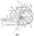
- FIG. 1 The arrangement shown in FIG. 1 is designed for a known forage harvester.
- Dash-dotted lines indicate the conveyor channel 1 forming the conveyor section.
- two cracker rollers 2, 3 partially protrude into it.
- These cracker rollers will be used when the forage harvester is used to harvest maize. Through the cracker rollers the grains are to be broken down, that is to say partially beaten.
- the Cracker rollers 2, 3 are driven in opposite directions in a manner not explained in detail.
- the in the Illustration of the left cracker roller 2 is mounted stationary, while the one on the right in the illustration Cracker roller 3 is mounted on both sides in rockers 4, which is about a horizontal axis 5 is pivotable.
- the housing block 28 removed with the cracker rollers 2, 3 and by a simple, the conveyor line closing housing replaced.
- Levers 6 are articulated to the side rockers 4.
- the adjustable cracker roller 3 is pulled in the direction of the cracker roller 2 by means of tension springs 7.
- the distance of the cracker roller 3 to the cracker roller 2 and thus also The passage width between these two rollers is determined by two lateral tappets 8, 9, form the stops for the rocker 4.
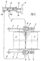
- the plungers 8, 9 are displaceable in cylinders 10, 11 arranged. These two cylinders 10, 11 are connected via two pressure lines 12, 13 a multi-chamber pump 14 fluidically connected. This is the multi-chamber pump 14 provided with two connections 14a and 14b.
- the multi-chamber pump 14 contains two chambers in this case with different diameters.
- the number of chambers of the multi-chamber pump depends on the number of connected cylinders 10, 11.
- the individual chambers are but continuously, since a piston 15 is moved in the multi-chamber pump 14, which accordingly the diameters of the chambers is stepped.
- the chambers and the piston 15 are designed so that when moving the piston 15 from both chambers the same amount of Fluid, preferably hydraulic oil, is pressed into the cylinders 10, 11 or during the process the piston 15 in the opposite direction the same amount of fluid into the chambers can flow in.
- the two plungers 8, 9 are always in synchronism, respectively move synchronously.
- the piston 15 is moved by hand since it is on a threaded spindle 16 is arranged, which can be rotated by means of a handwheel 17.
- a handwheel 17 serving as a display 18 rod, so that one by the position of the rod to an end face of the multi-chamber pump 14, the passage width can recognize between the two cracker rollers 2 and 3.
- the piston 15 also by an actuator, for example by an electric motor or adjusted by a piston-cylinder unit.
- the multi-chamber pump 14 is installed in the driver's cab of the agricultural harvester, so that the driver can adjust the cracker rollers 2, 3 from there can.
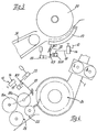
- Fig. 3 shows the adjustment of a concave 19 to a threshing drum 20.
- Das zu threshing crop is fed to the threshing device by means of an inclined conveyor 21.
- two-armed levers 22 are articulated on the concave 19 on both sides.
- At the free ends of the two two-armed levers 22 are energy stores in the form of Compensation cylinders 23 connected.
- On the free end areas of the two two-armed Lever 22 in turn act on the plungers 8, 9, which are in the same manner as in the embodiments 1 and 2 are arranged displaceably in the cylinders 10, 11.
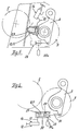
- a chopping device 24 is two pairs of pre-press rollers 25, 26 upstream.
- the upper rollers 25a and 26a are on both sides in two-armed levers 27 stored. These levers 27 are designed as angle levers.
- the energy accumulator in the form of the compensating cylinder 23 is connected in accordance with FIG. 3.
- the plunger 8 or 9 acts on the associated end of each lever 27 Chopping device 24 is connected to the conveyor channel 1, in which the aforementioned housing block 28 with the cracker rollers 2 and 3 and a post-accelerator, not shown are mounted.
- FIG. 5 essentially corresponds to the embodiment according to FIG. 1 and 2.
- the cylinders 10, 11 are on the pivotable rockers 4 firmly mounted so that the movable plunger 8, 9 on fixed parts of the machine frame support.
- the levers 6 and the tension springs 7 are through the two compensating cylinders 23 replaced with excluded pressure accumulator. This will achieved an inexpensive solution.
- the plungers 8, 9 are arranged on pistons 29, wherein the plunger 8, 9 to the rocker 4 show.
- the plungers 8, 9 contact another Piston 30, on each of which a piston rod 31 is attached.
- the piston rod 31 engages the associated side rocker 4.
- Each piston 29 and 30 and the respective plunger 8 or 9 are arranged in a common cylinder 32.
- On the side facing away from the rocker 4 Side is the connection for the pressure line 12 or 13 is provided.
- the invention is not restricted to the exemplary embodiments shown. It is essential that two or more adjustment units are adjusted by a single multi-chamber pump 14, in which plungers 8, 9 displaceable in a cylinder 10, 11 are moved. As a fluid hydraulic oil is preferred.
Landscapes
- Life Sciences & Earth Sciences (AREA)
- Environmental Sciences (AREA)
- Harvester Elements (AREA)
- Fluid-Pressure Circuits (AREA)
- Reciprocating Pumps (AREA)
- Lifting Devices For Agricultural Implements (AREA)
- Guiding Agricultural Machines (AREA)
Abstract
Description
- Figur 1
- die erfindungsgemäße Verstelleinrichtung in Verbindung mit einem Cräckerwalzenpaar eines Feldhäckslers in einer Seitenansicht,
- Figur 2
- eine der Fig. 1 entsprechende Draufsicht,
- Figur 3
- die erfindungsgemäße Verstelleinrichtung in Verbindung mit einem zu verstellenden Dreschkorb eines Mähdreschers,
- Figur 4
- die Verstelleinrichtung für ein Walzenpaar,
- Figur 5
- die Verstellung eines Cräckerwalzenpaares in einer gegenüber der Fig. 1 geänderten Ausführung und stärker schematisiert und
- Figur 6
- eine weitere Ausführungsform für die Einstellung eines Cräckerwalzenpaares entsprechend den Fig. 1 und 5.
- 1
- Förderkanal
- 2
- Cräckerwalze
- 3
- Cräckerwalze
- 4
- Schwingen
- 5
- horizontale Achse
- 6
- Hebel
- 7
- Zugfeder
- 8
- Stößel
- 9
- Stößel
- 10
- Zylinder
- 11
- Zylinder
- 12
- Druckleitung
- 13
- Druckleitung
- 14
- Mehrkammerpumpe
- 14a
- Anschluß
- 14b
- Anschluß
- 15
- Kolben
- 16
- Gewindespindel
- 17
- Handrad
- 18
- Anzeige
- 19
- Dreschkorb
- 20
- Dreschtrommel
- 21
- Schrägförderer
- 22
- Hebel
- 23
- Ausgleichszylinder
- 24
- Häckseleinrichtung
- 25
- Walzenpaar
- 25a
- Walze
- 26
- Walzenpaar
- 26a
- Walze
- 27
- Hebel
- 28
- Gehäuseblock
- 29
- Kolben
- 30
- Kolben
- 31
- Kolbenstange
- 32
- Zylinder
- 33
- Druckleitung
- 33a
- Druckspeicher
Claims (12)
- Verstelleinrichtung einer landwirtschaftlichen Erntemaschine für innerhalb einer Förderstrecke zusammenwirkenden Maschinenteilen und/oder Baugruppen, von denen wenigstens ein Maschinenteil bzw. eine Baugruppe mittels Federn durch verstellbare Anschläge zur Veränderung der Durchgangsweiten bzw. -öffnungen für das Erntegut positioniert ist,
dadurch gekennzeichnet, daß die Anschläge durch ein Fluid beaufschlagbare und im Gleichlauf bewegbare Stößel (8, 9) sind, und daß die Steuerung des den Zylindern (10, 11) zuführbaren Fluids durch eine einzige mit den Zylindern (10, 11) strömungsfähig verbundene, mit einem Kolben (15) ausgerüstete Mehrkammerpumpe (14) erfolgt. - Verstelleinrichtung nach Anspruch 1,
dadurch gekennzeichnet, daß die Anzahl der Kammern der Mehrkammerpumpe (14) mit der Anzahl der zu steuernden Zylinder (10, 11) übereinstimmt, und daß der Kolben (15) derart stufenförmig ausgebildet ist, daß beim Verfahren des Kolbens (15) stets die gleiche Menge des Fluids aus den Kammern aus- bzw. einströmt. - Verstelleinrichtung nach Anspruch 2,
dadurch gekennzeichnet, daß der Kolben (15) der Mehrkammerpumpe (14) von Hand oder durch einen Stelltrieb verstellbar ist. - Verstelleinrichtung nach Anspruch 3,
dadurch gekennzeichnet, daß der Stelltrieb ein elektromotorischer Antrieb, eine gesteuerte Kolbenzylindereinheit oder dergleichen ist. - Verstelleinrichtung nach einem oder mehreren der vorhergehenden Ansprüche 1 bis 4,
dadurch gekennzeichnet, daß die Mehrkammerpumpe (14) in der Fahrerkabine der landwirtschaftlichen Erntemaschine installiert ist und mit einer Anzeige (18) für die Größe der Durchgangsweite beziehungsweise -öffnung ausgerüstet ist. - Verstelleinrichtung nach einem oder mehreren der Ansprüche 1 bis 4,
dadurch gekennzeichnet, daß die Mehrkammerpumpe (14) an dem mit den Cräckerwalzen (2, 3) ausgerüsteten Gehäuseblock (28) installiert ist und mit diesem eine Baueinheit bildet. - Verstelleinrichtung nach einem oder mehreren der vorhergehenden Ansprüche 1 bis 6,
dadurch gekennzeichnet, daß die die Stößel (8, 9) aufnehmenden Zylinder (10, 11) an ortsfesten Bauteilen der landwirtschaftlichen Erntemaschine angeordnet sind, und daß die Stößel (8, 9) auf die verstellbaren Maschinenteile oder Baugruppen direkt oder indirekt einwirken. - Verstelleinrichtung nach einem oder mehreren der vorhergehenden Ansprüche 1 bis 6,
dadurch gekennzeichnet, daß die die Stößel (8, 9) aufnehmenden Zylinder (10, 11) an den verstellbaren Maschinenteilen (3) oder Baugruppen angeordnet sind, und daß die Stößel (8, 9) auf ortsfeste Bauteile der landwirtschaftlichen Erntemaschine einwirken. - Verstelleinrichtung nach einem oder mehreren der vorhergehenden Ansprüche 1 bis 8,
dadurch gekennzeichnet, daß die Federn Zugfedern (7), Druckfedern oder Ausgleichszylinder (23) sind. - Verstelleinrichtung nach einem oder mehreren der vorhergehenden Ansprüche 1 bis 9,
dadurch gekennzeichnet, daß die Stößel (8, 9) auf zweiarmige Hebel (22) wirken, daß an jedem Hebel (22) an einem Ende das zu verstellende Maschinenteil (19, 25, 26) oder die Baugruppe angeschlossen ist, und daß am anderen Ende jedes Hebels (22, 29) oder am anderen Endbereich Federn oder der Ausgleichszylinder (23) angeschlossen ist. - Verstelleinrichtung nach einem oder mehreren der vorhergehenden Ansprüche 1 bis 10,
dadurch gekennzeichnet, daß die Stößel (8, 9) in geschlossenen Zylindern angeordnet sind und mit Verstellkolben (30) zusammenwirken, an denen Kolbenstangen (31) befestigt sind, deren andere Enden an dem zu verstellenden Maschinenteil (3) oder an der Baugruppe angelenkt sind. - Verstelleinrichtung nach einem oder mehreren der vorhergehenden Ansprüche 1 bis 11,
dadurch gekennzeichnet, daß die Verstelleinrichtung als hydraulische Verstelleinheit ausgebildet ist und mit Befüllverschraubungen und Entlüftungsöffnungen versehen ist.
Applications Claiming Priority (2)
| Application Number | Priority Date | Filing Date | Title |
|---|---|---|---|
| DE19844894A DE19844894A1 (de) | 1998-09-30 | 1998-09-30 | Verstelleinrichtung einer landwirtschaftlichen Erntemaschine |
| DE19844894 | 1998-09-30 |
Publications (2)
| Publication Number | Publication Date |
|---|---|
| EP0990384A1 true EP0990384A1 (de) | 2000-04-05 |
| EP0990384B1 EP0990384B1 (de) | 2003-11-26 |
Family
ID=7882833
Family Applications (1)
| Application Number | Title | Priority Date | Filing Date |
|---|---|---|---|
| EP99118282A Expired - Lifetime EP0990384B1 (de) | 1998-09-30 | 1999-09-15 | Verstelleinrichtung einer landwirtschaftlichen Erntemaschine |
Country Status (4)
| Country | Link |
|---|---|
| US (1) | US6290599B1 (de) |
| EP (1) | EP0990384B1 (de) |
| AT (1) | ATE254832T1 (de) |
| DE (2) | DE19844894A1 (de) |
Cited By (1)
| Publication number | Priority date | Publication date | Assignee | Title |
|---|---|---|---|---|
| EP4635289A1 (de) | 2024-04-16 | 2025-10-22 | CLAAS Selbstfahrende Erntemaschinen GmbH | Selbstfahrender feldhäcksler |
Families Citing this family (17)
| Publication number | Priority date | Publication date | Assignee | Title |
|---|---|---|---|---|
| DE10021663A1 (de) * | 2000-05-04 | 2001-11-15 | Krone Bernhard Gmbh Maschf | Erntemaschine, insbesondere selbstfahrender Feldhäcksler |
| DE10030505A1 (de) * | 2000-06-21 | 2002-01-03 | Deere & Co | Vorrichtung zum Einstellen des Abstandes und/oder der Anpresskraft zweier Walzen einer Nachzerkleinerungseinrichtung |
| US6584755B2 (en) * | 2001-08-14 | 2003-07-01 | Deere & Company | Apparatus for adjusting the spacing and/or the contact pressure between two rollers of a kernel processor |
| DE10242579A1 (de) * | 2002-09-11 | 2005-03-17 | Claas Selbstfahrende Erntemaschinen Gmbh | Einrichtung zum Absorbieren von Schwingunggen in einer landwirtschaftlichen Erntemaschine |
| GB2414372A (en) | 2004-05-27 | 2005-11-30 | Cnh Belgium Nv | Kernel cracking assembly |
| DE102005055983A1 (de) * | 2005-11-24 | 2007-07-05 | Deere & Company, Moline | Zuführeinrichtung für einen Feldhäcksler |
| US7845362B2 (en) | 2007-02-27 | 2010-12-07 | Gm Global Technology Operations, Inc. | Washer fluid system for fuel cell vehicles |
| US7857690B2 (en) * | 2008-03-14 | 2010-12-28 | Deere & Company | Concave suspension control system and method for a threshing section in a harvesting machine |
| US8157629B2 (en) * | 2008-03-14 | 2012-04-17 | Deere & Company | Concave suspension for a threshing section in a harvesting machine |
| EP2123146B1 (de) * | 2008-05-20 | 2011-05-18 | CNH Belgium N.V. | Regelungssystem für Einzugswalzen eines Häckslers |
| US8133101B2 (en) * | 2009-12-18 | 2012-03-13 | Agco Corporation | Concave adjustment mechanism |
| US8133100B2 (en) * | 2009-12-18 | 2012-03-13 | Agco Corporation | Combine harvester processing system having adjustable concaves on a suspension system |
| DE102010016670A1 (de) * | 2010-04-28 | 2011-11-03 | Claas Selbstfahrende Erntemaschinen Gmbh | Drescheinrichtung für Mähdrescher |
| US9220200B2 (en) | 2011-11-29 | 2015-12-29 | Agco Corporation | Constant pressure concave assembly in a combine harvester processing system |
| DE102013004274B4 (de) * | 2013-03-13 | 2015-08-20 | Claas Saulgau Gmbh | Einzugvorrichtung für eine Häckseleinrichtung eines Feldhäckslers |
| US11147214B2 (en) * | 2019-06-26 | 2021-10-19 | Deere & Company | Combine with a pre-thresher |
| GB202210284D0 (en) * | 2022-07-13 | 2022-08-24 | Agco Int Gmbh | Agricultural baler |
Citations (4)
| Publication number | Priority date | Publication date | Assignee | Title |
|---|---|---|---|---|
| GB1301363A (de) * | 1970-04-09 | 1972-12-29 | ||
| DE2655119A1 (de) * | 1976-12-04 | 1978-06-08 | Fahr Ag Maschf | Verstelleinrichtung zur veraenderung der spaltbreite zwischen einer dreschtrommel und einem dreschkorb eines maehdreschers |
| DE9107689U1 (de) * | 1991-06-21 | 1991-09-19 | Claas Saulgau GmbH, 7968 Saulgau | Einzugsvorrichtung für Feldhäcksler |
| DE19538199A1 (de) * | 1995-10-13 | 1997-04-17 | Fortschritt Erntemaschinen | Feldhäcksler mit Konditioniereinrichtung |
Family Cites Families (7)
| Publication number | Priority date | Publication date | Assignee | Title |
|---|---|---|---|---|
| DE3114382C2 (de) * | 1981-04-09 | 1986-11-20 | Claas Ohg, 4834 Harsewinkel | Schüttlerloser selbstfahrender Mähdrescher |
| US4802496A (en) * | 1987-05-19 | 1989-02-07 | Deere & Company | Agricultural concave adjustment means |
| DD282836B5 (de) * | 1989-05-02 | 1994-03-31 | Fortschritt Erntemaschinen | Pressklappenverstellung fuer ballenpressen |
| DE4308084C2 (de) * | 1993-03-13 | 1998-06-04 | Claas Ohg | Hydraulisches Steuerventil |
| EP0631906B2 (de) * | 1993-06-28 | 2002-03-20 | New Holland Belgium N.V. | Verfahren zur Steuerung von selbstfahrenden landwirtschaftlichen Erntemaschinen |
| DE19520463A1 (de) * | 1995-06-03 | 1996-12-05 | Claas Ohg | Selbstfahrender Mähdrescher mit verstellbarem Dreschkorb |
| DE19640061C2 (de) * | 1996-09-28 | 2000-06-21 | Lely Welger Maschinenfabrik Gm | Ballenpresse mit einer Regeleinrichtung |
-
1998
- 1998-09-30 DE DE19844894A patent/DE19844894A1/de not_active Withdrawn
-
1999
- 1999-09-15 AT AT99118282T patent/ATE254832T1/de not_active IP Right Cessation
- 1999-09-15 DE DE59907842T patent/DE59907842D1/de not_active Expired - Lifetime
- 1999-09-15 EP EP99118282A patent/EP0990384B1/de not_active Expired - Lifetime
- 1999-09-30 US US09/409,516 patent/US6290599B1/en not_active Expired - Lifetime
Patent Citations (4)
| Publication number | Priority date | Publication date | Assignee | Title |
|---|---|---|---|---|
| GB1301363A (de) * | 1970-04-09 | 1972-12-29 | ||
| DE2655119A1 (de) * | 1976-12-04 | 1978-06-08 | Fahr Ag Maschf | Verstelleinrichtung zur veraenderung der spaltbreite zwischen einer dreschtrommel und einem dreschkorb eines maehdreschers |
| DE9107689U1 (de) * | 1991-06-21 | 1991-09-19 | Claas Saulgau GmbH, 7968 Saulgau | Einzugsvorrichtung für Feldhäcksler |
| DE19538199A1 (de) * | 1995-10-13 | 1997-04-17 | Fortschritt Erntemaschinen | Feldhäcksler mit Konditioniereinrichtung |
Cited By (1)
| Publication number | Priority date | Publication date | Assignee | Title |
|---|---|---|---|---|
| EP4635289A1 (de) | 2024-04-16 | 2025-10-22 | CLAAS Selbstfahrende Erntemaschinen GmbH | Selbstfahrender feldhäcksler |
Also Published As
| Publication number | Publication date |
|---|---|
| DE19844894A1 (de) | 2000-04-06 |
| US6290599B1 (en) | 2001-09-18 |
| ATE254832T1 (de) | 2003-12-15 |
| EP0990384B1 (de) | 2003-11-26 |
| DE59907842D1 (de) | 2004-01-08 |
Similar Documents
| Publication | Publication Date | Title |
|---|---|---|
| EP0990384B1 (de) | Verstelleinrichtung einer landwirtschaftlichen Erntemaschine | |
| DE19913710B4 (de) | Antriebsvorrichtung für ein Gleitstück einer Kniehebelpresse | |
| DE19925691B4 (de) | Landwirtschaftliche Erntemaschine | |
| EP0316923B1 (de) | Verteilereinrichtung für Häcksler | |
| EP0149787B2 (de) | Fördermengen-Regeleinrichtung für eine verstellbare Hydropumpe | |
| DD233920A5 (de) | Maehdrescher | |
| EP1027821B1 (de) | Hydraulische Stelleinrichtung | |
| EP0323833B1 (de) | Sieb- und Fördereinrichtung | |
| DE60225061T2 (de) | Fräsblechabstandsverstellung für doppelnadelbarrige raschelmaschinen | |
| EP0532853A1 (de) | Nahtschweissmaschine zum Verbinden von Blechzuschnitten | |
| DE102008025351A1 (de) | Umformmaschine | |
| EP0557866B1 (de) | Schere zum Trennen von Schrott | |
| DE2928950C2 (de) | Vorrichtung zum Entnehmen von Gärfutter aus Fahrsilos | |
| DE102011111251B4 (de) | Landmaschine | |
| DE2320218A1 (de) | Vorrichtung zum schneiden von bahnmaterial | |
| DE20211783U1 (de) | Pressstempelmechanismus einer Glasformmaschine | |
| DE3100093A1 (de) | Vorrichtung zur begrenzung des ausbauwiderstandes eines hydraulischen ausbauschildes | |
| EP1342402B1 (de) | Verfahren zur Verstellung von Führungsblechen und Häcksler zur Durchführung des Verfahrens | |
| DE10241106B4 (de) | Pressmaschine | |
| DE2645719C3 (de) | ||
| EP0216997B1 (de) | Drehpflug | |
| DE3329914A1 (de) | Schneidzylinder fuer eine erntemaschine | |
| DE3006866A1 (de) | Druckkompensationskolbenpumpe | |
| DE19621656C2 (de) | Mähdrescher mit einem aus zwei Schneidwerkshälften bestehenden Schneidwerk | |
| DE3731420C2 (de) | Selbstfahrende Erntemaschine |
Legal Events
| Date | Code | Title | Description |
|---|---|---|---|
| PUAI | Public reference made under article 153(3) epc to a published international application that has entered the european phase |
Free format text: ORIGINAL CODE: 0009012 |
|
| AK | Designated contracting states |
Kind code of ref document: A1 Designated state(s): AT BE CH CY DE DK ES FI FR GB GR IE IT LI LU MC NL PT SE |
|
| AX | Request for extension of the european patent |
Free format text: AL;LT;LV;MK;RO;SI |
|
| 17P | Request for examination filed |
Effective date: 20001005 |
|
| AKX | Designation fees paid |
Free format text: AT BE CH CY DE DK ES FI FR GB GR IE IT LI LU MC NL PT SE |
|
| 17Q | First examination report despatched |
Effective date: 20020823 |
|
| GRAH | Despatch of communication of intention to grant a patent |
Free format text: ORIGINAL CODE: EPIDOS IGRA |
|
| GRAS | Grant fee paid |
Free format text: ORIGINAL CODE: EPIDOSNIGR3 |
|
| GRAA | (expected) grant |
Free format text: ORIGINAL CODE: 0009210 |
|
| AK | Designated contracting states |
Kind code of ref document: B1 Designated state(s): AT BE CH CY DE DK ES FI FR GB GR IE IT LI LU MC NL PT SE |
|
| PG25 | Lapsed in a contracting state [announced via postgrant information from national office to epo] |
Ref country code: NL Free format text: LAPSE BECAUSE OF FAILURE TO SUBMIT A TRANSLATION OF THE DESCRIPTION OR TO PAY THE FEE WITHIN THE PRESCRIBED TIME-LIMIT Effective date: 20031126 Ref country code: IT Free format text: LAPSE BECAUSE OF FAILURE TO SUBMIT A TRANSLATION OF THE DESCRIPTION OR TO PAY THE FEE WITHIN THE PRESCRIBED TIME-LIMIT;WARNING: LAPSES OF ITALIAN PATENTS WITH EFFECTIVE DATE BEFORE 2007 MAY HAVE OCCURRED AT ANY TIME BEFORE 2007. THE CORRECT EFFECTIVE DATE MAY BE DIFFERENT FROM THE ONE RECORDED. Effective date: 20031126 Ref country code: IE Free format text: LAPSE BECAUSE OF FAILURE TO SUBMIT A TRANSLATION OF THE DESCRIPTION OR TO PAY THE FEE WITHIN THE PRESCRIBED TIME-LIMIT Effective date: 20031126 Ref country code: FI Free format text: LAPSE BECAUSE OF FAILURE TO SUBMIT A TRANSLATION OF THE DESCRIPTION OR TO PAY THE FEE WITHIN THE PRESCRIBED TIME-LIMIT Effective date: 20031126 Ref country code: CY Free format text: LAPSE BECAUSE OF FAILURE TO SUBMIT A TRANSLATION OF THE DESCRIPTION OR TO PAY THE FEE WITHIN THE PRESCRIBED TIME-LIMIT Effective date: 20031126 |
|
| REG | Reference to a national code |
Ref country code: GB Ref legal event code: FG4D Free format text: NOT ENGLISH |
|
| REG | Reference to a national code |
Ref country code: CH Ref legal event code: EP |
|
| REF | Corresponds to: |
Ref document number: 59907842 Country of ref document: DE Date of ref document: 20040108 Kind code of ref document: P |
|
| REG | Reference to a national code |
Ref country code: IE Ref legal event code: FG4D Free format text: GERMAN |
|
| PG25 | Lapsed in a contracting state [announced via postgrant information from national office to epo] |
Ref country code: SE Free format text: LAPSE BECAUSE OF FAILURE TO SUBMIT A TRANSLATION OF THE DESCRIPTION OR TO PAY THE FEE WITHIN THE PRESCRIBED TIME-LIMIT Effective date: 20040226 Ref country code: GR Free format text: LAPSE BECAUSE OF FAILURE TO SUBMIT A TRANSLATION OF THE DESCRIPTION OR TO PAY THE FEE WITHIN THE PRESCRIBED TIME-LIMIT Effective date: 20040226 Ref country code: DK Free format text: LAPSE BECAUSE OF FAILURE TO SUBMIT A TRANSLATION OF THE DESCRIPTION OR TO PAY THE FEE WITHIN THE PRESCRIBED TIME-LIMIT Effective date: 20040226 |
|
| PG25 | Lapsed in a contracting state [announced via postgrant information from national office to epo] |
Ref country code: ES Free format text: LAPSE BECAUSE OF FAILURE TO SUBMIT A TRANSLATION OF THE DESCRIPTION OR TO PAY THE FEE WITHIN THE PRESCRIBED TIME-LIMIT Effective date: 20040309 |
|
| GBT | Gb: translation of ep patent filed (gb section 77(6)(a)/1977) |
Effective date: 20040303 |
|
| NLV1 | Nl: lapsed or annulled due to failure to fulfill the requirements of art. 29p and 29m of the patents act | ||
| REG | Reference to a national code |
Ref country code: IE Ref legal event code: FD4D |
|
| ET | Fr: translation filed | ||
| PG25 | Lapsed in a contracting state [announced via postgrant information from national office to epo] |
Ref country code: LU Free format text: LAPSE BECAUSE OF NON-PAYMENT OF DUE FEES Effective date: 20040915 Ref country code: AT Free format text: LAPSE BECAUSE OF NON-PAYMENT OF DUE FEES Effective date: 20040915 |
|
| PG25 | Lapsed in a contracting state [announced via postgrant information from national office to epo] |
Ref country code: MC Free format text: LAPSE BECAUSE OF NON-PAYMENT OF DUE FEES Effective date: 20040930 Ref country code: LI Free format text: LAPSE BECAUSE OF NON-PAYMENT OF DUE FEES Effective date: 20040930 Ref country code: CH Free format text: LAPSE BECAUSE OF NON-PAYMENT OF DUE FEES Effective date: 20040930 |
|
| PLBE | No opposition filed within time limit |
Free format text: ORIGINAL CODE: 0009261 |
|
| STAA | Information on the status of an ep patent application or granted ep patent |
Free format text: STATUS: NO OPPOSITION FILED WITHIN TIME LIMIT |
|
| 26N | No opposition filed |
Effective date: 20040827 |
|
| REG | Reference to a national code |
Ref country code: CH Ref legal event code: PL |
|
| PG25 | Lapsed in a contracting state [announced via postgrant information from national office to epo] |
Ref country code: PT Free format text: LAPSE BECAUSE OF NON-PAYMENT OF DUE FEES Effective date: 20040426 |
|
| PGFP | Annual fee paid to national office [announced via postgrant information from national office to epo] |
Ref country code: GB Payment date: 20110923 Year of fee payment: 13 |
|
| GBPC | Gb: european patent ceased through non-payment of renewal fee |
Effective date: 20120915 |
|
| PG25 | Lapsed in a contracting state [announced via postgrant information from national office to epo] |
Ref country code: GB Free format text: LAPSE BECAUSE OF NON-PAYMENT OF DUE FEES Effective date: 20120915 |
|
| REG | Reference to a national code |
Ref country code: FR Ref legal event code: PLFP Year of fee payment: 17 |
|
| PGFP | Annual fee paid to national office [announced via postgrant information from national office to epo] |
Ref country code: FR Payment date: 20150923 Year of fee payment: 17 |
|
| REG | Reference to a national code |
Ref country code: DE Ref legal event code: R084 Ref document number: 59907842 Country of ref document: DE |
|
| PGFP | Annual fee paid to national office [announced via postgrant information from national office to epo] |
Ref country code: DE Payment date: 20160720 Year of fee payment: 18 |
|
| PGFP | Annual fee paid to national office [announced via postgrant information from national office to epo] |
Ref country code: BE Payment date: 20160922 Year of fee payment: 18 |
|
| REG | Reference to a national code |
Ref country code: FR Ref legal event code: ST Effective date: 20170531 |
|
| PG25 | Lapsed in a contracting state [announced via postgrant information from national office to epo] |
Ref country code: FR Free format text: LAPSE BECAUSE OF NON-PAYMENT OF DUE FEES Effective date: 20160930 |
|
| REG | Reference to a national code |
Ref country code: DE Ref legal event code: R119 Ref document number: 59907842 Country of ref document: DE |
|
| REG | Reference to a national code |
Ref country code: BE Ref legal event code: MM Effective date: 20170930 |
|
| PG25 | Lapsed in a contracting state [announced via postgrant information from national office to epo] |
Ref country code: DE Free format text: LAPSE BECAUSE OF NON-PAYMENT OF DUE FEES Effective date: 20180404 |
|
| PG25 | Lapsed in a contracting state [announced via postgrant information from national office to epo] |
Ref country code: BE Free format text: LAPSE BECAUSE OF NON-PAYMENT OF DUE FEES Effective date: 20170930 |