EP0989296A2 - Device for supplying fuel to a combustion engine - Google Patents
Device for supplying fuel to a combustion engine Download PDFInfo
- Publication number
- EP0989296A2 EP0989296A2 EP99116814A EP99116814A EP0989296A2 EP 0989296 A2 EP0989296 A2 EP 0989296A2 EP 99116814 A EP99116814 A EP 99116814A EP 99116814 A EP99116814 A EP 99116814A EP 0989296 A2 EP0989296 A2 EP 0989296A2
- Authority
- EP
- European Patent Office
- Prior art keywords
- fuel
- feed pump
- pump
- combustion engine
- feed
- Prior art date
- Legal status (The legal status is an assumption and is not a legal conclusion. Google has not performed a legal analysis and makes no representation as to the accuracy of the status listed.)
- Granted
Links
Images
Classifications
-
- F—MECHANICAL ENGINEERING; LIGHTING; HEATING; WEAPONS; BLASTING
- F02—COMBUSTION ENGINES; HOT-GAS OR COMBUSTION-PRODUCT ENGINE PLANTS
- F02M—SUPPLYING COMBUSTION ENGINES IN GENERAL WITH COMBUSTIBLE MIXTURES OR CONSTITUENTS THEREOF
- F02M37/00—Apparatus or systems for feeding liquid fuel from storage containers to carburettors or fuel-injection apparatus; Arrangements for purifying liquid fuel specially adapted for, or arranged on, internal-combustion engines
- F02M37/0047—Layout or arrangement of systems for feeding fuel
- F02M37/0052—Details on the fuel return circuit; Arrangement of pressure regulators
-
- F—MECHANICAL ENGINEERING; LIGHTING; HEATING; WEAPONS; BLASTING
- F02—COMBUSTION ENGINES; HOT-GAS OR COMBUSTION-PRODUCT ENGINE PLANTS
- F02M—SUPPLYING COMBUSTION ENGINES IN GENERAL WITH COMBUSTIBLE MIXTURES OR CONSTITUENTS THEREOF
- F02M69/00—Low-pressure fuel-injection apparatus ; Apparatus with both continuous and intermittent injection; Apparatus injecting different types of fuel
- F02M69/46—Details, component parts or accessories not provided for in, or of interest apart from, the apparatus covered by groups F02M69/02 - F02M69/44
- F02M69/54—Arrangement of fuel pressure regulators
Definitions
- the invention relates to a device for delivering fuel to one Internal combustion engine with the features mentioned in the preamble of the main claim.
- a generic device for is known from the document DE 195 13 822 A1 Conveying fuel from a fuel tank to an internal combustion engine Motor vehicle.
- the facility consists essentially of a Internal combustion powered feed pump, which is designed as a gear pump and is connected to the fuel tank via a delivery line. This Gear pump delivers the fuel to the injection system of the internal combustion engine.
- the feed pump forms a structural unit together with an air-conveying pump, whose suction side to generate a vacuum with a brake booster Motor vehicle is connected.
- the fuel supply is also previously known from document DE 196 12 605 A1 an internal combustion engine by means of a fuel-flushed and in the fuel tank to effect housed electric motor-driven feed pump.
- the feed pump is located in a storage pot also located in the fuel tank Active connection. There is a separate one in the lower area of this storage pot Liquid jet pump, via which the storage pot is filled and regulated becomes.
- a second additional pump is provided for the fuel supply described above Securing funding after the fuel tank runs empty is necessary, too deviates from the usual pump types in motor vehicle construction.
- the invention has for its object a generic pump with regard to improve their suction behavior after emptying the fuel tank while doing so to achieve self-venting.
- the object of the invention is achieved by the in the characterizing part of Features mentioned claims.
- the advantages of the invention are in the optimal constructive design of the pump unit with a pressure side Storage pot. Even after the fuel tank is empty, it is quick Fuel delivery with simultaneous ventilation, so a quick engine start is possible.
- the features of the subclaims are related to the description their effects explained.
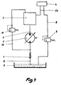
- FIG. 1 essential parts of the fuel supply of an internal combustion engine are shown schematically.
- a feed pump 1 driven by the internal combustion engine sucks fuel from a fuel tank 5 and initially fills a storage pot 3, which is also vented at the same time.
- a check valve 7 which opens in the direction of the fuel pump 1 and prevents the sucked-in fuel from falling back into the fuel tank 5.
- One or more fuel pressure lines 2a are connected to the storage pot 3 above the feed pump 1 (FIGS. 2 and 3), they feed an injection pump or pump-nozzle elements with fuel (neither of which is shown). The fuel that is not supplied to the internal combustion engine from the injection pump or the pump-nozzle elements flows back into the fuel tank 5 via a return line 8 and a pre-pressure valve 9.
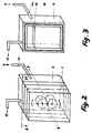
- the storage pot 3 axially covers the area of the feed pump 1 and part of the adjacent sealing limits (Fig. 2 and 3).
- the ones that form the sealing limits, for example seals 10 consisting of round rings are located in the area of the storage pot 3 in constant contact with fuel over a large part of its extent.
- A is preferably at the highest point of the storage pot 3 Pressure relief valve 11 connected. This pressure relief valve 11 opens at higher pressure than the pre-pressure valve 9. The return of fuel takes place via the Pressure relief valve 11 and a return line 12 to the suction side of the feed pump 1.
Abstract
Description
Die Erfindung betrifft eine Einrichtung zum Fördern von Kraftstoff zu einem Verbrennungsmotor mit den im Oberbegriff des Hauptanspruches genannten Merkmalen.The invention relates to a device for delivering fuel to one Internal combustion engine with the features mentioned in the preamble of the main claim.
Vorbekannt ist durch die Schrift DE 195 13 822 A1 einegattungsgemäße Einrichtung zum Fördern von Kraftstoff aus einem Kraftstofftank zu einem Verbrennungsmotor eines Kraftfahrzeuges. Die Einrichtung besteht im wesentlichen aus einer vom Verbrennungsmotor angetriebenen Förderpumpe, die als Zahnradpumpe ausgeführt ist und über eine Förderleitung mit dem Kraftstofftank in Verbindung steht. Diese Zahnradpumpe fördert den Kraftstoff zur Einspitzanlage des Verbrennungsmotors.A generic device for is known from the document DE 195 13 822 A1 Conveying fuel from a fuel tank to an internal combustion engine Motor vehicle. The facility consists essentially of a Internal combustion powered feed pump, which is designed as a gear pump and is connected to the fuel tank via a delivery line. This Gear pump delivers the fuel to the injection system of the internal combustion engine.
Die Förderpumpe bildet zusammen mit einer Luft fördernden Pumpe eine Baueinheit, deren Saugseite zur Erzeugung eines Unterdruckes mit einem Bremskraftverstärker des Kraftfahrzeuges verbunden ist.The feed pump forms a structural unit together with an air-conveying pump, whose suction side to generate a vacuum with a brake booster Motor vehicle is connected.
Bei leergefahrenem Kraftstofftank besteht bei dieser Bauart die Gefahr, daß der kraftstoffördernde Pumpenteil trocken steht. Diese Tatsache ist weder für den Ansaugvorgang noch für das Dichtsystem vorteilhaft.When the fuel tank is empty, there is a risk that the fuel-pump part is dry. This fact is not for the Intake process still advantageous for the sealing system.
Vorbekannt ist weiterhin durch die Schrift DE 196 12 605 A1, die Kraftstoffversorgung eines Verbrennungsmotors mittels einer von Kraftstoff umspülten und im Kraftstofftank untergebrachten elektromotorisch angetriebenen Förderpumpe zu bewirken. Die Förderpumpe steht mit einem ebenfalls im Kraftstofftank angeordneten Speichertopf in Wirkverbindung. Im unteren Bereich dieses Speichertopfes befindet sich eine gesonderte Flüssigkeitsstrahlpumpe, über welche die Füllung des Speichertopfes erfolgt und geregelt wird. Bei der vorbeschriebenen Kraftstoffversorgung ist eine zweite zusätzliche Pumpe zur Sicherung einer Förderung nach dem Leerfahren des Kraftstofftankes notwendig, die auch von den im Kraftfahrzeugbau üblichen Pumpenbauarten abweicht.The fuel supply is also previously known from document DE 196 12 605 A1 an internal combustion engine by means of a fuel-flushed and in the fuel tank to effect housed electric motor-driven feed pump. The The feed pump is located in a storage pot also located in the fuel tank Active connection. There is a separate one in the lower area of this storage pot Liquid jet pump, via which the storage pot is filled and regulated becomes. A second additional pump is provided for the fuel supply described above Securing funding after the fuel tank runs empty is necessary, too deviates from the usual pump types in motor vehicle construction.
Vorbekannt ist durch die Schrift DE 31 41 080 C2 eine ebenfalls nichtgattungsgemäße Pumpeinrichtung mit einer selbstansaugenden Kreiselpumpe. Die Saugleitung dieser Pumpe ist so ausgebildet, daß nach dem Abstellen der Pumpe in ihr eine bestimmte Flüssigkeitsmenge zurückbleibt. Beim ersten Anfahren saugt die Pumpe diese Flüssigkeitsmenge an, kann damit selbst ansaugen, sich nachfolgend für eine normale Förderung entlüften und füllen.Known from the document DE 31 41 080 C2 is also a non-generic one Pump device with a self-priming centrifugal pump. The suction line of this Pump is designed so that after switching off the pump in it a certain Amount of liquid remains. The pump sucks them the first time it starts up Amount of liquid, can suck itself in, subsequently for a normal Vent and fill the funding.
Der Erfindung liegt die Aufgabe zugrunde, eine gattungsgemäße Förderpumpe hinsichtlich ihres Saugverhaltens nach dem Leerfahren des Kraftstofftankes zu verbessern und dabei ein Selbstentlüften zu erreichen.The invention has for its object a generic pump with regard to improve their suction behavior after emptying the fuel tank while doing so to achieve self-venting.
Die erfindungsgemäße Lösung der Aufgabe erfolgt durch die im kennzeichnenden Teil der Patentansprüche genannten Merkmale. Die Vorzüge der Erfindung bestehen in der optimalen konstruktiven Gestaltung der Pumpeneinheit mit einem druckseitigen Speichertopf. Auch nach leergefahrenem Kraftstofftank erfolgt eine schnelle Kraftstofförderung bei gleichzeitiger Entlüftung, damit ist ein schneller Motorstart möglich. Die Merkmale der Unteransprüche werden in der Beschreibung im Zusammenhang mit ihren Wirkungen erläutert.The object of the invention is achieved by the in the characterizing part of Features mentioned claims. The advantages of the invention are in the optimal constructive design of the pump unit with a pressure side Storage pot. Even after the fuel tank is empty, it is quick Fuel delivery with simultaneous ventilation, so a quick engine start is possible. The features of the subclaims are related to the description their effects explained.
Anhand einer Zeichnung wird nachfolgend ein Ausführungsbeispiel der Erfindung beschrieben.An exemplary embodiment of the invention is described below with the aid of a drawing described.
Es zeigt:
- Fig. 1
- das Schema einer Kraftstoffversorgung eines Verbrennungsmotors,
- Fig. 2
- eine schematisch dargestellte Ausführungsform der Baueinheit Förderpumpe - Speichertopf,
- Fig. 3
- das Schema des Speichertopfes als Schnittdarstellung nach der Linie A-A in Fig. 2.
- Fig. 1
- the diagram of a fuel supply for an internal combustion engine,
- Fig. 2
- 1 shows a schematically illustrated embodiment of the feed pump-storage pot assembly,
- Fig. 3
- the diagram of the storage pot as a sectional view along the line AA in Fig. 2nd
In Fig. 1 sind wesentliche Teile der Kraftstoffversorgung eines Verbrennungsmotors
schematisch dargestellt. Eine vom Verbrennungsmotor angetriebene Förderpumpe 1
saugt aus einem Kraftstofftank 5 Kraftstoff an und füllt zunächst einen Speichertopf 3, der
sich dabei auch gleichzeitig entlüftet. In der Saugleitung 6 der Förderpumpe 1 befindet
sich ein in Richtung Kraftstoffpumpe 1 öffnendes Rückschlagventil 7, es verhindert das
Zurückfallen von angesaugtem Kraftstoff in den Kraftstofftank 5.
Eine oder mehrere Kraftstoffdruckleitungen 2a sind oberhalb der Förderpumpe 1 am
Speichertopf 3 angeschlossen (Fig. 2 und 3), sie speisen eine Einspritzpumpe oder
Pumpe-Düse-Elemente mit Kraftstoff (beides nicht dargestellt). Der nicht dem
Verbrennungsmotor von der Einspritzpumpe oder den Pumpe-Düse-Elementen
zugeführte Kraftstoff fließt über eine Rücklaufleitung 8 und ein Vordruckventil 9 in den
Kraftstofftank 5 zurück.In Fig. 1, essential parts of the fuel supply of an internal combustion engine are shown schematically. A
One or more
Der Speichertopf 3 überdeckt axial den Bereich der Förderpumpe 1 und einen Teil der
anliegenden Dichtgrenzen (Fig. 2 und 3). Die die Dichtgrenzen bildenden, beispielsweise
aus Rundringen bestehenden Dichtungen 10, stehen im Bereich des Speichertopfes 3
über einen großen Teil ihrer Erstreckung ständig mit Kraftstoff in Berührung.The
Vorzugsweise an der höchsten Stelle des Speichertopfes 3 ist ein
Druckbegrenzungsventil 11 angeschlossen. Dieses Druckbegrenzungsventil 11 öffnet bei
höherem Druck als das Vordruckventil 9. Der Rücklauf von Kraftstoff erfolgt über das
Druckbegrenzungsventil 11 und eine Rücklaufleitung 12 zur Saugseite der Förderpumpe
1.A is preferably at the highest point of the
Bei leergefahrenem Kraftstofftank 5 bleibt ein Mindestniveau 13 an Kraftstoff im
Speichertopf 3 (Fig. 3) erhalten. Bei abgestellter Förderpumpe 1 sorgt der Speichertopf 3
für eine Füllung ihrer Förderräume von der Druckseite her. Dabei kriecht Kraftstoff durch
die Spalten der Förderelemente und füllt ihre gesamten Förderräume.
Bei Wiederinbetriebnahme der Förderpumpe 1, die vorzugsweise als Zahnrad-,
Sperrflügel- oder Flügelzellenpumpe ausgeführt ist, erfolgt sofort, ohne Entlüften von
Außen, eine störungsfreie Kraftstofförderung zum Verbrennungsmotor, da die
Pumpenräume bereits gefüllt sind.When the
When the
Claims (5)
dadurch gekennzeichnet,
daß der Förderpumpe (1) druckseitig ein Speichertopf (3) nachgeschaltet ist, wobei eine Kraftstoffzulaufleitung (2a) bzw. Kraftstoffzulaufleitungen zur Einspritzanlage oberhalb der Förderpumpe (1) am Speichertopf (3) angeschlossen ist bzw. sind.Device for delivering fuel to an internal combustion engine with a feed pump for feeding an injection system, which is designed as a gear or vane pump that preferably delivers directly from the fuel tank and is driven by the internal combustion engine,
characterized,
that the feed pump (1) is connected on the pressure side to a reservoir (3), a fuel feed line (2a) or fuel feed lines to the injection system above the feed pump (1) being connected to the reservoir (3).
dadurch gekennzeichnet,
daß der Speichertopf (3) axial den Bereich der Förderpumpe (1) und einen Teil der anliegenden Dichtgrenzen überdeckt.Device according to claim 1,
characterized,
that the storage pot (3) axially covers the area of the feed pump (1) and part of the sealing limits.
dadurch gekennzeichnet,
daß ein Druckbegrenzungsventil (11) vorzugsweise an der höchsten Stelle des Speichertopfes (3) angeschlossen ist.Device according to claim 1,
characterized,
that a pressure relief valve (11) is preferably connected to the highest point of the storage pot (3).
dadurch gekennzeichnet,
daß das Druckbegrenzungsventil (11) über eine Kraftstoffrücklaufleitung (12) mit der Saugseite der Förderpumpe (1) verbunden ist.Device according to claim 3,
characterized,
that the pressure relief valve (11) is connected via a fuel return line (12) to the suction side of the feed pump (1).
dadurch gekennzeichnet,
daß in der Saugleitung (6) der Förderpumpe (1) ein den Rücklauf von angesaugtem Kraftstoff verhinderndes Rückschlagventil (7) angeordnet ist.Device according to claim 1,
characterized,
that in the suction line (6) of the feed pump (1) a check valve preventing the return of sucked fuel (7) is arranged.
Applications Claiming Priority (2)
| Application Number | Priority Date | Filing Date | Title |
|---|---|---|---|
| DE19843827A DE19843827A1 (en) | 1998-09-24 | 1998-09-24 | Device for delivering fuel to an internal combustion engine |
| DE19843827 | 1998-09-24 |
Publications (3)
| Publication Number | Publication Date |
|---|---|
| EP0989296A2 true EP0989296A2 (en) | 2000-03-29 |
| EP0989296A3 EP0989296A3 (en) | 2000-10-25 |
| EP0989296B1 EP0989296B1 (en) | 2003-08-20 |
Family
ID=7882106
Family Applications (1)
| Application Number | Title | Priority Date | Filing Date |
|---|---|---|---|
| EP99116814A Expired - Lifetime EP0989296B1 (en) | 1998-09-24 | 1999-09-01 | Device for supplying fuel to a combustion engine |
Country Status (4)
| Country | Link |
|---|---|
| EP (1) | EP0989296B1 (en) |
| AT (1) | ATE247774T1 (en) |
| DE (2) | DE19843827A1 (en) |
| ES (1) | ES2207095T3 (en) |
Families Citing this family (1)
| Publication number | Priority date | Publication date | Assignee | Title |
|---|---|---|---|---|
| DE10026373A1 (en) * | 2000-05-27 | 2001-11-29 | Volkswagen Ag | High pressure fuel injection system for diesel motors forms a fuel reserve at the flow vessel in the supply circuit to be extracted by the high pressure pump for a constant fuel injection pressure at all motor speeds |
Citations (2)
| Publication number | Priority date | Publication date | Assignee | Title |
|---|---|---|---|---|
| GB2023716A (en) * | 1978-05-31 | 1980-01-03 | Bosch Gmbh Robert | Fuel feed unit |
| US5456233A (en) * | 1993-04-28 | 1995-10-10 | Robert Bosch Gmbh | Fuel injection arrangement for internal combustion engines |
Family Cites Families (7)
| Publication number | Priority date | Publication date | Assignee | Title |
|---|---|---|---|---|
| GB1474565A (en) * | 1974-11-05 | 1977-05-25 | Gen Motors France | Internal combustion engine fuel pumps |
| DE3141080C2 (en) * | 1981-10-16 | 1984-04-12 | Mtu Motoren- Und Turbinen-Union Friedrichshafen Gmbh, 7990 Friedrichshafen | "Self-priming centrifugal pump" |
| DE3509374A1 (en) * | 1985-03-15 | 1986-09-25 | Robert Bosch Gmbh, 7000 Stuttgart | DEVICE FOR PROMOTING FUEL FROM A STORAGE TANK TO THE INTERNAL COMBUSTION ENGINE OF A MOTOR VEHICLE |
| DE3903313A1 (en) * | 1989-02-04 | 1990-08-09 | Bosch Gmbh Robert | STORAGE FUEL INJECTION DEVICE |
| US5363827A (en) * | 1993-10-14 | 1994-11-15 | Carter Automotive Company, Inc. | Fuel pump assembly |
| DE19549507C2 (en) * | 1995-04-12 | 2002-06-06 | Bosch Gmbh Robert | Device for delivering fuel from a storage tank to an internal combustion engine of a motor vehicle |
| DE19612605A1 (en) * | 1996-03-29 | 1997-10-02 | Bosch Gmbh Robert | Device for blocking return of fuel into storage vessel surrounding pump |
-
1998
- 1998-09-24 DE DE19843827A patent/DE19843827A1/en not_active Withdrawn
-
1999
- 1999-09-01 AT AT99116814T patent/ATE247774T1/en not_active IP Right Cessation
- 1999-09-01 EP EP99116814A patent/EP0989296B1/en not_active Expired - Lifetime
- 1999-09-01 ES ES99116814T patent/ES2207095T3/en not_active Expired - Lifetime
- 1999-09-01 DE DE59906653T patent/DE59906653D1/en not_active Expired - Lifetime
Patent Citations (2)
| Publication number | Priority date | Publication date | Assignee | Title |
|---|---|---|---|---|
| GB2023716A (en) * | 1978-05-31 | 1980-01-03 | Bosch Gmbh Robert | Fuel feed unit |
| US5456233A (en) * | 1993-04-28 | 1995-10-10 | Robert Bosch Gmbh | Fuel injection arrangement for internal combustion engines |
Also Published As
| Publication number | Publication date |
|---|---|
| ATE247774T1 (en) | 2003-09-15 |
| ES2207095T3 (en) | 2004-05-16 |
| DE19843827A1 (en) | 2000-03-30 |
| EP0989296A3 (en) | 2000-10-25 |
| DE59906653D1 (en) | 2003-09-25 |
| EP0989296B1 (en) | 2003-08-20 |
Similar Documents
| Publication | Publication Date | Title |
|---|---|---|
| EP1336043B1 (en) | Fuel injection system for internal combustion engines exhibiting improved start behavior | |
| DE102010053387B4 (en) | filter device | |
| EP1296060B1 (en) | Fuel injection system for an internal combustion engine | |
| WO2000077389A1 (en) | Pump assembly for supplying fuel | |
| DE10134572A1 (en) | Vehicle fuel supply system, comprises tank of fuel which also contains piston driven by compressed gas and sealed by bellows | |
| DE3235413A1 (en) | FUEL INJECTION DEVICE | |
| DE10136399A1 (en) | Fuel jet pump for motor vehicles | |
| EP1254311B1 (en) | Fuel supply system for internal combustion engines allowing for an improved filling of the fuel line | |
| DE102017203609A1 (en) | Device for injecting water into an internal combustion engine | |
| DE2705721A1 (en) | HYDRAULIC CIRCUIT WITH A MAIN AND CHARGE PUMP | |
| WO2010012525A1 (en) | Fuel feeding device for an internal combustion engine | |
| WO2003052262A1 (en) | Low-pressure circuit for a reservoir injection system | |
| EP0989296B1 (en) | Device for supplying fuel to a combustion engine | |
| DE102007033419A1 (en) | Dry sump lubricating device for internal combustion engine, has suction pump for extracting lubricant from internal combustion engine to lubricant tank | |
| DE19501353C2 (en) | Fuel delivery device for an internal combustion engine | |
| DE10059423A1 (en) | Device for conveying liquids, in particular fuel | |
| DE3514196A1 (en) | FUEL SUPPLY SYSTEM FOR INTERNAL COMBUSTION ENGINES WITH FUEL INJECTION | |
| DE19719607A1 (en) | Device for supplying fuel to an internal combustion engine | |
| WO2004027250A1 (en) | Fuel injection unit for internal combustion engines | |
| DE2500957A1 (en) | ROTARY PISTON COMBUSTION MACHINE IN TROCHOID DESIGN | |
| EP0479081A1 (en) | Pressure supply system for a vehicle transmission | |
| EP0162833B1 (en) | Piston compressor | |
| EP1275843A2 (en) | Internal combustion engine for motor vehicle | |
| DE4106697C1 (en) | Fuel additive dosing device - is used in vehicle and incorporates cylinder divided into two working chambers by piston | |
| DD130166B1 (en) | FUEL SYSTEM FOR AIR COMPRESSED INTERNAL COMBUSTION ENGINES! |
Legal Events
| Date | Code | Title | Description |
|---|---|---|---|
| PUAI | Public reference made under article 153(3) epc to a published international application that has entered the european phase |
Free format text: ORIGINAL CODE: 0009012 |
|
| AK | Designated contracting states |
Kind code of ref document: A2 Designated state(s): AT BE CH CY DE DK ES FI FR GB GR IE IT LI LU MC NL PT SE |
|
| AX | Request for extension of the european patent |
Free format text: AL;LT;LV;MK;RO;SI |
|
| PUAL | Search report despatched |
Free format text: ORIGINAL CODE: 0009013 |
|
| AK | Designated contracting states |
Kind code of ref document: A3 Designated state(s): AT BE CH CY DE DK ES FI FR GB GR IE IT LI LU MC NL PT SE |
|
| AX | Request for extension of the european patent |
Free format text: AL;LT;LV;MK;RO;SI |
|
| 17P | Request for examination filed |
Effective date: 20010425 |
|
| AKX | Designation fees paid |
Free format text: AT BE CH CY DE DK ES FI FR GB GR IE IT LI LU MC NL PT SE |
|
| 17Q | First examination report despatched |
Effective date: 20020614 |
|
| GRAH | Despatch of communication of intention to grant a patent |
Free format text: ORIGINAL CODE: EPIDOS IGRA |
|
| GRAH | Despatch of communication of intention to grant a patent |
Free format text: ORIGINAL CODE: EPIDOS IGRA |
|
| GRAA | (expected) grant |
Free format text: ORIGINAL CODE: 0009210 |
|
| AK | Designated contracting states |
Designated state(s): AT BE CH CY DE DK ES FI FR GB GR IE IT LI LU MC NL PT SE |
|
| PG25 | Lapsed in a contracting state [announced via postgrant information from national office to epo] |
Ref country code: NL Free format text: LAPSE BECAUSE OF FAILURE TO SUBMIT A TRANSLATION OF THE DESCRIPTION OR TO PAY THE FEE WITHIN THE PRESCRIBED TIME-LIMIT Effective date: 20030820 Ref country code: IE Free format text: LAPSE BECAUSE OF FAILURE TO SUBMIT A TRANSLATION OF THE DESCRIPTION OR TO PAY THE FEE WITHIN THE PRESCRIBED TIME-LIMIT Effective date: 20030820 Ref country code: FI Free format text: LAPSE BECAUSE OF FAILURE TO SUBMIT A TRANSLATION OF THE DESCRIPTION OR TO PAY THE FEE WITHIN THE PRESCRIBED TIME-LIMIT Effective date: 20030820 |
|
| REG | Reference to a national code |
Ref country code: GB Ref legal event code: FG4D Free format text: NOT ENGLISH |
|
| REG | Reference to a national code |
Ref country code: CH Ref legal event code: EP |
|
| PG25 | Lapsed in a contracting state [announced via postgrant information from national office to epo] |
Ref country code: LU Free format text: LAPSE BECAUSE OF NON-PAYMENT OF DUE FEES Effective date: 20030901 Ref country code: CY Free format text: LAPSE BECAUSE OF FAILURE TO SUBMIT A TRANSLATION OF THE DESCRIPTION OR TO PAY THE FEE WITHIN THE PRESCRIBED TIME-LIMIT Effective date: 20030901 Ref country code: AT Free format text: LAPSE BECAUSE OF NON-PAYMENT OF DUE FEES Effective date: 20030901 |
|
| REG | Reference to a national code |
Ref country code: IE Ref legal event code: FG4D Free format text: GERMAN |
|
| REF | Corresponds to: |
Ref document number: 59906653 Country of ref document: DE Date of ref document: 20030925 Kind code of ref document: P |
|
| PG25 | Lapsed in a contracting state [announced via postgrant information from national office to epo] |
Ref country code: MC Free format text: LAPSE BECAUSE OF NON-PAYMENT OF DUE FEES Effective date: 20030930 Ref country code: LI Free format text: LAPSE BECAUSE OF NON-PAYMENT OF DUE FEES Effective date: 20030930 Ref country code: CH Free format text: LAPSE BECAUSE OF NON-PAYMENT OF DUE FEES Effective date: 20030930 Ref country code: BE Free format text: LAPSE BECAUSE OF NON-PAYMENT OF DUE FEES Effective date: 20030930 |
|
| PG25 | Lapsed in a contracting state [announced via postgrant information from national office to epo] |
Ref country code: SE Free format text: LAPSE BECAUSE OF FAILURE TO SUBMIT A TRANSLATION OF THE DESCRIPTION OR TO PAY THE FEE WITHIN THE PRESCRIBED TIME-LIMIT Effective date: 20031120 Ref country code: GR Free format text: LAPSE BECAUSE OF FAILURE TO SUBMIT A TRANSLATION OF THE DESCRIPTION OR TO PAY THE FEE WITHIN THE PRESCRIBED TIME-LIMIT Effective date: 20031120 Ref country code: DK Free format text: LAPSE BECAUSE OF FAILURE TO SUBMIT A TRANSLATION OF THE DESCRIPTION OR TO PAY THE FEE WITHIN THE PRESCRIBED TIME-LIMIT Effective date: 20031120 |
|
| GBT | Gb: translation of ep patent filed (gb section 77(6)(a)/1977) |
Effective date: 20031110 |
|
| PG25 | Lapsed in a contracting state [announced via postgrant information from national office to epo] |
Ref country code: PT Free format text: LAPSE BECAUSE OF FAILURE TO SUBMIT A TRANSLATION OF THE DESCRIPTION OR TO PAY THE FEE WITHIN THE PRESCRIBED TIME-LIMIT Effective date: 20040120 |
|
| NLV1 | Nl: lapsed or annulled due to failure to fulfill the requirements of art. 29p and 29m of the patents act | ||
| REG | Reference to a national code |
Ref country code: IE Ref legal event code: FD4D |
|
| BERE | Be: lapsed |
Owner name: *LUK AUTOMOBILTECHNIK G.M.B.H. & CO. K.G. Effective date: 20030930 Owner name: *VOLKSWAGEN A.G. Effective date: 20030930 |
|
| ET | Fr: translation filed | ||
| REG | Reference to a national code |
Ref country code: CH Ref legal event code: PL |
|
| REG | Reference to a national code |
Ref country code: ES Ref legal event code: FG2A Ref document number: 2207095 Country of ref document: ES Kind code of ref document: T3 |
|
| PLBE | No opposition filed within time limit |
Free format text: ORIGINAL CODE: 0009261 |
|
| STAA | Information on the status of an ep patent application or granted ep patent |
Free format text: STATUS: NO OPPOSITION FILED WITHIN TIME LIMIT |
|
| 26N | No opposition filed |
Effective date: 20040524 |
|
| PGFP | Annual fee paid to national office [announced via postgrant information from national office to epo] |
Ref country code: ES Payment date: 20080827 Year of fee payment: 10 |
|
| PGFP | Annual fee paid to national office [announced via postgrant information from national office to epo] |
Ref country code: IT Payment date: 20080913 Year of fee payment: 10 Ref country code: FR Payment date: 20080904 Year of fee payment: 10 |
|
| PGFP | Annual fee paid to national office [announced via postgrant information from national office to epo] |
Ref country code: GB Payment date: 20080820 Year of fee payment: 10 |
|
| GBPC | Gb: european patent ceased through non-payment of renewal fee |
Effective date: 20090901 |
|
| REG | Reference to a national code |
Ref country code: FR Ref legal event code: ST Effective date: 20100531 |
|
| PG25 | Lapsed in a contracting state [announced via postgrant information from national office to epo] |
Ref country code: FR Free format text: LAPSE BECAUSE OF NON-PAYMENT OF DUE FEES Effective date: 20090930 |
|
| PG25 | Lapsed in a contracting state [announced via postgrant information from national office to epo] |
Ref country code: GB Free format text: LAPSE BECAUSE OF NON-PAYMENT OF DUE FEES Effective date: 20090901 |
|
| PG25 | Lapsed in a contracting state [announced via postgrant information from national office to epo] |
Ref country code: IT Free format text: LAPSE BECAUSE OF NON-PAYMENT OF DUE FEES Effective date: 20090901 |
|
| REG | Reference to a national code |
Ref country code: ES Ref legal event code: FD2A Effective date: 20110714 |
|
| PG25 | Lapsed in a contracting state [announced via postgrant information from national office to epo] |
Ref country code: ES Free format text: LAPSE BECAUSE OF NON-PAYMENT OF DUE FEES Effective date: 20110704 |
|
| PG25 | Lapsed in a contracting state [announced via postgrant information from national office to epo] |
Ref country code: ES Free format text: LAPSE BECAUSE OF NON-PAYMENT OF DUE FEES Effective date: 20090902 |
|
| PGFP | Annual fee paid to national office [announced via postgrant information from national office to epo] |
Ref country code: DE Payment date: 20110930 Year of fee payment: 13 |
|
| PG25 | Lapsed in a contracting state [announced via postgrant information from national office to epo] |
Ref country code: DE Free format text: LAPSE BECAUSE OF NON-PAYMENT OF DUE FEES Effective date: 20130403 |
|
| REG | Reference to a national code |
Ref country code: DE Ref legal event code: R119 Ref document number: 59906653 Country of ref document: DE Effective date: 20130403 |