EP0989266B1 - Serrure à décondamnation automatique à l'ouverture - Google Patents
Serrure à décondamnation automatique à l'ouverture Download PDFInfo
- Publication number
- EP0989266B1 EP0989266B1 EP19990402278 EP99402278A EP0989266B1 EP 0989266 B1 EP0989266 B1 EP 0989266B1 EP 19990402278 EP19990402278 EP 19990402278 EP 99402278 A EP99402278 A EP 99402278A EP 0989266 B1 EP0989266 B1 EP 0989266B1
- Authority
- EP
- European Patent Office
- Prior art keywords
- opening
- lever
- lock
- bolt
- exterior
- Prior art date
- Legal status (The legal status is an assumption and is not a legal conclusion. Google has not performed a legal analysis and makes no representation as to the accuracy of the status listed.)
- Expired - Lifetime
Links
- 230000007246 mechanism Effects 0.000 claims description 12
- 230000009471 action Effects 0.000 claims description 7
- 230000035939 shock Effects 0.000 claims description 5
- 230000002441 reversible effect Effects 0.000 claims description 3
- 238000006073 displacement reaction Methods 0.000 claims description 2
- 230000004044 response Effects 0.000 claims description 2
- 230000014759 maintenance of location Effects 0.000 description 6
- 240000008042 Zea mays Species 0.000 description 3
- 230000002093 peripheral effect Effects 0.000 description 2
- 238000013459 approach Methods 0.000 description 1
- 230000008901 benefit Effects 0.000 description 1
- 230000005540 biological transmission Effects 0.000 description 1
- 238000013016 damping Methods 0.000 description 1
- 238000001514 detection method Methods 0.000 description 1
- 230000000977 initiatory effect Effects 0.000 description 1
- 239000002184 metal Substances 0.000 description 1
- 238000005192 partition Methods 0.000 description 1
- 239000004033 plastic Substances 0.000 description 1
Images




Classifications
-
- E—FIXED CONSTRUCTIONS
- E05—LOCKS; KEYS; WINDOW OR DOOR FITTINGS; SAFES
- E05B—LOCKS; ACCESSORIES THEREFOR; HANDCUFFS
- E05B81/00—Power-actuated vehicle locks
- E05B81/02—Power-actuated vehicle locks characterised by the type of actuators used
- E05B81/04—Electrical
- E05B81/06—Electrical using rotary motors
-
- E—FIXED CONSTRUCTIONS
- E05—LOCKS; KEYS; WINDOW OR DOOR FITTINGS; SAFES
- E05B—LOCKS; ACCESSORIES THEREFOR; HANDCUFFS
- E05B77/00—Vehicle locks characterised by special functions or purposes
- E05B77/34—Protection against weather or dirt, e.g. against water ingress
-
- E—FIXED CONSTRUCTIONS
- E05—LOCKS; KEYS; WINDOW OR DOOR FITTINGS; SAFES
- E05B—LOCKS; ACCESSORIES THEREFOR; HANDCUFFS
- E05B79/00—Mounting or connecting vehicle locks or parts thereof
- E05B79/10—Connections between movable lock parts
- E05B79/20—Connections between movable lock parts using flexible connections, e.g. Bowden cables
-
- E—FIXED CONSTRUCTIONS
- E05—LOCKS; KEYS; WINDOW OR DOOR FITTINGS; SAFES
- E05B—LOCKS; ACCESSORIES THEREFOR; HANDCUFFS
- E05B81/00—Power-actuated vehicle locks
- E05B81/12—Power-actuated vehicle locks characterised by the function or purpose of the powered actuators
- E05B81/14—Power-actuated vehicle locks characterised by the function or purpose of the powered actuators operating on bolt detents, e.g. for unlatching the bolt
-
- E—FIXED CONSTRUCTIONS
- E05—LOCKS; KEYS; WINDOW OR DOOR FITTINGS; SAFES
- E05B—LOCKS; ACCESSORIES THEREFOR; HANDCUFFS
- E05B81/00—Power-actuated vehicle locks
- E05B81/12—Power-actuated vehicle locks characterised by the function or purpose of the powered actuators
- E05B81/16—Power-actuated vehicle locks characterised by the function or purpose of the powered actuators operating on locking elements for locking or unlocking action
-
- E—FIXED CONSTRUCTIONS
- E05—LOCKS; KEYS; WINDOW OR DOOR FITTINGS; SAFES
- E05B—LOCKS; ACCESSORIES THEREFOR; HANDCUFFS
- E05B81/00—Power-actuated vehicle locks
- E05B81/24—Power-actuated vehicle locks characterised by constructional features of the actuator or the power transmission
- E05B81/32—Details of the actuator transmission
- E05B81/34—Details of the actuator transmission of geared transmissions
-
- E—FIXED CONSTRUCTIONS
- E05—LOCKS; KEYS; WINDOW OR DOOR FITTINGS; SAFES
- E05B—LOCKS; ACCESSORIES THEREFOR; HANDCUFFS
- E05B85/00—Details of vehicle locks not provided for in groups E05B77/00 - E05B83/00
- E05B85/01—Mechanical arrangements specially adapted for hands-free locking or unlocking
-
- E—FIXED CONSTRUCTIONS
- E05—LOCKS; KEYS; WINDOW OR DOOR FITTINGS; SAFES
- E05B—LOCKS; ACCESSORIES THEREFOR; HANDCUFFS
- E05B77/00—Vehicle locks characterised by special functions or purposes
- E05B77/02—Vehicle locks characterised by special functions or purposes for accident situations
- E05B77/12—Automatic locking or unlocking at the moment of collision
-
- E—FIXED CONSTRUCTIONS
- E05—LOCKS; KEYS; WINDOW OR DOOR FITTINGS; SAFES
- E05B—LOCKS; ACCESSORIES THEREFOR; HANDCUFFS
- E05B77/00—Vehicle locks characterised by special functions or purposes
- E05B77/14—Specially controlled locking actions in case of open doors or in case of doors moved from an open to a closed position, e.g. lock-out prevention or self-cancelling
- E05B77/16—Preventing locking with the bolt in the unlatched position, i.e. when the door is open
-
- E—FIXED CONSTRUCTIONS
- E05—LOCKS; KEYS; WINDOW OR DOOR FITTINGS; SAFES
- E05B—LOCKS; ACCESSORIES THEREFOR; HANDCUFFS
- E05B77/00—Vehicle locks characterised by special functions or purposes
- E05B77/22—Functions related to actuation of locks from the passenger compartment of the vehicle
- E05B77/30—Functions related to actuation of locks from the passenger compartment of the vehicle allowing opening by means of an inner door handle, even if the door is locked
-
- E—FIXED CONSTRUCTIONS
- E05—LOCKS; KEYS; WINDOW OR DOOR FITTINGS; SAFES
- E05B—LOCKS; ACCESSORIES THEREFOR; HANDCUFFS
- E05B81/00—Power-actuated vehicle locks
- E05B81/54—Electrical circuits
- E05B81/90—Manual override in case of power failure
Definitions
- the present invention relates to a door lock for motor vehicle, in particular a lock for unlocking automatic opening, and more particularly a lock electric assistance with opening and / or assistance to the conviction.
- the front door locks and sometimes back are usually equipped with a mechanism of automatic unlocking on opening, when the user operates the interior door handle. Indeed, if a user rolls in a condemned position, for example, so as not to risk being assaulted when it stops at the traffic lights, it is important that accident, he can easily get out of his vehicle without having to first unlock the door before you can open it.
- Another advantage is that the user, by operating the handle inside door, causes in one maneuver, both the unlocking and opening, while it would be pretty unpleasant, for a user, to be forced to unlock the door before to be able to open it.
- this function of automatic unlocking at the opening also known as the "override" is energy consumer because the energy needed for unlocking is in addition to the energy required for the opening of the lock.
- This energy can be provided by a manual effort of the user for a fully mechanical lock, or by electric assistance mechanisms for opening and unlocking, for an electric lock.
- DE-A-24 42 797 discloses a lock according to the preamble of claim 1.
- the object of the invention is to propose a lock for automatic unlocking at the opening which reduces the energy to provide to perform such a function and whose arrangement of mechanisms is perfected.
- the invention aims to object a lock for a motor vehicle door, as defined in claim 1.
- the support portion of the automatic unlocking means to the opening blocks the stop of the locking lever, which prohibits the locking the lock in the open position of the door.
- the cam follower pin of the first lever is able to cooperate with an open door switch at the end of the race of rotation of the bolt towards its open position, said contactor of open door intended to emit a signal corresponding to door opening information to a central processing unit, to activate, in a manner known per se, for example, a light light on the dashboard of the vehicle or a light from ceiling lamp in the cockpit.
- the means of automatic unlocking to the opening brings the locking lever to the unlocked position, before the end of opening stroke of the bolt.
- the mechanism of condemnation includes a reversible electric motor to drive the lever of condemnation between his doomed positions and unlocked during centralized conviction or unlocking ordered from outside or inside.
- the lock of the invention is associated with a shock sensor for, during the detection of a shock, send a command signal to the electric motor of the mechanism of condemnation to drive the judgment lever to its position unlocked.
- a shock sensor for, during the detection of a shock, send a command signal to the electric motor of the mechanism of condemnation to drive the judgment lever to its position unlocked.
- the actuating means mentioned above comprises a mechanical means of connection, such as a cable or a rod, connecting the pawl to an internal control means, by example a door handle or inner pallet.
- the actuating means has an external opening lever adapted to cooperate with the ratchet to bring it into the bolt release position, said lever external opening being adapted to be driven by an engine electrical assistance for opening assistance, in response to a signal from command issued by an external opening contactor, when external control means is operated by the user.
- the lock may comprise a mechanical means of external connection of which an outer portion is intended to be connected by means of external control and of which another inner portion extends into the second sealed compartment of the lock, said external opening contactor being disposed in said second sealed compartment on the path of said inner portion of the means external link mechanism, so as to emit a signal of external opening control, when the connecting means mechanics is moved on a determined opening stroke when actuation of the external control means.
- the lock of the invention comprises a lock housing B, for example, made of plastic and a metal counter-plate 1 substantially square and having an opening 2 for the passage of a keeper (not shown) which is fixed, in a manner known per se, to a vertical upright of the chassis of a motor vehicle.
- a keeper (not shown) which is fixed, in a manner known per se, to a vertical upright of the chassis of a motor vehicle.
- against the plate 1 has a substantially L profile with the longer wing 1a extending in the transverse direction of the vehicle, door closed position, and whose smallest cross 1b extends in the direction longitudinal of the vehicle.
- the housing B has a substantially rectangular parallelepiped shape whose largest dimension extends substantially in the vertical direction of the door.
- the housing B has a first compartment 3 called retention, because it contains a bolt fork 4 adapted to retain the striker and a pawl 5 to lock the bolt 4 in the retaining position of the striker.
- the retention compartment 3 has a recess 6 forming the drain of the lock, to accommodate the striker, in the closed position of the door.
- the compartment 3 is closed by the counter-plate 1 which is the part of the lock which is flush with the level of the door edge.
- the bolt 4 and the pawl 5 are respectively hinged to the ends of shaft 7 and 8 which are interposed between the bottom of the compartment 3 and the part 1a of the plate 1 against.
- the retention compartment 3 further comprises a lever external opening 9 which is hinged to a cylindrical sleeve 10 on the bottom of the compartment 3, the external opening lever 9 having an arm 9a extending substantially radially to to cooperate with a finger 5a of the pawl 5.
- the external opening lever 9 comprises a square section passage 9 b in alignment with the axis of the cylindrical sleeve 10, to make it rotate with a lever command 11 which will be described in more detail with reference to FIG.
- the pawl 5 further comprises a protruding pin 5b intended to be connected to a rod or a cable (not shown) for its connection to a door handle or inner pallet.
- a slot 12 is formed through the bottom of the compartment 3 in the vicinity of the periphery of the bolt 4.
- a lever 13 Inside this light 12, is pivotable a lever 13 provided with its free end with a projecting pin 13a which forms a cam follower element in contact with a peripheral portion 4a on the circumference of the bolt, said peripheral portion 4a forming a cam profile whose radius of curvature is adapted to cause the displacement of the pin 13a, upon rotation of the bolt 4 between its closed position illustrated in figures 1 to 4 and its open position (not shown) rotates in a counterclockwise direction.
- a door open switch 14 is mounted on the compartment of the base 3 near the projecting piece 13 a of the lever 13 so that at the end of pivoting travel of the bolt 4 into its open position, the pin 13 has come a push button 14a of the switch 14 for initiating the transmission of a door open signal.
- the hood 6 has an elastic leg 6a which is intended to cushion the entry of the striker plate in the hood.
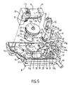
- FIG. 5 We will now refer to Figure 5 to describe the components of a second compartment 15 called kinematic of the lock housing B.
- This second compartment 15 is separated from sealed way of the compartment 3 by a partition which forms the bottom common to both compartments.
- the control lever 11 includes a stub shaft 11a which perpendicularly projecting towards the bottom of compartment 15 and which is inserted through the cylindrical sleeve 10 of the first compartment 3, the stub shaft 11 has provided at its free end a square section to fit into the opening corresponding square section 9b of the outer opening lever 9, for their rotational connection.
- the second compartment 15 contains a first electric motor 16 on the motor shaft which is coaxially mounted a first pinion 17 which meshes with a pinion of larger diameter 18 which is coaxially fixed in rotation with a worm 19.
- the assembly 16 to 19 form a geared motor group which is carried by support bearings 20, 21, which are anchored on the bottom of the compartment 15.
- the worm 19 meshes with the circumference of a toothed wheel 22 which comprises on its an upper side shaft end 22 is designed to be inserted in a suitable housing in the cover (not shown) for closing the second compartment 15. in its underside, the toothed wheel 22 is connected 23 to a wafer, by two crankpins 24, 25 diametrically opposed with respect to the axis of rotation of the wheel 22.
- the plate 23 further comprises a finger 23a projecting perpendicularly with respect to its plane and coming to be recessed in the underside of the a wheel 22.
- This finger 23 a is radially further out than the crank pins 24 and 25.
- the plate 23 comprises on its lower face a stub axis aligned with the tip of 22 a axis of the wheel 22, and intended to be inserted into a suitable housing 26 in the bottom of the compartment 15.
- One of said two crank pins namely the pin 24 furthest from the finger 23a of the wafer 23 is intended to cooperate with an arm 11b of the control lever 11 for rotating at the rotation of the wheel 22.
- the rotation of the control lever 11 simultaneously causes the rotation of the outer opening lever 9 in the retention compartment 3, to move the pawl 5 to the release position of the bolt.
- Rotation of the wheel 22 continues until the finger 23a of the wafer 23 comes into contact with an elastic stop limit switch 27 provided on the bottom of the compartment 15.
- This stop 27 is advantageously made of rubber, for damping the setting in support of the finger 23 has against this stop 27, because the drive by the motor 16 is relatively powerful.
- control lever 11 is subjected to a return spring, to return the lever of control 11 to its initial position, once the geared motor assembly has himself returned to his original position as he will explained further.
- a rubber stop 28 can also be provided in the compartment 15 to cushion the return of the lever of control 11 to its rest position, as shown in FIGS. to 9.
- the control lever 11 comprises at the free end of another arm, extending substantially in the opposite direction to the arm 11b , a pin 30 for cooperating with a downward curved tab 31 provided at the free end of an arm of an emergency lever 32.
- the emergency lever 32 is pivotally mounted on a shaft end 33 projecting from the bottom of the compartment 15 and comprises at the free end of another arm 34, arranged substantially in a direction opposite to the arm carrying the folded tab 31, a fork 35 whose two branches are provided at their free end with a guide ramp 35 a .
- a cable C passes between the branches of the fork 35 and has at its free end a tip 36 which has a substantially spherical shape whose diameter is greater than the spacing of the branches of the fork 35, so as to be able to cause the pivoting of the emergency lever 32 around its axis 33, by pulling on the cable C, from a means external control, for example an external handle or pallet door.
- the cable C is secured to a slider 37 arranged on the other side of the fork 35, relative to the tip 36.
- the cursor 37 can advantageously overmolded on the cable C.
- Two guide rails parallel 38, 39 are arranged on the bottom of the compartment 15 for used to guide the cursor 37 when moving the cable C.
- cable C extends outside the housing B, crossing, so waterproof, a sleeve 40.
- the kinematics compartment 15 further comprises a locking lever 41 which is articulated on a shaft end 42 projecting from the bottom of the compartment 15.
- the locking lever 41 comprises a first arm 43 provided at its free end with a pin 43a which engages in a helical groove 44a formed on a rotary drum 44.
- This rotary drum 44 is intended to be connected to a lock cylinder for a front door.
- the locking lever 41 comprises a second arm 45 extending substantially radially outwardly of the housing B, through an opening 46.
- the locking lever 41 has a third arm 47 which is intended to cooperate with the tip 36 of the cable C, to do so escape from the range 35, as shown in Figure 7.
- the tip 36 In the rest position of the cable C, the tip 36 is located in a recess of the locking lever 41 defined between the first arm 43 and the third arm 47.
- the locking lever 41 further comprises a sector toothed 48 which is extended at one end by a protruding stop 49.
- the toothed sector 48 meshes with a pinion 50 carried by the drive shaft 51 a second electric motor 52 for electrical assistance to the locking / unlocking.
- the second electric motor 52 is carried by a support piece 53 substantially C-shaped profile, which is mounted on the bottom of the compartment 15.
- the stop 49 of the locking lever 41 is intended to cooperate with a second lever having a bearing portion 54 extending radially from a shaft 55 which is mounted in a tubular sleeve 56 which protrudes from the bottom of the compartment 15.
- the shaft 55 passes through sealed manner, the bottom of the compartment 15 and present to its lower end a square section to be secured in rotation lever 13 mentioned above.
- an external opening contactor 60 which comprises a button 60 is adapted to be pushed by an inclined portion 37 a of the slider 37, during the traction of the cable C, for sending a control signal to opening to the first motor 16, by an electrical connection not shown.
- the locking lever 41 pivots in the counter-clockwise direction, as illustrated in FIG. 7.
- the lock is in its closed and mechanically condemned state, since the arm 47 of the locking lever 41 pushed the end piece 36 of the cable C in a direction substantially perpendicular to the actuating stroke of the cable C, so as to escape the endpiece 36 to the fork 35 of the emergency lever 32 .
- the flange 36 will slide along the arm 47 and the guide rail 35a of the fork 35, without driving the lever emergency 32, the lock can not be mechanically unlocked from the outside.
- the slider 37 connected to the cable C will move along the guide rails 38 and 39 and will come by its inclined portion 37 to push the switch button 60 a of the external opening contactor 60, but as the general power supply of the vehicle has not been activated, the electric motor 16 for opening assistance will remain inactive, thus also prohibiting the electric opening.
- crankpin 24 abuts against the arm 11b of the control lever 11 and pushes it back, so as to pivot the control lever 11 in the counter-clockwise direction in FIG. .
- the crank pin 24 pushes the arm 11b of the control lever 11 until the pin 23 has come into abutment against the resilient abutment limit switch 27.
- the pivoting of the control lever 11 causes the outer opening lever 9 to pivot in the retention compartment 3, in the clockwise direction in FIG. 4.
- the outer opening lever 9 pushes back by its arm 9 has the finger 5a of the pawl 5 to pivot in the anticlockwise direction the pawl 5, which thus frees the bolt 4 which can rotate, in turn, in the anti-clockwise to release the striker.
- the drive torque exerted by motor 16 will be maintained for a period of time determined by a time delay, to ensure that the crank pin 24 causes the pivoting of the control lever 11.
- the worm 19 will be rotated in the opposite direction by a spiral spring (no shown), to bring back the wheel 22 and thus, the crank pins 24 and 25 in their initial positions, to allow a subsequent opening.
- the spiral spring is connected to the worm 19 and wraps when the drive by the motor 16.
- the return spring spiral for the worm 19 is arranged in the bearing 20. In this configuration, the control lever 11 returns to its position rest under the action of a return spring not shown.
- the electrical assistance device for opening functions in the same way from the position of FIG. 7, in which the lock is in its closed and mechanically condemned state.
- the authorized user wearing a badge equipped with a transmitter to emit a given coded signal approaches the vehicle which is equipped with a recognition system comprising a receiver capable of decoding the signal and powering on. the power supply to the vehicle, where the authorized user has been duly identified.
- the contactor 60 sends a control signal simultaneously to the motor 16 and the motor 52, to cause simultaneously assistance in opening the door and unlocking others doors.
- the opening assistance device does not work, due to a power failure or insufficient power supply of the vehicle battery, the user can mechanically open the lock after having mechanically unlocked it, for example, by the lock cylinder, pulling on the cable C on an overtravel, to drive through the tip 36 the fork 35 of the emergency lever 32 which pivots clockwise in Figure 9 and pushes back by the curved tab 31 of its arm opposite the pin 30 of the control lever 11, to rotate it in the counterclockwise direction, which causes the pivoting of the outer opening lever 9, and consequently the release of the bolt.
- the arm 54 comes into contact with the stop 49 of the locking lever 41, due to cooperation between the cam 4a of the bolt 4 and the cam follower pin 13a of the lever 13.
- crankpin 25 shown in FIG. not present here particular usefulness.
- the electric motor 52 is reversible, in order to rotate the locking lever 41 in both directions, to bring it respectively in his condemned or unconditional position.
- the motor shaft 51 of the electric motor 52 has its axis of rotation parallel to the pivot axis of the locking lever 41, while the motor shaft of the electric motor 16 has its axis of rotation perpendicular to the axis of the opening lever 9.
Landscapes
- Lock And Its Accessories (AREA)
Description
- la figure 1 est une vue en perspective éclatée de la serrure conforme à l'invention, du côté de son compartiment de rétention ;
- la figure 2 est une vue analogue à la figure 1, mais partiellement assemblée ;
- la figure 3 est une vue de dessus de la figure 2, en position complètement assemblée de la serrure ;
- la figure 4 est une vue analogue à la figure 3, la contre-plaque étant omise ;
- la figure 5 est une vue en perspective éclatée de la serrure de l'invention, du côté de son compartiment de cinématique ;
- la figure 6 est une vue de dessus de la figure 5, le couvercle du compartiment de cinématique étant omis, et la serrure étant dans une position fermée et décondamnée ;
- la figure 7 est une vue analogue à la figure 6, mais représentant la serrure dans une position fermée et condamnée ;
- la figure 8 est une vue analogue à la figure 6, mais représentant la serrure dans une position ouverte et décondamnée, sous l'action du dispositif électrique d'assistance à l'ouverture ; et
- la figure 9 est une vue analogue à la figure 8, la serrure étant également en position ouverture et décondamnée, sous l'action du moyen mécanique de secours à l'ouverture.
- soit il se trouve à l'intérieur de l'habitacle du véhicule et il actionne un organe de manoeuvre situé sur l'intérieur de la portière pour commander le déplacement du bras 45 du levier de condamnation 41 ;
- soit l'utilisateur se trouve à l'extérieur du véhicule et il condamne la serrure avec sa clé en l'introduisant dans le barillet de serrure d'une portière avant pour entraíner, par l'intermédiaire du tonneau 44, le déplacement du bras 43 du levier de condamnation ;
- soit, enfin, de l'extérieur du véhicule, il actionne un boítier de télécommande portatif pour envoyer un signal de commande de condamnation au moteur électrique 52 d'assistance à la condamnation, lequel moteur 52 entraíne le pivotement du levier de condamnation 41, en agissant sur le secteur denté 48.
Claims (9)
- Serrure pour portière de véhicule automobile, comportant un boítier (B), un pêne (4) apte à retenir une gâche de portière, un cliquet (5) de blocage du pêne en position de retenue de la gâche, un mécanisme d'ouverture comportant au moins un moyen d'actionnement (9) apte à coopérer avec le cliquet pour l'amener dans une position de libération du pêne, sous l'action d'un moyen de commande intérieure ou extérieure, et un mécanisme de condamnation comportant un levier de condamnation (41) pour mettre la serrure dans une position condamnée ou décondamnée, et comportant en outre un moyen de décondamnation automatique à l'ouverture comportant, d'une part, un élément suiveur de came (13a) coopérant avec un profil de came (4a) prévu sur le pêne (4) et, d'autre part, une portion d'appui (54) apte à coopérer avec une butée (49) prévue sur le levier de condamnation (41), de façon que, lors de la rotation du pêne vers sa position d'ouverture, le profil de came entraíne un déplacement de l'élément suiveur de came et, par suite, de ladite portion d'appui de façon à amener automatiquement le levier de condamnation dans sa position de décondamnation,
le moyen de décondamnation automatique à l'ouverture comportant un premier levier (13) muni d'un pion suiveur de came (13a) coopérant avec le profil de came (4a) du pêne (4), et un deuxième levier solidaire en rotation du premier levier et muni de ladite portion d'appui apte à coopérer avec un pion de butée (49) sur le levier de condamnation (41),
caractérisée en ce que la serrure comporte un premier compartiment (3) du boítier (B) dans lequel se trouvent le premier levier (13) et le pêne (4), et un deuxième compartiment (15) du boítier (B) dans lequel se trouvent le deuxième levier et le levier de condamnation (41). - Serrure selon la revendication 1, caractérisée par le fait que, dans la position d'ouverture du pêne (4), la portion d'appui (54) du moyen de décondamnation automatique à l'ouverture bloque la butée (49) du levier de condamnation (41), ce qui interdit la condamnation de la serrure en position d'ouverture de la portière.
- Serrure selon la revendication 2 ou 3, caractérisée par le fait que le pion suiveur de came (13a) du premier levier (13) est apte à coopérer avec un contacteur de portière ouverte (14) en fin de course de rotation du pêne (4) vers sa position d'ouverture, ledit contacteur de portière ouverte étant destiné à émettre un signal correspondant à l'information d'ouverture de portière à une unité centrale de traitement.
- Serrure selon l'une des revendications 1 à 3, caractérisée par le fait que le moyen de décondamnation automatique à l'ouverture amène le levier de condamnation (41) en position décondamnée, avant la fin de course d'ouverture du pêne (4).
- Serrure selon l'une des revendications 1 à 4, caractérisée par le fait que le mécanisme de condamnation comporte un moteur électrique réversible (52) pour entraíner le levier de condamnation (41) entre ses positions condamnée et décondamnée, lors d'une condamnation ou décondamnation centralisée commandée de l'extérieur ou de l'intérieur.
- Serrure selon la revendication 5, caractérisée par le fait qu'elle est associée à un capteur de choc pour, lors de la détection d'un choc, envoyer un signal de commande au moteur électrique (52) du mécanisme de condamnation pour entraíner le levier de condamnation (41) vers sa position décondamnée.
- Serrure selon l'une des revendications 1 à 6, caractérisée par le fait que le moyen d'actionnement précité comporte un moyen mécanique de liaison, tel qu'un câble ou une tringle, reliant le cliquet (5) à un moyen de commande intérieure, par exemple une poignée ou palette intérieure de portière.
- Serrure selon l'une des revendications 1 à 7, caractérisée par le fait que le moyen d'actionnement comporte un levier d'ouverture extérieure (9) apte à coopérer avec le cliquet (5) pour l'amener en position de libération du pêne, ledit levier d'ouverture extérieure étant apte à être entraíné par un moteur électrique (16) pour l'assistance à l'ouverture, en réponse à un signal de commande émis par un contacteur d'ouverture extérieure (60), lorsqu'un moyen de commande extérieur est actionné par l'utilisateur.
- Serrure selon la revendication 8, caractérisée par le fait qu'elle comporte un moyen mécanique de liaison extérieure (C) dont une portion extérieure est destinée à être reliée au moyen de commande extérieure et dont une autre portion intérieure s'étend dans le deuxième compartiment étanche (15) de la serrure, ledit contacteur d'ouverture extérieure (60) étant disposé dans ledit deuxième compartiment étanche sur le trajet de ladite portion intérieure du moyen mécanique de liaison extérieure (C), de façon à émettre un signal de commande d'ouverture extérieure, lorsque le moyen de liaison mécanique est déplacé sur une course d'ouverture déterminée lors de l'actionnement du moyen de commande extérieure.
Applications Claiming Priority (2)
| Application Number | Priority Date | Filing Date | Title |
|---|---|---|---|
| FR9811740 | 1998-09-21 | ||
| FR9811740A FR2783550B1 (fr) | 1998-09-21 | 1998-09-21 | Serrure a decondamnation automatique a l'ouverture |
Publications (2)
| Publication Number | Publication Date |
|---|---|
| EP0989266A1 EP0989266A1 (fr) | 2000-03-29 |
| EP0989266B1 true EP0989266B1 (fr) | 2005-07-06 |
Family
ID=9530644
Family Applications (1)
| Application Number | Title | Priority Date | Filing Date |
|---|---|---|---|
| EP19990402278 Expired - Lifetime EP0989266B1 (fr) | 1998-09-21 | 1999-09-17 | Serrure à décondamnation automatique à l'ouverture |
Country Status (3)
| Country | Link |
|---|---|
| EP (1) | EP0989266B1 (fr) |
| DE (1) | DE69926038T2 (fr) |
| FR (1) | FR2783550B1 (fr) |
Families Citing this family (7)
| Publication number | Priority date | Publication date | Assignee | Title |
|---|---|---|---|---|
| DE10141310A1 (de) * | 2001-08-28 | 2003-03-20 | Kiekert Ag | Kraftfahrzeugtürverschluss |
| CN103774913B (zh) * | 2014-01-16 | 2016-05-04 | 王力安防产品有限公司 | 一种自动防盗门锁 |
| CN104895427B (zh) * | 2015-06-18 | 2017-05-24 | 无锡忻润汽车安全系统有限公司 | 可实现车门被冻情况下保证开锁状态的机构 |
| CN108118982B (zh) * | 2018-01-05 | 2024-09-10 | 东莞雅音电子科技有限公司 | 一种汽车电动门及其自动门锁装置 |
| DE102019103558A1 (de) * | 2018-02-15 | 2019-08-22 | Magna Closures Inc. | Verschluss-Verriegelungsanordnung für ein Kraftfahrzeug mit gemeinsamer kinematischer Kette für einen Kraft-Lösemechanismus und einen mechanischen Sicherungs-Lösemechanismus |
| CN110528968B (zh) * | 2019-09-26 | 2024-07-16 | 北京享易天下科技有限公司 | 一种用于共享设备的锁具及共享设备 |
| CN112523622B (zh) * | 2020-12-18 | 2024-08-06 | 常州市武进华瑞电子有限公司 | 一种具有自锁机构的电池仓锁装置 |
Family Cites Families (4)
| Publication number | Priority date | Publication date | Assignee | Title |
|---|---|---|---|---|
| DE2442797A1 (de) * | 1974-09-06 | 1976-03-18 | Volkswagenwerk Ag | Drehfallenschloss, insbesondere fuer eine kraftfahrzeugtuer |
| DE4240013A1 (de) * | 1992-08-25 | 1994-06-01 | Bayerische Motoren Werke Ag | Fernsteuerbares Schloß, insbesondere für Kraftfahrzeugtüren |
| GB2306550B (en) * | 1995-10-20 | 1999-12-15 | Rockwell Lvs | Vehicle door latch assembly |
| DE19600524B4 (de) * | 1995-12-20 | 2006-07-06 | Siemens Ag | Schloß, insbesondere für Kraftfahrzeugtüren |
-
1998
- 1998-09-21 FR FR9811740A patent/FR2783550B1/fr not_active Expired - Fee Related
-
1999
- 1999-09-17 EP EP19990402278 patent/EP0989266B1/fr not_active Expired - Lifetime
- 1999-09-17 DE DE69926038T patent/DE69926038T2/de not_active Expired - Lifetime
Also Published As
| Publication number | Publication date |
|---|---|
| DE69926038T2 (de) | 2006-05-11 |
| FR2783550A1 (fr) | 2000-03-24 |
| EP0989266A1 (fr) | 2000-03-29 |
| FR2783550B1 (fr) | 2000-12-29 |
| DE69926038D1 (de) | 2005-08-11 |
Similar Documents
| Publication | Publication Date | Title |
|---|---|---|
| EP0989264B1 (fr) | Serrure électrique perfectionnée pour portière de vehicule automobile | |
| EP0959206B1 (fr) | Serrure de porte de véhicule automobile à condamnation électrique | |
| EP1001119B1 (fr) | Serrure de porte à condamnation/décondamnation électrique extérieure et/ou intérieure pour véhicule automobile | |
| EP0807734B1 (fr) | Serrure pour une portière de véhicule automobile | |
| EP1030014A1 (fr) | Serrure en trois parties, pour ouvrant de véhicule automobile | |
| FR2501271A1 (fr) | Serrure, notamment pour portiere de vehicule automobile | |
| EP1030012B1 (fr) | Serrure pour ouvrant de véhicule automobile, à mémorisation de décondamnation | |
| EP1138853A2 (fr) | Poignée pour dispositif de commande de l'ouverture d'une serrure d'un ouvrant de véhicule automobile | |
| EP0012633B1 (fr) | Dispositif de condamnation et de commande d'ouverture de la porte de coffre d'un véhicule automobile | |
| EP0953701A1 (fr) | Serrure de porte de véhicule automobile | |
| FR2852993A1 (fr) | Serrure pour ouvrant de vehicule automobile, a memorisation de decondamnation/condamnation | |
| EP1099810A1 (fr) | Dispositif de commande d'un mécanisme de verrouillage d'une porte d'un véhicule | |
| FR2654767A1 (fr) | Mecanisme de commande d'ouverture d'une portiere de vehicule automobile et portiere le comportant. | |
| EP3879051A1 (fr) | Commande d'ouverture exterieure de porte de vehicule automobile | |
| FR2775717A1 (fr) | Dispositif d'ouverture/fermeture d'un ouvrant, notamment pour vehicule automobile | |
| FR2919647A1 (fr) | Serrure electrique pour ouvrant, notamment de vehicule automobile. | |
| FR2803619A1 (fr) | Module de serrure electrique pour une porte d'un vehicule | |
| EP0989265B1 (fr) | Serrure simplifiée pour portière de vèhicule automobile | |
| EP0292361B1 (fr) | Serrure comportant un mécanisme de déverrouillage à fonctionnement électrique | |
| EP1004730B1 (fr) | Serrure pour portière avant ou arrière de véhicule automobile | |
| EP3775452B1 (fr) | Dispositif d'ouverture d'un ouvrant et véhicule équipé d'un tel dispositif | |
| EP0989266A1 (fr) | Serrure à décondamnation automatique à l'ouverture | |
| EP1004731A1 (fr) | Serrure pour portière de véhicule automobile | |
| FR2782108A1 (fr) | Serrure de fermeture pour une porte de vehicule automobile et vehicule automobile equipe de cette serrure | |
| FR2930201A1 (fr) | Trappe a carburant verrouillable pour vehicule automobile. |
Legal Events
| Date | Code | Title | Description |
|---|---|---|---|
| PUAI | Public reference made under article 153(3) epc to a published international application that has entered the european phase |
Free format text: ORIGINAL CODE: 0009012 |
|
| AK | Designated contracting states |
Kind code of ref document: A1 Designated state(s): DE ES GB IT SE |
|
| AX | Request for extension of the european patent |
Free format text: AL;LT;LV;MK;RO;SI |
|
| 17P | Request for examination filed |
Effective date: 20000808 |
|
| AKX | Designation fees paid |
Free format text: DE ES GB IT SE |
|
| 17Q | First examination report despatched |
Effective date: 20010731 |
|
| RAP1 | Party data changed (applicant data changed or rights of an application transferred) |
Owner name: VALEO SECURITE HABITACLE S.A.S. |
|
| GRAP | Despatch of communication of intention to grant a patent |
Free format text: ORIGINAL CODE: EPIDOSNIGR1 |
|
| GRAS | Grant fee paid |
Free format text: ORIGINAL CODE: EPIDOSNIGR3 |
|
| GRAA | (expected) grant |
Free format text: ORIGINAL CODE: 0009210 |
|
| AK | Designated contracting states |
Kind code of ref document: B1 Designated state(s): DE ES GB IT SE |
|
| PG25 | Lapsed in a contracting state [announced via postgrant information from national office to epo] |
Ref country code: IT Free format text: LAPSE BECAUSE OF FAILURE TO SUBMIT A TRANSLATION OF THE DESCRIPTION OR TO PAY THE FEE WITHIN THE PRESCRIBED TIME-LIMIT;WARNING: LAPSES OF ITALIAN PATENTS WITH EFFECTIVE DATE BEFORE 2007 MAY HAVE OCCURRED AT ANY TIME BEFORE 2007. THE CORRECT EFFECTIVE DATE MAY BE DIFFERENT FROM THE ONE RECORDED. Effective date: 20050706 Ref country code: GB Free format text: LAPSE BECAUSE OF FAILURE TO SUBMIT A TRANSLATION OF THE DESCRIPTION OR TO PAY THE FEE WITHIN THE PRESCRIBED TIME-LIMIT Effective date: 20050706 |
|
| REG | Reference to a national code |
Ref country code: GB Ref legal event code: FG4D Free format text: NOT ENGLISH |
|
| REF | Corresponds to: |
Ref document number: 69926038 Country of ref document: DE Date of ref document: 20050811 Kind code of ref document: P |
|
| PG25 | Lapsed in a contracting state [announced via postgrant information from national office to epo] |
Ref country code: SE Free format text: LAPSE BECAUSE OF FAILURE TO SUBMIT A TRANSLATION OF THE DESCRIPTION OR TO PAY THE FEE WITHIN THE PRESCRIBED TIME-LIMIT Effective date: 20051006 |
|
| PG25 | Lapsed in a contracting state [announced via postgrant information from national office to epo] |
Ref country code: ES Free format text: LAPSE BECAUSE OF FAILURE TO SUBMIT A TRANSLATION OF THE DESCRIPTION OR TO PAY THE FEE WITHIN THE PRESCRIBED TIME-LIMIT Effective date: 20051017 |
|
| GBV | Gb: ep patent (uk) treated as always having been void in accordance with gb section 77(7)/1977 [no translation filed] |
Effective date: 20050706 |
|
| PLBE | No opposition filed within time limit |
Free format text: ORIGINAL CODE: 0009261 |
|
| STAA | Information on the status of an ep patent application or granted ep patent |
Free format text: STATUS: NO OPPOSITION FILED WITHIN TIME LIMIT |
|
| 26N | No opposition filed |
Effective date: 20060407 |
|
| REG | Reference to a national code |
Ref country code: DE Ref legal event code: R082 Ref document number: 69926038 Country of ref document: DE |
|
| REG | Reference to a national code |
Ref country code: DE Ref legal event code: R081 Ref document number: 69926038 Country of ref document: DE Owner name: U-SHIN FRANCE SAS, FR Free format text: FORMER OWNER: VALEO SECURITE HABITACLE S.A.S., CRETEIL, FR Effective date: 20150515 |
|
| PGFP | Annual fee paid to national office [announced via postgrant information from national office to epo] |
Ref country code: DE Payment date: 20180913 Year of fee payment: 20 |
|
| REG | Reference to a national code |
Ref country code: DE Ref legal event code: R071 Ref document number: 69926038 Country of ref document: DE |