EP0988474B1 - Flüssigkeitsgetriebe - Google Patents
Flüssigkeitsgetriebe Download PDFInfo
- Publication number
- EP0988474B1 EP0988474B1 EP98926234A EP98926234A EP0988474B1 EP 0988474 B1 EP0988474 B1 EP 0988474B1 EP 98926234 A EP98926234 A EP 98926234A EP 98926234 A EP98926234 A EP 98926234A EP 0988474 B1 EP0988474 B1 EP 0988474B1
- Authority
- EP
- European Patent Office
- Prior art keywords
- fluid
- housing
- turbine
- pressure
- shaft
- Prior art date
- Legal status (The legal status is an assumption and is not a legal conclusion. Google has not performed a legal analysis and makes no representation as to the accuracy of the status listed.)
- Expired - Lifetime
Links
Images

Classifications
-
- F—MECHANICAL ENGINEERING; LIGHTING; HEATING; WEAPONS; BLASTING
- F16—ENGINEERING ELEMENTS AND UNITS; GENERAL MEASURES FOR PRODUCING AND MAINTAINING EFFECTIVE FUNCTIONING OF MACHINES OR INSTALLATIONS; THERMAL INSULATION IN GENERAL
- F16H—GEARING
- F16H41/00—Rotary fluid gearing of the hydrokinetic type
- F16H41/02—Rotary fluid gearing of the hydrokinetic type with pump and turbine connected by conduits or ducts
-
- B—PERFORMING OPERATIONS; TRANSPORTING
- B62—LAND VEHICLES FOR TRAVELLING OTHERWISE THAN ON RAILS
- B62M—RIDER PROPULSION OF WHEELED VEHICLES OR SLEDGES; POWERED PROPULSION OF SLEDGES OR SINGLE-TRACK CYCLES; TRANSMISSIONS SPECIALLY ADAPTED FOR SUCH VEHICLES
- B62M19/00—Transmissions characterised by use of non-mechanical gearing, e.g. fluid gearing
Definitions
- the present invention pertains to fluid drive systems. More particularly, one embodiment of the present invention concerns a drive system for bicycles.
- Kubeczka discloses a high pressure radial pump for delivering a stream of liquid at high velocity for cleaning of various surfaces.
- Harriger describes a hydraulic drive system having a variable speed drive mechanism.
- Yamamura et al. disclose a hydraulic radial piston pump having a set of pistons arranged radially around the rotary shaft for sequential reciprocating motion for suction and delivery of working oil.
- Becoat describes a dual wheel driven bicycle which uses an elongate flexible shaft or cable to provide rotational movement to the front wheel.
- Bublitz discloses a sequential displacement piston pump.
- Kadaja describes a hydraulic drive mechanism for tricycles and the like that comprises a variable volume, positive displacement hydraulic pump and a hydraulic motor.
- U.S. Patent No. 5,358,078, issued on 25 October 1994 to Fichtel & Sachs, AG discloses a hydraulically operable disk brake for bicycles or similar vhicles.
- FR-A-2477659 discloses a hydraulic gear selector with a motor turbine connected to a plurality of output turbines. Gear selection is performed by a hydraulic mechanism located between the turbines in a common housing.
- US-A-4,864,143 discloses a bicycle with a fluid pump arranged at the pedals connected by means of hydraulic passages to a fluid motor located at a rear or front wheel.
- the pump is of the radial plunger type and includes a cam assembly with adjustable eccentricity.
- FR-A-714,638 describes force. transmission by a liquid and represents prior art within the meaning of Rule 29(1)(a) EPC.
- the present invention provides an apparatus according to claim 1.
- embodiments of the present invention comprise a torque converting linkage which employs two turbines in fluid filled chambers.
- An external torque rotates the first turbine, which forces fluid into a chamber containing a second turbine.
- the displaced fluid rotates the second turbine, furnishing rotational power to a device attached to a shaft which the second turbine rotates.
- the housings enclosing the two turbines are filled with a force transmitting fluid, and are coupled by two conduits.
- Each housing has an inlet and an outlet which provide connections for the conduits.
- the housing includes a volute which directs fluid against the vanes of the turbines to optimize the transfer of energy.
- Embodiments of the invention also include a ratio adjustment device, which controls the flow of fluid to the turbines, and a pressure adjustment device, which changes the working pressure within the housings.
- Other features which may be incorporated into the invention include a quick connect device, a dual flow conduit, a dual flow quick connect device, a reversing valve and automatic shifting and torque adjustment devices.
- One embodiment of the invention is intended for use with bicycles.
- the invention offers the advantage of transferring power from one location to another even if the two shafts are not in line, or if the two turbines are not mounted in the same plane or their locations are moving with respect to each other.
- the invention may be utilized in a wide variety of mechanical devices, including automobiles, machinery, tools and appliances. Further embodiments of the invention are defined in the dependent claims.
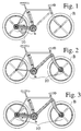
- Figures 1, 2 and 3 show different embodiments of the present invention 10 mounted on a conventional bicycle B.
- Figures 4, 5 and 6 reveal the details of a generalized embodiment of the present invention 11.
- the embodiment portrayed in Figures 4, 5 and 6 comprises two disc-shaped turbines 12 and 14 which rotate on shafts 16 and 18, and which are enclosed by housings 20 and 22.
- Each housing has a pair of fluid ports, an inlet and outlet.
- the inlet and outlet ports on the impeller turbine housing 20 are marked 24 and 34.
- the inlet and outlet ports on the reactor turbine housing 22 are marked 26 and 28.
- the two housings 20 and 22 are coupled by a pair of conduits 32 and 34, forming a closed loop.
- Conduit 32 the driver conduit
- Conduit 34 the return conduit
- Conduit 32 the return conduit
- Conduit 34 the return conduit
- the housings 20 and 22, as well as the conduits 32 and 34, are all filled with a generally incompressible fluid 36.
- the first turbine functions as an impeller 12, which is rotated by an external force which is applied to the impeller turbine shaft 16.
- the second turbine functions as a reactor 14, which is turned by the motion of the fluid 36 that is forced by direct pressure away from the impeller turbine 12 and through driver conduit 32.
- the fluid 36 then acts on the passive reactor turbine 14, inducing the reactor turbine 14 to rotate its shaft 18.
- the spent fluid 36 then returns to the housing containing the impeller turbine 12 through return conduit 34.
- the fluid 36 is a natural or synthetic gel or lubricant that is capable of withstanding high temperatures and that has a very low freezing temperature.
- Each turbine 12, 14 includes generally spiral-shaped vanes 38 which radiate from their centers.
- the vanes 38 each have a convex and a concave side.
- the impeller turbine 12 is shown rotating in the clockwise direction as a result of the external torque imposed on shaft 16.
- a crank with pedals would be fixed to shaft 16.
- the fluid 36 is "caught” against the concave side of each vane 38 and pushed out of the impeller housing 20 into its outlet port 24, which is connected to driver conduit 32.
- the fluid 36 then enters the reactor housing 22 through its inlet port 26, and is then caught by the vanes 28 on the concave side of the reactor turbine 14.
- the displaced fluid forces the reactor turbine 14 to rotate its shaft 18, and then exits the reactor housing 22 by passing through reactor housing outlet port 28 into the return conduit 34.
- the fluid 36 completes its journey by arriving back in the impeller housing 20 through its inlet port 30.
- FIGS 4, 5 and 6 are generalized versions of the invention, and are provided only to disclose the invention in one of its more simple forms.
- the turbines 12 and 14 represent only one of the many embodiments of the invention.
- the spiral vanes 38 constitute only one of the many variations which may be employed to implement the invention. Any means which transmits a medium under pressure from a first rotating turbine to a second rotating turbine may be utilized to practice the invention.
- Figure 5 discloses an important benefit offered by embodiments of the invention. Because the conduits 32 and 34 may be flexible, the turbines 12 and 14 may be located in different planes as shown in Figure 5. Unlike a conventional chain drive on a bicycle, where the rotating sprockets must be located in-line and generally in the same plane in a fixed location, embodiments of the present invention offers a means for transmitting power without the geometric constraints of previous mechanical drive systems. The rotating shafts and associated housing and turbines may be moved to other non coplanar locations with respect to each other while in operation.
- Figure 6 illustrates an alternative embodiment of the invention, showing the housings 20 and 22 connected in a configuration which is different from that shown in Figure 4.
- the impeller and the reactor turbines rotate in opposite directions.
- both turbines may be made to rotate in the same direction.
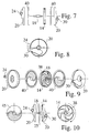
- Figure 7 furnishes an exploded view of an embodiment of the present invention which includes a turbine 14, a shaft 18, a housing 20, inlet and outlet ports 24 and 30, and a volute 40.
- the volute 40 comprises two pieces and encloses the turbine (14) within the turbine housing (20).
- the volute may be a generally disc-shaped element which is shaped to direct the flow of the fluid 26 within the housing to optimize the transfer of power to and from the turbines.
- the volute 40 may comprise two separate pieces which are installed on either side of a turbine, or may be integrally formed as part of a housing.
- the volute 40 may be an integral part of one of said housing means 20, 22 or may be in the form of a replaceable cartridge.
- the volute 40 may have a number of openings formed in its sides, or may incorporate venturi or contours which are designed to direct the fluid flow within a turbine housing.
- Figure 8 presents a side view of the housing 20, showing an inlet and an outlet port 24 and 30.
- Figure 9 offers another exploded rendering, depicting the turbine 14, shaft 18, housing 20 and volute 40 in a perspective view.
- Figure 10 furnishes yet another illustration of this same embodiment of the present invention.
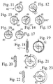
- Figures 11, 12, 13, 14 and 15 contain sequential views of a ratio adjustinent device 42, which functions as an adjustable aperture or iris that controls fluid flow to or from the turbines.
- the ratio adjustment device 42 changes the torque ratio and/or speed of one of the shafts with respect to another of the turbine shafts.
- the ratio adjustment device 42 comprises two discs mounted side by side. Both the first fixed disc 44 and the second movable disc 46 are formed with spiral-shaped openings 48. The second movable disc 46 is rotated so that the overlap of the spiral openings on each disc create a variable aperture for the flow of the force transmitting fluid 36.
- the volume and position of fluid that flows to a turbine is determined by the size and shape of the opening that is created by the superposition of the two discs 44 and 46.
- Figures 16 and 17 contain additional views of the ratio adjustment device.
- the ratio adjustment device 42 may be integrated with a volute 40 or with a housing 20, of may be manufactured as a separate unit.
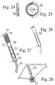
- the ratio adjustment device 42 may be controlled by a variety of different mechanisms, including a lever, a cable, a belt, gears, rollers or springs or magnetic actuator, as shown in Figures 18 through 25.
- Figures 26, 27 and 28 illustrate a pressure adjustment device 50 that is used to control the fluid pressure inside the turbine housings 20 and 22.
- the pressure adjustment device 50 comprises a pump which increases or reduces the pressure in the space inside one or both of the housings 20, 22.
- Figure 27 depicts a pressure adjustment device 50 comprising a housing 52, a pressure gauge 54, a release valve 56, a bladder membrane 58, a pumping mechanism 53 and a vent 60.
- Figure 28 shows a pressure adjustment device 50 mounted on a bicycle frame. The pressure adjustment device may also be employed to capture any gas that may accumulate in the force transmitting fluid 36.
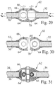
- Figures 29, 30 and 31 reveal the details of a quick connect assembly 62 that may be used to connect or disconnect the fluid conduits 32 and 34 from the turbine housings 20 and 22.
- the quick connect assembly 62 includes two pivoting ball valves 64 located in a housing 66. One of the balls has a mating surface dimple 68, while the other has a mating surface ring 70.
- the use of the quick connect assembly 62 allows for quick and easy decoupling without re-pressurizing or bleeding the system. This feature is especially useful when the invention is incorporated with a bicycle, where it is important to be able to remove and to reattach the front or rear wheel frequently.
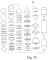
- Figure 32 supplies views of some of the various impeller configurations 72 which may be used to implement the invention. Then depictions are provided to educate the reader about the wide variety of embodiments which may be employed to practice the invention, and are not intended to limit the scope of the Claims which follow.
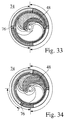
- Figures 33 and 34 provide illustrations of an auto-dial assembly 74, which is used to adjust the ratio adjustment device to maintain constant torque pressure on the driver turbine.
- the auto-dial assembly 74 utilizes the pressure differential between the two ports of a housing to automatically control the ratio adjustment device 42.
- An auto-dial pressure adjuster 76 is moved by increasing the pressure of the fluid flowing through an internal port. This action, in turn, rotates the movable disc 46 of the ratio adjustment device 42.
- Embodiments of the invention may also include a torque adjustment device which uses the pressure differential of the fluid at the two ports on a housing to automatically adjust the ratio adjustment device 42.
- a torque adjustment device which uses the pressure differential of the fluid at the two ports on a housing to automatically adjust the ratio adjustment device 42.
- Embodiments of the invention may also include a dual flow conduit incorporating the driver conduit 32 and the return conduit 34 into a single element.
- Embodiments of the invention may also include dual flow impeller housing inlet/outlet parts incorporating impeller housing inlet port 30 and impeller housing outlet port 24 into one element.
- Embodiments of the invention may also include dual flow reactor housing inlet/outlet parts incorporating reactor housing inlet port and reactor housing outlet port 28 into one element.
- Embodiments of the invention may also include a dual flow quick disconnect assembly to allow quick and easy disconnection and re-connection of dual flow conduit to dual flow impeller housing inlet/outlet port or dual flow reactor inlet/outlet port.
- Embodiments of the invention may also indude a reversing valve which redirects the direction of fluid flow through the housings 20 and 22.
- One embodiment of the present invention is intended for use with bicycles.
- the invention may also be employed in a wide variety of mechanical devices, including automobiles, machinery, tools and appliances.
Landscapes
- Engineering & Computer Science (AREA)
- Mechanical Engineering (AREA)
- General Engineering & Computer Science (AREA)
- Chemical & Material Sciences (AREA)
- Combustion & Propulsion (AREA)
- Transportation (AREA)
- Control Of Turbines (AREA)
- Control Of Fluid Gearings (AREA)
- Hydraulic Turbines (AREA)
- Structures Of Non-Positive Displacement Pumps (AREA)
- Fluid-Driven Valves (AREA)
- Fluid-Pressure Circuits (AREA)
- Transmission Devices (AREA)
- Thermally Insulated Containers For Foods (AREA)
Claims (22)
- Vorrichtung, umfassend:gekennzeichnet durch ein Verhältniseinstellmittel (42) zum Ändern des Verhältnisses der Drehmomente des ersten Wellenmittels (16) und des zweiten Wellenmittels (18), wobei das Verhältniseinstellmittel (42) um eines des ersten Wellenmittels (16) und des zweiten Wellenmittels (18) herum angeordnet ist und eine feste Scheibe (44) und eine drehbare Scheibe (46) aufweist, wobei sowohl die feste Scheibe (44) als auch die drehbare Scheibe Blenden (48) aufweisen, wobei die Scheiben (44, 46) Seite an Seite angebracht sind, so dass die Turbinen das Fluid durch das Verhältniseinstellmittel (42) in im Wesentlichen axialer Richtung drücken.ein erstes Gehäusemittel (20) zur Aufnahme eines Fluids und das einen Einlassdurchgang (30) und einen Auslassdurchgang (24) enthält;ein zweites Gehäusemittel (22) zur Aufnahme des Fluids und das einen Einlassdurchgang (26) und einen Auslassdurchgang (28) enthält;ein erstes Leitungsmittel (32) und ein zweites Leitungsmittel (34) zum Fördern des Fluids zwischen dem ersten Gehäusemittel (20) und dem zweiten Gehäusemittel (22);ein erstes Turbinenmittel (12), das in dem ersten Gehäusemittel (20) aufgenommen ist und ein erstes Wellenmittel (16) enthält, um ein externes Drehmoment auf das erste Turbinenmittel (12) zu übertragen, wobei das erste Turbinenmittel (12) das externe Drehmoment in einen auf das Fluid ausgeübten Druck umwandelt;ein zweites Turbinenmittel (14), das in dem zweiten Gehäusemittel (22) aufgenommen ist, um den auf das Fluid ausgeübten Druck in Rotationsenergie umzuwandeln, und das ein zweites Wellen mittel (18) enthält, um die Rotationsenergie in ein externes Drehmoment zu überführen;
- Vorrichtung nach Anspruch 1, worin die Blenden spiralförmige Öffnungen (48) sind.
- Vorrichtung nach einem der vorhergehenden Ansprüche, die ferner ein Mittel (74) aufweist, um das Verhältniseinstellmittel (42) automatisch zu steuern/zu regeln.
- Vorrichtung nach Anspruch 3, worin das automatische Steuermittel (74) einen Druckeinsteller (76) aufweist, der durch Ändern des Drucks des Fluids bewegt wird und der wiederum eine drehbare Scheibe (46) des Verhältniseinstellmittels (42) dreht.
- Vorrichtung nach einem der vorhergehenden Ansprüche, die ferner ein Drehmomenteinstellmittel umfasst, um die Druckdifferenz des Fluids an den Durchgängen (24, 30; 26, 28) an den Gehäusemitteln (20, 22) zu nutzen, um das Verhältniseinstellmittel (42) automatisch einzustellen.
- Vorrichtung nach einem der vorhergehenden Ansprüche, die ferner ein Druckeinstellmittel (50) umfasst, um den Druck innerhalb eines oder jedes der Gehäusemittel (20, 22) zu steuern/zu regeln.
- Vorrichtung nach Anspruch 6, worin das Druckeinstellmittel (50) eine Pumpe ist.
- Vorrichtung nach Anspruch 6 oder 7, worin das Druckeinstellmittel (50) eine Lüftung (60) enthält.
- Vorrichtung nach Anspruch 7 oder 8, worin das Druckeinstellmittel (50) verwendet wird, um etwaiges Gas zu fangen, das sich in dem Fluid (36) ansammeln könnte.
- Vorrichtung nach einem der vorhergehenden Ansprüche, die ferner ein Selbstwählmittel (74) umfasst, um das Verhältniseinstellmittel (42) automatisch zu steuern/zu regeln.
- Vorrichtung nach Anspruch 10, die ferner einen Druckeinsteller (76) umfasst, der durch Verändern des Drucks des Fluids (36) bewegt wird, der wiederum eine drehbare Scheibe (46) des Verhältniseinstellmittels (42) dreht.
- Vorrichtung nach einem der vorhergehenden Ansprüche, worin die Leitungsmittel durch langgestreckte flexible Elemente (32, 34) gebildet sind.
- Vorrichtung nach einem der vorhergehenden Ansprüche, die femer ein Schnellverbindungsmittel (62) umfasst, um das Leitungsmittel (32, 34) mit dem Gehäusemittel (20, 22) zu koppeln oder davon zu entkoppeln.
- Vorrichtung nach Anspruch 13, worin das Schnellverbindungsmittel (62) ein Paar von in einem Gehäuse (66) befindlichen Schwenkkugelventilen (64) aufweist, die zusammen sperren, um eine Passage für das Fluid zu bilden.
- Vorrichtung nach einem der vorhergehenden Ansprüche, die ferner ein Ausströmmittel (40) aufweist, um den Fluidfluss innerhalb des oder jedes Gehäusemittels (20, 22) auszurichten, um die Kraftübertragung zu und von dem Turbinenmittel (12, 14) zu optimieren.
- Vorrichtung nach Anspruch 15, worin das Ausströmmittel (40) ein integraler Teil eines der Gehäusemittel (20, 22) ist.
- Vorrichtung nach Anspruch 15, worin das Ausströmmittel (40) eine austauschbare Patrone ist.
- Vorrichtung nach einem der Ansprüche 15 bis 17, worin das Ausströmmittel (40) allgemein scheibenförmig ist.
- Vorrichtung nach einem der Ansprüche 15 bis 18, worin das Ausströmmittel (40) eine an seiner Seite ausgebildete Öffnung enthält.
- Vorrichtung nach einem der vorhergehenden Ansprüche, worin jedes Turbinenmittel (12, 14) allgemein spiralförmige Flügel (38) aufweist, die von der Mitte des Turbinenmittels abstrahlen und eine konvexe Seite und eine konkave Seite aufweisen, wobei das Fluid so angeordnet wird, dass es durch die konkaven Seiten der Flügel aufgefangen wird.
- Vorrichtung nach einem der vorhergehenden Ansprüche, die ferner ein Umkehrventil aufweist, das die Richtung des Fluidflusses durch das Gehäusemittel (20 oder 22) umkehrt.
- Fahrrad (B), das eine Vorrichtung gemäß einem der vorhergehenden Ansprüche aufweist, worin Pedale des Fahrrads mit dem Wellenmittel (16) des ersten Turbinenmittels (12) antriebsmäßig verbunden sind und die Wellenmittel (18) von einem oder mehreren zweiten Turbinenmitteln (14) so angeordnet sind, dass sie mit jeweiligen Rädern des Fahrrads antriebsmäßig verbunden sind.
Applications Claiming Priority (3)
| Application Number | Priority Date | Filing Date | Title |
|---|---|---|---|
| US5098897P | 1997-06-21 | 1997-06-21 | |
| US50988P | 1997-06-21 | ||
| PCT/US1998/011411 WO1998059188A1 (en) | 1997-06-21 | 1998-06-10 | Fluidic drive apparatus |
Publications (2)
| Publication Number | Publication Date |
|---|---|
| EP0988474A1 EP0988474A1 (de) | 2000-03-29 |
| EP0988474B1 true EP0988474B1 (de) | 2004-09-29 |
Family
ID=21968695
Family Applications (1)
| Application Number | Title | Priority Date | Filing Date |
|---|---|---|---|
| EP98926234A Expired - Lifetime EP0988474B1 (de) | 1997-06-21 | 1998-06-10 | Flüssigkeitsgetriebe |
Country Status (9)
| Country | Link |
|---|---|
| US (1) | US6164404A (de) |
| EP (1) | EP0988474B1 (de) |
| JP (1) | JP4185995B2 (de) |
| CN (1) | CN1147669C (de) |
| AT (1) | ATE278127T1 (de) |
| AU (1) | AU7811798A (de) |
| CA (1) | CA2294001C (de) |
| DE (1) | DE69826658T2 (de) |
| WO (1) | WO1998059188A1 (de) |
Cited By (1)
| Publication number | Priority date | Publication date | Assignee | Title |
|---|---|---|---|---|
| EP2426313B1 (de) * | 2010-09-07 | 2017-05-24 | Chun-Chieh Chen | Wandler mit zentrifugalen Impellern |
Families Citing this family (10)
| Publication number | Priority date | Publication date | Assignee | Title |
|---|---|---|---|---|
| IT1316546B1 (it) * | 2000-11-16 | 2003-04-22 | Dag Horses S R L Ora Mytym S R | Struttura di mezzo di locomozione. |
| ITTS20030018A1 (it) * | 2003-08-08 | 2005-02-09 | Alberto Rizzi | Propulsore idraulico con capsula posteriore per bicicletta |
| EP1766235B1 (de) * | 2004-07-13 | 2017-04-19 | Energy Recovery, Inc. | Hydraulischer Turboverdichter |
| DE102005009821B3 (de) * | 2004-11-16 | 2006-07-20 | Stefan Matuzic | Hydraulische Antriebseinheit |
| CN202215509U (zh) * | 2011-09-01 | 2012-05-09 | 陈俊杰 | 双离心式叶轮结构 |
| US9194233B2 (en) | 2013-02-13 | 2015-11-24 | William W. Cochran | Disk turbine using heat pipes |
| DE102015002338A1 (de) | 2015-02-24 | 2016-08-25 | Stefan Matuzic | Fahrradantrieb mit Hydrauliksystem |
| CN108626338A (zh) * | 2018-06-12 | 2018-10-09 | 楼荣平 | 一种动力纤传动机构 |
| ES2857423B2 (es) * | 2021-04-21 | 2024-03-07 | Bendito Vallori Sebastian Enrique | Sistema hidráulico de trasmisión con desarrollos por control electromagnético para vehículos, con generación y propulsión eléctrica discrecional |
| US20250060028A1 (en) | 2022-04-18 | 2025-02-20 | Sebastián Enrique Bendito Vallori | Electromagnetically controlled hydraulic transmission system with gears for vehicles, with optional electrical generation and propulsion |
Family Cites Families (28)
| Publication number | Priority date | Publication date | Assignee | Title |
|---|---|---|---|---|
| US1061142A (en) * | 1909-10-21 | 1913-05-06 | Nikola Tesla | Fluid propulsion |
| FR714638A (fr) * | 1930-07-26 | 1931-11-17 | Avions Bernard Soc D | Transmission de force par liquide en mouvement à vitesse variable |
| FR976447A (fr) * | 1948-12-13 | 1951-03-19 | Transmission hydraulique de force | |
| US3850448A (en) | 1972-07-13 | 1974-11-26 | G Stewart | Pressurized driving mechanism |
| US3941075A (en) * | 1975-03-12 | 1976-03-02 | Rupenian Emanuel A | Pedal powered amphibian tricycle with blower-turbine coupling means |
| US4313714A (en) | 1979-10-01 | 1982-02-02 | Kubeczka Johnny D | High pressure radial pump |
| FR2477659A1 (fr) * | 1980-03-10 | 1981-09-11 | Sepahi Donboly Gholam | Groupe hydraulique d'entrainement a selecteur de vitesses |
| US4546990A (en) | 1983-09-06 | 1985-10-15 | Harriger George A | Hydraulic drive system for bicycles and the like |
| US4568097A (en) * | 1984-01-16 | 1986-02-04 | Farooq Anwar M | Turbo air motor for bicycles |
| US4688815A (en) | 1984-03-27 | 1987-08-25 | Lectrolarm Custom Systems, Inc. | Hydraulically driven bicycle |
| JPS61229685A (ja) | 1985-04-05 | 1986-10-13 | ブリヂストンサイクル株式会社 | 二輪車 |
| US5116070A (en) | 1989-09-08 | 1992-05-26 | Becoat Billie J | Dual wheel driven bicycle |
| US5230519A (en) | 1988-02-16 | 1993-07-27 | Honda Giken Kogyo Kabushiki Kaisha | Hydraulically operated power transmission apparatus |
| JPH0216370A (ja) | 1988-07-01 | 1990-01-19 | Kayaba Ind Co Ltd | ラジアルピストンポンプ |
| US5112111A (en) | 1990-12-10 | 1992-05-12 | Addington Resources, Inc. | Apparatus and method for continuous mining |
| DE4127751C1 (de) | 1991-08-22 | 1992-11-12 | Mercedes-Benz Aktiengesellschaft, 7000 Stuttgart, De | |
| JPH0820378A (ja) | 1991-11-11 | 1996-01-23 | Mori San Tour:Kk | 自転車用変速機構およびこれを用いた変速方法 |
| US5346234A (en) | 1991-11-25 | 1994-09-13 | Robert D. McCay, Jr. | Vehicle including an hydraulic drive mechanism |
| US5362278A (en) | 1992-03-18 | 1994-11-08 | Fichtel & Sachs Ag | Chain driving mechanism for a bicycle or the like |
| US5378201A (en) | 1992-04-04 | 1995-01-03 | Lee; Myunwoo | Multi-geared bicycle transmission assembly comprising internal gear sets |
| US5385359A (en) | 1992-04-28 | 1995-01-31 | Ehrbar; James J. | Stabilization device for front wheel drive bicycles |
| DE4222044C2 (de) | 1992-07-04 | 2001-03-22 | Sram De Gmbh | Hydraulische Scheibenbremse für Fahrräder oder dergleichen |
| JP2588342B2 (ja) | 1992-07-22 | 1997-03-05 | 安徳 佐藤 | 自転車の油圧駆動装置 |
| US5342075A (en) | 1992-11-23 | 1994-08-30 | David Williams | Variable speed drive for a bicycle |
| US5351575A (en) | 1993-02-24 | 1994-10-04 | Nathan Overby | Pumping propulsion system |
| DE4318648C1 (de) | 1993-06-04 | 1994-07-14 | Kraemer Hubert Dipl Ing Fh | Riementrieb mit selbttätiger stufenloser Übersetzungsänderung, insbesondere für Fahrräder |
| US5390946A (en) | 1993-07-07 | 1995-02-21 | Spicer; Eugene | Shifting clutch for dual-wheel driven bicycle |
| US5354082A (en) | 1993-12-01 | 1994-10-11 | Topeak, Inc. | Mudguard for a bicycle |
-
1998
- 1998-06-10 EP EP98926234A patent/EP0988474B1/de not_active Expired - Lifetime
- 1998-06-10 CA CA002294001A patent/CA2294001C/en not_active Expired - Fee Related
- 1998-06-10 JP JP50448599A patent/JP4185995B2/ja not_active Expired - Fee Related
- 1998-06-10 CN CNB988063999A patent/CN1147669C/zh not_active Expired - Fee Related
- 1998-06-10 AU AU78117/98A patent/AU7811798A/en not_active Abandoned
- 1998-06-10 AT AT98926234T patent/ATE278127T1/de not_active IP Right Cessation
- 1998-06-10 DE DE69826658T patent/DE69826658T2/de not_active Expired - Fee Related
- 1998-06-10 WO PCT/US1998/011411 patent/WO1998059188A1/en not_active Ceased
- 1998-06-16 US US09/097,989 patent/US6164404A/en not_active Expired - Fee Related
Cited By (1)
| Publication number | Priority date | Publication date | Assignee | Title |
|---|---|---|---|---|
| EP2426313B1 (de) * | 2010-09-07 | 2017-05-24 | Chun-Chieh Chen | Wandler mit zentrifugalen Impellern |
Also Published As
| Publication number | Publication date |
|---|---|
| DE69826658T2 (de) | 2005-10-06 |
| US6164404A (en) | 2000-12-26 |
| CN1147669C (zh) | 2004-04-28 |
| AU7811798A (en) | 1999-01-04 |
| WO1998059188A1 (en) | 1998-12-30 |
| EP0988474A1 (de) | 2000-03-29 |
| CA2294001A1 (en) | 1998-12-30 |
| CN1261426A (zh) | 2000-07-26 |
| ATE278127T1 (de) | 2004-10-15 |
| CA2294001C (en) | 2008-09-09 |
| JP2002505729A (ja) | 2002-02-19 |
| DE69826658D1 (de) | 2004-11-04 |
| JP4185995B2 (ja) | 2008-11-26 |
Similar Documents
| Publication | Publication Date | Title |
|---|---|---|
| US4627237A (en) | Hydrostatic transmission with fixed fluid capacity ratio between pump and motor | |
| US5971881A (en) | Variable speed transmission and transaxle | |
| EP0988474B1 (de) | Flüssigkeitsgetriebe | |
| EP0203688B1 (de) | Hydrostatische Treibachsvorrichtung | |
| JP2852714B2 (ja) | 流体圧伝達機 | |
| US7476172B1 (en) | Motor apparatus including brake mechanism | |
| US10315747B1 (en) | Outboard motors having transmissions with laterally offset input and output driveshafts | |
| US4616478A (en) | Rotatable hydrostatic transmission | |
| US7927245B1 (en) | Hydraulic motor apparatus | |
| US4283968A (en) | Housing assembly for electric vehicle transaxle | |
| US5419419A (en) | Shifting system for positive variable drive transmisison | |
| US4296650A (en) | Two-speed transaxle | |
| US6178746B1 (en) | Hydrostatic machines for use in transmission and transaxle product | |
| CA1316371C (en) | Differential gearing | |
| WO1989005754A1 (en) | Bicycle wheel hub variable ratio hydrostatic transmission | |
| US5485725A (en) | Continuously variable transmission | |
| US5177967A (en) | Hydrostatic transaxle | |
| US4275617A (en) | Hydraulic system for a ratio change transmission | |
| US20030032517A1 (en) | Infinitely variable ratio transmission five piston variator | |
| SK233291A3 (en) | Device for hydrostatic regulation of turning of mechanism | |
| US4191018A (en) | Fluid transmission | |
| WO1997038234A1 (en) | Hydrostatic coupling comprising a planetary gear pump | |
| US7081061B1 (en) | Hydraulic motor apparatus | |
| JPH1081150A (ja) | 自走式作業機のトランスミッション | |
| EP0116763A2 (de) | Hydrostatische Transaxle-Vorrichtung |
Legal Events
| Date | Code | Title | Description |
|---|---|---|---|
| PUAI | Public reference made under article 153(3) epc to a published international application that has entered the european phase |
Free format text: ORIGINAL CODE: 0009012 |
|
| 17P | Request for examination filed |
Effective date: 20000120 |
|
| AK | Designated contracting states |
Kind code of ref document: A1 Designated state(s): AT BE CH DE DK ES FI FR GB GR IE IT LI NL PT SE |
|
| 17Q | First examination report despatched |
Effective date: 20010522 |
|
| APBH | Information on receipt of observation in appeal deleted |
Free format text: ORIGINAL CODE: EPIDOSDOBA4E |
|
| APBZ | Receipt of observations in appeal recorded |
Free format text: ORIGINAL CODE: EPIDOSNOBA4E |
|
| APBT | Appeal procedure closed |
Free format text: ORIGINAL CODE: EPIDOSNNOA9E |
|
| GRAP | Despatch of communication of intention to grant a patent |
Free format text: ORIGINAL CODE: EPIDOSNIGR1 |
|
| GRAS | Grant fee paid |
Free format text: ORIGINAL CODE: EPIDOSNIGR3 |
|
| GRAA | (expected) grant |
Free format text: ORIGINAL CODE: 0009210 |
|
| AK | Designated contracting states |
Kind code of ref document: B1 Designated state(s): AT BE CH DE DK ES FI FR GB GR IE IT LI NL PT SE |
|
| PG25 | Lapsed in a contracting state [announced via postgrant information from national office to epo] |
Ref country code: NL Free format text: LAPSE BECAUSE OF FAILURE TO SUBMIT A TRANSLATION OF THE DESCRIPTION OR TO PAY THE FEE WITHIN THE PRESCRIBED TIME-LIMIT Effective date: 20040929 Ref country code: FI Free format text: LAPSE BECAUSE OF FAILURE TO SUBMIT A TRANSLATION OF THE DESCRIPTION OR TO PAY THE FEE WITHIN THE PRESCRIBED TIME-LIMIT Effective date: 20040929 Ref country code: ES Free format text: LAPSE BECAUSE OF FAILURE TO SUBMIT A TRANSLATION OF THE DESCRIPTION OR TO PAY THE FEE WITHIN THE PRESCRIBED TIME-LIMIT Effective date: 20040929 Ref country code: BE Free format text: LAPSE BECAUSE OF FAILURE TO SUBMIT A TRANSLATION OF THE DESCRIPTION OR TO PAY THE FEE WITHIN THE PRESCRIBED TIME-LIMIT Effective date: 20040929 Ref country code: AT Free format text: LAPSE BECAUSE OF FAILURE TO SUBMIT A TRANSLATION OF THE DESCRIPTION OR TO PAY THE FEE WITHIN THE PRESCRIBED TIME-LIMIT Effective date: 20040929 |
|
| REG | Reference to a national code |
Ref country code: GB Ref legal event code: FG4D |
|
| REG | Reference to a national code |
Ref country code: CH Ref legal event code: EP |
|
| REG | Reference to a national code |
Ref country code: CH Ref legal event code: NV Representative=s name: E. BLUM & CO. PATENTANWAELTE |
|
| REG | Reference to a national code |
Ref country code: IE Ref legal event code: FG4D |
|
| REF | Corresponds to: |
Ref document number: 69826658 Country of ref document: DE Date of ref document: 20041104 Kind code of ref document: P |
|
| PG25 | Lapsed in a contracting state [announced via postgrant information from national office to epo] |
Ref country code: SE Free format text: LAPSE BECAUSE OF FAILURE TO SUBMIT A TRANSLATION OF THE DESCRIPTION OR TO PAY THE FEE WITHIN THE PRESCRIBED TIME-LIMIT Effective date: 20041229 Ref country code: GR Free format text: LAPSE BECAUSE OF FAILURE TO SUBMIT A TRANSLATION OF THE DESCRIPTION OR TO PAY THE FEE WITHIN THE PRESCRIBED TIME-LIMIT Effective date: 20041229 Ref country code: DK Free format text: LAPSE BECAUSE OF FAILURE TO SUBMIT A TRANSLATION OF THE DESCRIPTION OR TO PAY THE FEE WITHIN THE PRESCRIBED TIME-LIMIT Effective date: 20041229 |
|
| NLV1 | Nl: lapsed or annulled due to failure to fulfill the requirements of art. 29p and 29m of the patents act | ||
| ET | Fr: translation filed | ||
| PG25 | Lapsed in a contracting state [announced via postgrant information from national office to epo] |
Ref country code: IE Free format text: LAPSE BECAUSE OF NON-PAYMENT OF DUE FEES Effective date: 20050610 |
|
| PG25 | Lapsed in a contracting state [announced via postgrant information from national office to epo] |
Ref country code: LI Free format text: LAPSE BECAUSE OF NON-PAYMENT OF DUE FEES Effective date: 20050630 Ref country code: CH Free format text: LAPSE BECAUSE OF NON-PAYMENT OF DUE FEES Effective date: 20050630 |
|
| PLBE | No opposition filed within time limit |
Free format text: ORIGINAL CODE: 0009261 |
|
| STAA | Information on the status of an ep patent application or granted ep patent |
Free format text: STATUS: NO OPPOSITION FILED WITHIN TIME LIMIT |
|
| 26N | No opposition filed |
Effective date: 20050630 |
|
| APAH | Appeal reference modified |
Free format text: ORIGINAL CODE: EPIDOSCREFNO |
|
| REG | Reference to a national code |
Ref country code: CH Ref legal event code: PL |
|
| REG | Reference to a national code |
Ref country code: IE Ref legal event code: MM4A |
|
| PG25 | Lapsed in a contracting state [announced via postgrant information from national office to epo] |
Ref country code: PT Free format text: LAPSE BECAUSE OF NON-PAYMENT OF DUE FEES Effective date: 20050228 |
|
| PGFP | Annual fee paid to national office [announced via postgrant information from national office to epo] |
Ref country code: GB Payment date: 20071221 Year of fee payment: 10 |
|
| PGFP | Annual fee paid to national office [announced via postgrant information from national office to epo] |
Ref country code: IT Payment date: 20071228 Year of fee payment: 10 |
|
| GBPC | Gb: european patent ceased through non-payment of renewal fee |
Effective date: 20080610 |
|
| PG25 | Lapsed in a contracting state [announced via postgrant information from national office to epo] |
Ref country code: GB Free format text: LAPSE BECAUSE OF NON-PAYMENT OF DUE FEES Effective date: 20080610 |
|
| PG25 | Lapsed in a contracting state [announced via postgrant information from national office to epo] |
Ref country code: IT Free format text: LAPSE BECAUSE OF NON-PAYMENT OF DUE FEES Effective date: 20080610 |
|
| PGFP | Annual fee paid to national office [announced via postgrant information from national office to epo] |
Ref country code: FR Payment date: 20100107 Year of fee payment: 12 |
|
| PGFP | Annual fee paid to national office [announced via postgrant information from national office to epo] |
Ref country code: DE Payment date: 20091230 Year of fee payment: 12 |
|
| REG | Reference to a national code |
Ref country code: FR Ref legal event code: ST Effective date: 20110228 |
|
| PG25 | Lapsed in a contracting state [announced via postgrant information from national office to epo] |
Ref country code: DE Free format text: LAPSE BECAUSE OF NON-PAYMENT OF DUE FEES Effective date: 20110101 |
|
| PG25 | Lapsed in a contracting state [announced via postgrant information from national office to epo] |
Ref country code: FR Free format text: LAPSE BECAUSE OF NON-PAYMENT OF DUE FEES Effective date: 20100630 |