EP0987136A2 - Kraftstoffbehälter für ein Kraftfahrzeug - Google Patents
Kraftstoffbehälter für ein Kraftfahrzeug Download PDFInfo
- Publication number
- EP0987136A2 EP0987136A2 EP99116442A EP99116442A EP0987136A2 EP 0987136 A2 EP0987136 A2 EP 0987136A2 EP 99116442 A EP99116442 A EP 99116442A EP 99116442 A EP99116442 A EP 99116442A EP 0987136 A2 EP0987136 A2 EP 0987136A2
- Authority
- EP
- European Patent Office
- Prior art keywords
- fuel tank
- carrier
- lever arm
- level sensor
- tank according
- Prior art date
- Legal status (The legal status is an assumption and is not a legal conclusion. Google has not performed a legal analysis and makes no representation as to the accuracy of the status listed.)
- Ceased
Links
Images
Classifications
-
- B—PERFORMING OPERATIONS; TRANSPORTING
- B60—VEHICLES IN GENERAL
- B60K—ARRANGEMENT OR MOUNTING OF PROPULSION UNITS OR OF TRANSMISSIONS IN VEHICLES; ARRANGEMENT OR MOUNTING OF PLURAL DIVERSE PRIME-MOVERS IN VEHICLES; AUXILIARY DRIVES FOR VEHICLES; INSTRUMENTATION OR DASHBOARDS FOR VEHICLES; ARRANGEMENTS IN CONNECTION WITH COOLING, AIR INTAKE, GAS EXHAUST OR FUEL SUPPLY OF PROPULSION UNITS IN VEHICLES
- B60K15/00—Arrangement in connection with fuel supply of combustion engines or other fuel consuming energy converters, e.g. fuel cells; Mounting or construction of fuel tanks
- B60K15/03—Fuel tanks
- B60K15/077—Fuel tanks with means modifying or controlling distribution or motion of fuel, e.g. to prevent noise, surge, splash or fuel starvation
-
- B—PERFORMING OPERATIONS; TRANSPORTING
- B60—VEHICLES IN GENERAL
- B60K—ARRANGEMENT OR MOUNTING OF PROPULSION UNITS OR OF TRANSMISSIONS IN VEHICLES; ARRANGEMENT OR MOUNTING OF PLURAL DIVERSE PRIME-MOVERS IN VEHICLES; AUXILIARY DRIVES FOR VEHICLES; INSTRUMENTATION OR DASHBOARDS FOR VEHICLES; ARRANGEMENTS IN CONNECTION WITH COOLING, AIR INTAKE, GAS EXHAUST OR FUEL SUPPLY OF PROPULSION UNITS IN VEHICLES
- B60K15/00—Arrangement in connection with fuel supply of combustion engines or other fuel consuming energy converters, e.g. fuel cells; Mounting or construction of fuel tanks
- B60K15/03—Fuel tanks
- B60K15/06—Fuel tanks characterised by fuel reserve systems
- B60K15/061—Fuel tanks characterised by fuel reserve systems with level control
-
- B—PERFORMING OPERATIONS; TRANSPORTING
- B60—VEHICLES IN GENERAL
- B60K—ARRANGEMENT OR MOUNTING OF PROPULSION UNITS OR OF TRANSMISSIONS IN VEHICLES; ARRANGEMENT OR MOUNTING OF PLURAL DIVERSE PRIME-MOVERS IN VEHICLES; AUXILIARY DRIVES FOR VEHICLES; INSTRUMENTATION OR DASHBOARDS FOR VEHICLES; ARRANGEMENTS IN CONNECTION WITH COOLING, AIR INTAKE, GAS EXHAUST OR FUEL SUPPLY OF PROPULSION UNITS IN VEHICLES
- B60K15/00—Arrangement in connection with fuel supply of combustion engines or other fuel consuming energy converters, e.g. fuel cells; Mounting or construction of fuel tanks
- B60K15/03—Fuel tanks
- B60K2015/03328—Arrangements or special measures related to fuel tanks or fuel handling
- B60K2015/03453—Arrangements or special measures related to fuel tanks or fuel handling for fixing or mounting parts of the fuel tank together
- B60K2015/03467—Arrangements or special measures related to fuel tanks or fuel handling for fixing or mounting parts of the fuel tank together by clip or snap fit fittings
Definitions
- the invention relates to a fuel tank for a Motor vehicle with one arranged in its bottom part Swirl pot and with a level sensor for determination a level of fuel in the fuel tank, the level sensor one on a carrier pivoted lever arm carrying a float having.
- Such fuel tanks are usually made of plastic manufactured by injection molding or blowing.
- the fuel tank Delivery unit arranged with which the fuel from the Fuel tank promoted to the internal combustion engine becomes.
- the conveyor unit has as essential components a baffle in which a fuel pump is arranged is.
- the level sensor is usually pre-assembled and then inserted into the fuel tank.
- the carrier of the level sensor has locking hooks with which he attached to appropriately designed hooks on the wall of the fuel tank can be clipped.
- a disadvantage of the fuel tank is that it is out very many components to be assembled. Hereby the fuel tank requires complex logistics for the components to be kept in stock and a cost-intensive one Assembly.
- the invention is based on the problem of a fuel tank of the type mentioned at the beginning that it can be manufactured as inexpensively as possible.
- the invention requires Fuel tank particularly few components.
- the one-piece design of the carrier with the baffle or a component of the conveyor unit leads to a simplification of the manufacture of the invention Fuel tank because there are no locking hooks or the like required for attaching the carrier are. This is how the fuel tank is manufactured particularly inexpensive.
- Grasping the lever arm in the area of its storage on Carrier can be according to another advantageous development easily achieve the invention when storage for the lever arm of the baffle or one other component of the conveyor unit is spaced.
- this design has a very high level sensor mechanical stability.
- the swivel angle of the lever arm depends on one Level of fuel in the fuel tank and will detected by a potentiometer of the level sensor. Leave electrical lines for the level sensor according to another advantageous development of the Simply lay the invention when clamping devices on the carrier arranged to hold electrical cables are.
- the lever arm usually carries sliding contacts on the potentiometer.
- the sliding contacts thus slide when swiveled the lever arm via arranged on the carrier Grinding tracks.
- An attachment of the slide paths of the potentiometer is designed according to another advantageous Development of the invention is particularly simple, if the carrier has guide elements for gripping over a a slideway of the holding part carrying the potentiometer having.
- the potentiometer on the carrier of the level sensor, it carries according to one other advantageous development of the invention, if the holding part carrying the slide track is made in one piece spring elements made with the support against a stop is biased.
- the holding part of the potentiometer could, for example be screwed to the carrier.
- the retaining part has catch hooks that engage behind.
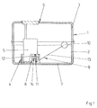
- FIG. 1 shows a plastic injection molding process manufactured fuel tank 1.
- the fuel tank 1 consists of two welded together Half shells 2, 3 together and has in its bottom area a swirl pot 4.
- the upper half-shell 3 has one for introducing a delivery unit 5 into the fuel tank 1 provided opening 6.
- the conveyor unit 5 is biased against the bottom 7 of the fuel tank 1 and sucks fuel from the swirl pot 4.
- the fuel tank 1 has a level sensor 8 with one attached to a lever arm 9 Float 10.
- the lever arm 9 is with a plastic bracket 11 attached to one on the outside of the surge pot 4
- Carrier 12 is pivotally mounted and carries with one Ironing wire 13 the float 10.
- the float 10 follows a fuel level in the fuel tank 1 and pivots the lever arm 9.
- the pivoting angle of the lever arm 9 is detected by a potentiometer 14.
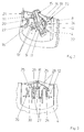
- FIG. 2 shows the components arranged on the surge pot 4 of the level sensor 8 in a greatly enlarged perspective view.
- the carrier 12 of the level sensor 8 is in one piece made with the baffle 4. In the area of storage 15 for the lever arm 9, the carrier 12 has a Distance from the surge pot 4. This allows the Plastic bracket 11 of the lever arm 9 reach behind the carrier 4.
- the fill level sensor 8 thus has a high level Stability.
- the potentiometer 14 has two on a holding part 16 of the carrier 12 arranged slideways 17. A slides on the plastic bracket over the sliding tracks 17 11 attached double contact 18.
- the level sensor 8 is not via electrical lines 19 with one shown electrical system of the motor vehicle connected.
- the electrical lines 19 are integral with the carrier 12 of the level sensor 8 manufactured clamping devices 20, 21 held. On the carrier 12 are, for example for a level switch, not shown further clamping devices 23, 24 are arranged. attacks 22 serve to limit the pivoting movement of the Plastic bracket 11. The left stop 22 with the clamping device 20 also holding the electrical lines 19.
- FIG. 3 shows the carrier 12 of the fill level sensor 8 from Figure 1 in a view from the front.
- the Carrier 12 With the Carrier 12 are guide elements 25, 26, locking hooks 27 and Spring elements 28 made in one piece.
- the leadership elements 25, 26 serve to simplify the assembly of the in Figure 2 holding part 16 shown and overlap this in the assembled position.
- the locking hook 27 secure it Holding part 16 against falling out.
- the spring elements 28 clamp the holding part 16 against in the guide elements 25, 26 and stops 29 arranged on the latching hooks 27, 30 before.
Landscapes
- Engineering & Computer Science (AREA)
- Life Sciences & Earth Sciences (AREA)
- Sustainable Development (AREA)
- Sustainable Energy (AREA)
- Chemical & Material Sciences (AREA)
- Combustion & Propulsion (AREA)
- Transportation (AREA)
- Mechanical Engineering (AREA)
- Cooling, Air Intake And Gas Exhaust, And Fuel Tank Arrangements In Propulsion Units (AREA)
- Level Indicators Using A Float (AREA)
- Details Of Rigid Or Semi-Rigid Containers (AREA)
Abstract
Description
- Fig.1
- einen Teilschnitt durch einen erfindungsgemäßen Kraftstoffbehälter,
- Fig.2
- eine perspektivische Darstellung eines Füllstandssensors des Kraftstoffbehälters aus Figur 1,
- Fig.3
- eine Ansicht auf einen Träger des Füllstandssensors aus Figur 2.
Claims (6)
- Kraftstoffbehälter für ein Kraftfahrzeug mit einem in seinem Bodenbereich angeordneten Schwalltopf und mit einem Füllstandssensor zur Ermittlung eines Füllstandes an Kraftstoff im Kraftstoffbehälter, wobei der Füllstandssensor einen auf einem Träger schwenkbar gelagerten, einen Schwimmer tragenden Hebelarm aufweist, dadurch gekennzeichnet, daß der Träger (12) einteilig mit einer Wandung des Schwalltopfes (4) oder mit einem gegen den Boden (7) des Kraftstoffbehälters (1) vorgespannten Bauteil einer Fördereinheit (5) gestaltet ist.
- Kraftstoffbehälter nach Anspruch 1, dadurch gekennzeichnet, daß eine Lagerung (15) für den Hebelarm (9) von dem Schwalltopf (4) oder dem Bauteil der Fördereinheit (5) beabstandet ist.
- Kraftstoffbehälter nach Anspruch 1 oder 2, dadurch gekennzeichnet, daß auf dem Träger (12) Klemmeinrichtungen (20, 21, 23, 24) zur Halterung von elektrischen Leitungen (19) angeordnet sind.
- Kraftstoffbehälter nach zumindest einem der vorhergehenden Ansprüche, dadurch gekennzeichnet, daß der Träger (12) Führungselemente (25, 26) zum Übergreifen eines eine Schleifbahn (17) des Potentiometers (14) tragenden Halteteils (16) aufweist.
- Kraftstoffbehälter nach zumindest einem der vorhergehenden Ansprüche, dadurch gekennzeichnet, daß das die Schleifbahn (17) tragende Halteteil (16) von einteilig mit dem Träger (12) gefertigten Federelementen (28) gegen einen Anschlag (29, 30) vorgespannt ist.
- Kraftstoffbehälter nach zumindest einem der vorhergehenden Ansprüche, dadurch gekennzeichnet, daß der Träger (12) federnde, das Halteteil (16) hintergreifende Rasthaken (27) hat.
Applications Claiming Priority (2)
| Application Number | Priority Date | Filing Date | Title |
|---|---|---|---|
| DE19842336 | 1998-09-16 | ||
| DE19842336A DE19842336C2 (de) | 1998-09-16 | 1998-09-16 | Kraftstoffbehälter für ein Kraftfahrzeug |
Publications (2)
| Publication Number | Publication Date |
|---|---|
| EP0987136A2 true EP0987136A2 (de) | 2000-03-22 |
| EP0987136A3 EP0987136A3 (de) | 2001-04-04 |
Family
ID=7881115
Family Applications (1)
| Application Number | Title | Priority Date | Filing Date |
|---|---|---|---|
| EP99116442A Ceased EP0987136A3 (de) | 1998-09-16 | 1999-08-21 | Kraftstoffbehälter für ein Kraftfahrzeug |
Country Status (3)
| Country | Link |
|---|---|
| US (1) | US6276201B1 (de) |
| EP (1) | EP0987136A3 (de) |
| DE (1) | DE19842336C2 (de) |
Cited By (3)
| Publication number | Priority date | Publication date | Assignee | Title |
|---|---|---|---|---|
| US6276201B1 (en) | 1998-09-16 | 2001-08-21 | Mannesmann Vdo Ag | Fuel tank for a motor vehicle |
| WO2005022094A1 (de) * | 2003-08-27 | 2005-03-10 | Siemens Aktiengesellschaft | Hebelgeber für einen kraftstoffbehälter |
| WO2005068946A1 (de) * | 2004-01-16 | 2005-07-28 | Siemens Aktiengesellschaft | Füllstandssensor mit einem schwimmer zur ermittlung eines füllstandes an kraftstoff in einem kraftstoffbehälter und bausatz für einen solchen füllstandssensor |
Families Citing this family (16)
| Publication number | Priority date | Publication date | Assignee | Title |
|---|---|---|---|---|
| DE19956216A1 (de) * | 1999-11-23 | 2001-05-31 | Mannesmann Vdo Ag | Zur Montage in einem Kraftstoffbehälter vorgesehenen Fördereinrichtung |
| DE10064591A1 (de) * | 2000-12-22 | 2002-06-27 | Siemens Ag | Füllstandsensor |
| JP3833513B2 (ja) * | 2001-10-22 | 2006-10-11 | ヤマハ発動機株式会社 | 自動二輪車用燃料タンクの油面検出装置 |
| DE10161403B4 (de) * | 2001-12-13 | 2007-03-29 | Siemens Ag | Kraftstofffördereinheit |
| US20030136507A1 (en) * | 2002-01-18 | 2003-07-24 | Thiel Steven A. | Thermoformed fuel tank fuel delivery system and assembly method |
| JP4112971B2 (ja) * | 2002-12-27 | 2008-07-02 | 株式会社日立製作所 | 燃料供給装置 |
| JP3941710B2 (ja) * | 2003-02-20 | 2007-07-04 | 株式会社デンソー | 液面検出装置 |
| US20050098942A1 (en) * | 2003-11-07 | 2005-05-12 | Heidelberger Druckmaschinen Ag | Pin conveyor for printed sheet material and transfer unit |
| US7261323B2 (en) * | 2005-03-31 | 2007-08-28 | Nissan Technical Center North America, Inc. | Fuel damper |
| DE102006054208B4 (de) | 2006-01-10 | 2016-04-07 | Erhard & Söhne GmbH | Behälter für Betriebsstoffe von Kraftfahrzeugen |
| DE102007021027A1 (de) * | 2007-05-04 | 2008-11-06 | Continental Automotive Gmbh | Signalgeber für einen Füllstandssensor |
| EP2646349B1 (de) | 2010-12-03 | 2015-11-04 | Salflex Polymers Ltd. | Entfaltbare kraftstofftankablenkplatte und kraftstofftanksystem |
| US8567244B2 (en) * | 2012-01-17 | 2013-10-29 | Texas, LFP, LLC | Liquid level transducer with isolated sensors |
| DE102013004931A1 (de) * | 2013-03-22 | 2014-09-25 | Kautex Textron Gmbh & Co. Kg | Verfahren zur Herstellung eines Kraftstoffbehälters sowie Kraftstoffbehälter |
| US10131223B2 (en) * | 2016-03-30 | 2018-11-20 | Honda Motor Co., Ltd. | Heat baffle clip shield |
| WO2019163654A1 (ja) * | 2018-02-22 | 2019-08-29 | 日本精機株式会社 | 液面検出装置 |
Family Cites Families (12)
| Publication number | Priority date | Publication date | Assignee | Title |
|---|---|---|---|---|
| US3756080A (en) * | 1970-05-11 | 1973-09-04 | Pringle W And Associates Inc | Fuel tank assembly |
| FR2661498B1 (fr) * | 1990-04-27 | 1992-08-07 | Jaeger | Perfectionnements aux dispositifs de mesure de niveau de carburant dans un vehicule automobile. |
| US5140303A (en) * | 1990-07-09 | 1992-08-18 | Carter Automotive Company, Inc. | Submersible electronic fuel level signal damper |
| GB2270755A (en) * | 1992-09-19 | 1994-03-23 | Ford Motor Co | A float for a liquid level operated device |
| GB2272522A (en) * | 1992-11-12 | 1994-05-18 | Ford Motor Co | A fuel tank sender assembly |
| DE4411961C2 (de) * | 1994-04-07 | 2000-07-27 | Pierburg Ag | Tankfüllstandsgeber |
| DE4433301C2 (de) * | 1994-09-19 | 1998-07-02 | Mannesmann Vdo Ag | Tankdeckel |
| DE4438322C2 (de) * | 1994-10-27 | 1998-01-15 | Pierburg Ag | Tankfüllstandsgeber |
| US5752409A (en) * | 1994-12-02 | 1998-05-19 | Delco Electronics Corporaiton | Method of accurately gauging fuel in an automotive tank |
| DE19528182B4 (de) * | 1995-08-01 | 2005-03-03 | Robert Bosch Gmbh | Kraftstoffördereinheit |
| DE19613893A1 (de) * | 1996-04-06 | 1997-10-09 | Bayerische Motoren Werke Ag | Kraftstoffbehälter für Fahrzeuge |
| DE19842336C2 (de) | 1998-09-16 | 2001-03-22 | Mannesmann Vdo Ag | Kraftstoffbehälter für ein Kraftfahrzeug |
-
1998
- 1998-09-16 DE DE19842336A patent/DE19842336C2/de not_active Expired - Fee Related
-
1999
- 1999-08-21 EP EP99116442A patent/EP0987136A3/de not_active Ceased
- 1999-09-15 US US09/396,718 patent/US6276201B1/en not_active Expired - Fee Related
Non-Patent Citations (1)
| Title |
|---|
| None |
Cited By (4)
| Publication number | Priority date | Publication date | Assignee | Title |
|---|---|---|---|---|
| US6276201B1 (en) | 1998-09-16 | 2001-08-21 | Mannesmann Vdo Ag | Fuel tank for a motor vehicle |
| WO2005022094A1 (de) * | 2003-08-27 | 2005-03-10 | Siemens Aktiengesellschaft | Hebelgeber für einen kraftstoffbehälter |
| WO2005068946A1 (de) * | 2004-01-16 | 2005-07-28 | Siemens Aktiengesellschaft | Füllstandssensor mit einem schwimmer zur ermittlung eines füllstandes an kraftstoff in einem kraftstoffbehälter und bausatz für einen solchen füllstandssensor |
| US7490514B2 (en) | 2004-01-16 | 2009-02-17 | Siemens Aktiengesellschaft | Level sensor comprising a float for determining a fuel level in a fuel tank, and kit for such a level sensor |
Also Published As
| Publication number | Publication date |
|---|---|
| DE19842336A1 (de) | 2000-03-30 |
| US6276201B1 (en) | 2001-08-21 |
| EP0987136A3 (de) | 2001-04-04 |
| DE19842336C2 (de) | 2001-03-22 |
Similar Documents
| Publication | Publication Date | Title |
|---|---|---|
| EP0987136A2 (de) | Kraftstoffbehälter für ein Kraftfahrzeug | |
| WO1999020986A1 (de) | Füllstandssensor | |
| EP1721133B1 (de) | Füllstandssensor mit einem schwimmer zur ermittlung eines füllstandes an kraftstoff in einem kraftstoffbehälter und bausatz für einen solchen füllstandssensor | |
| DE19632688B4 (de) | Befestigungseinrichtung für einen Scheinwerfer eines Kraftfahrzeuges | |
| DE19523634A1 (de) | Vorrichtung zur Aufnahme eines Kraftstofförderaggregats innerhalb eines Kraftstoffbehälters | |
| DE8807152U1 (de) | Außenspiegel für ein Fahrzeug, insbesondere für einen Lastkraftwagen | |
| DE1658999A1 (de) | Traegerflanschklammer | |
| EP1706712B1 (de) | Füllstandssensor | |
| DE19754521C2 (de) | Füllstandssensor | |
| DE19956216A1 (de) | Zur Montage in einem Kraftstoffbehälter vorgesehenen Fördereinrichtung | |
| DE10006774C2 (de) | Geformter Luftkanal mit einstückigem Halterungsbauteil | |
| EP3083312B1 (de) | Kraftstoff-sammeleinrichtung für einen kraftstoffbehälter eines kraftfahrzeuges | |
| EP1344030B1 (de) | Füllstandssensor | |
| DE69504898T2 (de) | Kraftstoffabsaug- und Anzeigevorrichtung eines Fahrzeuges | |
| DE19956143B4 (de) | Zur Montage in einem Kraftstoffbehälter vorgesehene Fördereinrichtung | |
| EP1658477A1 (de) | Hebelgeber für einen kraftstoffbehälter | |
| EP1135835B1 (de) | Hammerbürstenhalterung mit kippsicherung | |
| DE4041886C2 (de) | KFZ-Steckdose | |
| EP0658456A1 (de) | Saugstrahlpumpeneinheit | |
| DE102018208450A1 (de) | Flüssigkeitsfüllstanderfassungsvorrichtung mit Armbefestigungsabschnitt mit Halterungsnut zur Aufnahme eines Schwimmerarms | |
| DE19531732A1 (de) | Fahrpedaleinheit für Fahrzeuge | |
| DE10317809A1 (de) | Füllstandssensor für einen Kraftstoffbehälter | |
| WO2001007832A1 (de) | Leuchte mit schwenkbar gelagertem reflektorträger | |
| EP1502795A2 (de) | Fördereinheit für einen Kraftstoffbehälter | |
| EP1712397B1 (de) | Fördereinrichtung zum Fördern von Kraftstoff |
Legal Events
| Date | Code | Title | Description |
|---|---|---|---|
| PUAI | Public reference made under article 153(3) epc to a published international application that has entered the european phase |
Free format text: ORIGINAL CODE: 0009012 |
|
| AK | Designated contracting states |
Kind code of ref document: A2 Designated state(s): DE ES FR GB |
|
| AX | Request for extension of the european patent |
Free format text: AL;LT;LV;MK;RO;SI |
|
| PUAL | Search report despatched |
Free format text: ORIGINAL CODE: 0009013 |
|
| AK | Designated contracting states |
Kind code of ref document: A3 Designated state(s): AT BE CH CY DE DK ES FI FR GB GR IE IT LI LU MC NL PT SE |
|
| AX | Request for extension of the european patent |
Free format text: AL;LT;LV;MK;RO;SI |
|
| 17P | Request for examination filed |
Effective date: 20010221 |
|
| AKX | Designation fees paid |
Free format text: DE ES FR GB |
|
| RAP1 | Party data changed (applicant data changed or rights of an application transferred) |
Owner name: SIEMENS AKTIENGESELLSCHAFT |
|
| 17Q | First examination report despatched |
Effective date: 20030502 |
|
| STAA | Information on the status of an ep patent application or granted ep patent |
Free format text: STATUS: THE APPLICATION HAS BEEN REFUSED |
|
| 18R | Application refused |
Effective date: 20061230 |