EP0987129A2 - Bandages pneumatiques radiaux - Google Patents
Bandages pneumatiques radiaux Download PDFInfo
- Publication number
- EP0987129A2 EP0987129A2 EP99307359A EP99307359A EP0987129A2 EP 0987129 A2 EP0987129 A2 EP 0987129A2 EP 99307359 A EP99307359 A EP 99307359A EP 99307359 A EP99307359 A EP 99307359A EP 0987129 A2 EP0987129 A2 EP 0987129A2
- Authority
- EP
- European Patent Office
- Prior art keywords
- cord layer
- cord
- cords
- layer
- outermost
- Prior art date
- Legal status (The legal status is an assumption and is not a legal conclusion. Google has not performed a legal analysis and makes no representation as to the accuracy of the status listed.)
- Granted
Links
Images


Classifications
-
- B—PERFORMING OPERATIONS; TRANSPORTING
- B60—VEHICLES IN GENERAL
- B60C—VEHICLE TYRES; TYRE INFLATION; TYRE CHANGING; CONNECTING VALVES TO INFLATABLE ELASTIC BODIES IN GENERAL; DEVICES OR ARRANGEMENTS RELATED TO TYRES
- B60C9/00—Reinforcements or ply arrangement of pneumatic tyres
- B60C9/18—Structure or arrangement of belts or breakers, crown-reinforcing or cushioning layers
- B60C9/20—Structure or arrangement of belts or breakers, crown-reinforcing or cushioning layers built-up from rubberised plies each having all cords arranged substantially parallel
- B60C9/2003—Structure or arrangement of belts or breakers, crown-reinforcing or cushioning layers built-up from rubberised plies each having all cords arranged substantially parallel characterised by the materials of the belt cords
- B60C9/2009—Structure or arrangement of belts or breakers, crown-reinforcing or cushioning layers built-up from rubberised plies each having all cords arranged substantially parallel characterised by the materials of the belt cords comprising plies of different materials
-
- B—PERFORMING OPERATIONS; TRANSPORTING
- B60—VEHICLES IN GENERAL
- B60C—VEHICLE TYRES; TYRE INFLATION; TYRE CHANGING; CONNECTING VALVES TO INFLATABLE ELASTIC BODIES IN GENERAL; DEVICES OR ARRANGEMENTS RELATED TO TYRES
- B60C11/00—Tyre tread bands; Tread patterns; Anti-skid inserts
- B60C11/03—Tread patterns
- B60C11/0306—Patterns comprising block rows or discontinuous ribs
-
- B—PERFORMING OPERATIONS; TRANSPORTING
- B60—VEHICLES IN GENERAL
- B60C—VEHICLE TYRES; TYRE INFLATION; TYRE CHANGING; CONNECTING VALVES TO INFLATABLE ELASTIC BODIES IN GENERAL; DEVICES OR ARRANGEMENTS RELATED TO TYRES
- B60C11/00—Tyre tread bands; Tread patterns; Anti-skid inserts
- B60C11/03—Tread patterns
- B60C11/0311—Patterns comprising tread lugs arranged parallel or oblique to the axis of rotation
-
- B—PERFORMING OPERATIONS; TRANSPORTING
- B60—VEHICLES IN GENERAL
- B60C—VEHICLE TYRES; TYRE INFLATION; TYRE CHANGING; CONNECTING VALVES TO INFLATABLE ELASTIC BODIES IN GENERAL; DEVICES OR ARRANGEMENTS RELATED TO TYRES
- B60C11/00—Tyre tread bands; Tread patterns; Anti-skid inserts
- B60C11/03—Tread patterns
- B60C11/04—Tread patterns in which the raised area of the pattern consists only of continuous circumferential ribs, e.g. zig-zag
-
- B—PERFORMING OPERATIONS; TRANSPORTING
- B60—VEHICLES IN GENERAL
- B60C—VEHICLE TYRES; TYRE INFLATION; TYRE CHANGING; CONNECTING VALVES TO INFLATABLE ELASTIC BODIES IN GENERAL; DEVICES OR ARRANGEMENTS RELATED TO TYRES
- B60C9/00—Reinforcements or ply arrangement of pneumatic tyres
- B60C9/18—Structure or arrangement of belts or breakers, crown-reinforcing or cushioning layers
- B60C9/28—Structure or arrangement of belts or breakers, crown-reinforcing or cushioning layers characterised by the belt or breaker dimensions or curvature relative to carcass
-
- Y—GENERAL TAGGING OF NEW TECHNOLOGICAL DEVELOPMENTS; GENERAL TAGGING OF CROSS-SECTIONAL TECHNOLOGIES SPANNING OVER SEVERAL SECTIONS OF THE IPC; TECHNICAL SUBJECTS COVERED BY FORMER USPC CROSS-REFERENCE ART COLLECTIONS [XRACs] AND DIGESTS
- Y10—TECHNICAL SUBJECTS COVERED BY FORMER USPC
- Y10T—TECHNICAL SUBJECTS COVERED BY FORMER US CLASSIFICATION
- Y10T152/00—Resilient tires and wheels
- Y10T152/10—Tires, resilient
- Y10T152/10495—Pneumatic tire or inner tube
- Y10T152/10765—Characterized by belt or breaker structure
- Y10T152/10792—Structure where each bias angle reinforcing cord ply has no opposingly angled ply
-
- Y—GENERAL TAGGING OF NEW TECHNOLOGICAL DEVELOPMENTS; GENERAL TAGGING OF CROSS-SECTIONAL TECHNOLOGIES SPANNING OVER SEVERAL SECTIONS OF THE IPC; TECHNICAL SUBJECTS COVERED BY FORMER USPC CROSS-REFERENCE ART COLLECTIONS [XRACs] AND DIGESTS
- Y10—TECHNICAL SUBJECTS COVERED BY FORMER USPC
- Y10T—TECHNICAL SUBJECTS COVERED BY FORMER US CLASSIFICATION
- Y10T152/00—Resilient tires and wheels
- Y10T152/10—Tires, resilient
- Y10T152/10495—Pneumatic tire or inner tube
- Y10T152/10765—Characterized by belt or breaker structure
- Y10T152/1081—Breaker or belt characterized by the chemical composition or physical properties of elastomer or the like
Definitions
- This invention relates to a pneumatic radial tire, and more particularly to a heavy duty pneumatic radial tire for use in heavy vehicles such as trucks, buses and the like, which has a belt comprised of three rubberized cord layers for attaining weight reduction and improves a cut resistance in a tread portion, particularly cut resistance of a belt to enhance a durability during the running on bad road while maintaining separation resistance of the belt, cornering performance and the like at a level equal to or more than those of the conventional tire having a belt comprised of four rubberized cord layers.
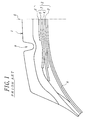
- a belt 2 in a tread portion 1 is generally comprised of four rubberized cord layers 3, 4, 5, 6, wherein cords in a first cord layer 3 located nearest to a carcass 8 are arranged at a relatively large inclination angle with respect to a plane parallel to an equatorial plane E of the tire, and cords of second cord layer 4 and third cord layer 5 are arranged so as to cross with each other with respect to the above plane to form a cross cord layer 7 composed of the second and third cord layers 4, 5, and cords in a fourth cord layer 6 are arranged in the same extending direction as the third cord layer 5 at substantially the same inclination angle as in the third cord layer 5.
- steel cords are used in each of the cord layers 3 to 6 constituting the belt 2.
- the tread portion 1 tread on sharp corner edge portion of the broken stone, small rock or the like and is occasionally subjected to cut damage reaching to the belt 2.
- the fourth cord layer 6 plays a role as a protection layer for holding the cut damage of the belt at the fourth cord layer 5 as an outermost cord layer.
- the belt occupying a greater part in the tire weight is rendered from the above four-layer structure into three-layer structure.
- cords in a first cord layer located nearest to a carcass are arranged at a relatively large inclination angle with respect to the above plane, and second cord layer and third cord layer form a cross cord layer and cords of the cross cord layer are arranged at a relatively small inclination angle with respect to the plane.
- a tire disclosed in JP-A-7-186613 has a belt comprised of three breakers (corresponding to the cord layer), wherein a tenacity of a third breaker counted from the carcass per unit width is made larger than those of first and second breakers under such a knowledge that the tenacity of the third breaker is most lacking.
- the pneumatic radial tires for use in a heavy vehicle such as truck, bus or the like are repeatedly subjected to recapping in accordance with user's demands for cost saving and resource saving. For this end, it is required to cause no fatal cut damage or cord breakage in the belt 10 and no large separation failure around the belt 10 as a tire suitable for the recapping.
- the first cord layer 3 containing cords arranged at a relatively large inclination angle is an innermost cord layer, while the inclination angle of the cord in the second to fourth cord layers 4, 5, 6 with respect to the equatorial plane E is small, so that when a top of a rib formed in a mold for the formation of a circumferential groove 9 bites into an uncured tread rubber of a tread portion in an uncured tire during the vulcanization building of the uncured tire, since the bending rigidity of a laminate of uncured cord layers is small, the bending resistance of the laminate to the entrance of the rib top of the mold is insufficient and hence the portion of the belt 20 just beneath the circumferential groove 9 indicates concave form in the resulting product tire as shown in Fig. 1.
- Such a concave form in the cord layers 5, 6 has a problem that the recapping operation is considerably degraded because the rib top is hardly peeled off from the concave form.
- the bending resistance (i.e. rigidity) of the belt as a laminate is smaller than that of the conventional tire having the belt of four-layer structure as shown in Fig. 1, and the degree of the concave form in the cord layers 12, 13 becomes larger than that of the conventional tire.
- the cut damage is stopped to an extremely small level as far as possible, and the cord breakage is hardly caused, and the separation at the end portion of the belt is stopped to a slight cracking level, and the recapping operation is good.
- these requirements are not satisfied in the conventionally proposed tires having the belt of three-layer structure at all.
- an object of the invention to provide a long-life pneumatic radial tire rendering a belt into a structure of three rubberized cord layers for holding weight reduction and improving performances required for the tire such as separation resistance of belt, cornering performance and the like at a level equal to or more than those of the conventional tire having a belt comprised of four rubberized cord layers and capable of simultaneously and largely improving cut resistance of belt as a whole of the tire including cut resistance in a circumferential groove of a tread pattern during the running on bad road and fatigue resistance of cords in an outermost cord layer constituting the belt.
- a pneumatic radial tire comprising a radial carcass comprised of at least one rubberized cord ply extending between a pair of bead cores embedded in a pair of bead portion and reinforcing a pair of sidewall portions and a tread portion, a belt reinforcing the tread portion at an outside of the carcass and comprised of three rubberized cord layers, an innermost cord layer and a middle cord layer among these cord layers being a cross cord layer that cords of the layers are crossed with each other with respect to an equatorial plane of the tire, and one or more circumferential grooves provided in at least each side region of the tread portion, characterized in that the cords of each of the innermost cord layer and the middle cord layer have an inclination angle of 10-25° with respect to the equatorial plane, and cords of an outermost cord layer have an inclination angle of 45-115° with respect to the equatorial plane as measured in the same direction
- a coating rubber for the cords of the outermost cord layer has a compression modulus of not less than 200 kgf/cm 2 .
- the resistance to buckling fatigue in the cord of the outermost cord layer is improved.
- the outermost cord layer has a width covering both widthwise ends of the middle cord layer, preferably a width corresponding to 1.0-1.2 times the width of the middle cord layer.
- a rubber gauge between the cord at an end portion of the middle cord layer and the cord of the outermost cord layer adjacent thereto is not less than 0.15 time a rubber gauge between the cord at the end portion of the middle cord layer and the cord of the innermost cord layer adjacent thereto.
- an end portion of at least one of the innermost cord layer and the middle cord layer is provided with an sheet-shaped end cover rubber enveloping such an end portion, and at least one surface of inner and outer surfaces of the cord layer end portion provided with the end cover rubber is a wavy surface forming a mountain part at a cord existing position and a valley part at a position between adjoining cords, and a difference of height between the mountain part and the valley part is within a range of 0.05-0.25 mm.
- the separation resistance at the end portion of the cross cord layer is more advantageously attained.
- At least one of the innermost cord layer and the middle cord layer is provided with a rubber layer joined to a widthwise end face of the cord layer over a full periphery of the cord layer, and the rubber layer has a width of 0.05-5.00 mm.
- a pneumatic radial tire comprising a radial carcass comprised of at least one rubberized cord ply extending between a pair of bead cores embedded in a pair of bead portion and reinforcing a pair of sidewall portions and a tread portion, a belt reinforcing the tread portion at an outside of the carcass and comprised of three rubberized cord layers, an innermost cord layer and a middle cord layer among these cord layers being a cross cord layer that cords of the layers are crossed with each other with respect to an equatorial plane, and at least two circumferential grooves provided in at least a central region of the tread portion, characterized in that the cords of each of the innermost cord layer and the middle cord layer have an inclination angle of 10-25° with respect to the equatorial plane, and cords of an outermost cord layer have an inclination angle of 45-115° with respect to the equatorial plane as measured in the same direction as in
- approved rim used herein means a standard rim (or approved rim or recommended rim) in an approved size described in a standard as mentioned later. That is, the standard is determined according to an industrial standard in an area manufacturing or using tires and defined, for example, by Year Book of The Tire and Rim Association Inc. in USA, Standard Manual of The European Tire and Rim Technical Organization in Europe, or JATMA Year Book in Japan.
- a coating rubber for the cords of the outermost cord layer has a compression modulus of not less than 200 kgf/cm 2 .
- the resistance to buckling fatigue in the cord of the outermost cord layer is improved.
- the cord layer line has a center of curvature located inward in the radial direction of the tire over a full width of the outermost cord layer.
- the cord layer line is a composite curved line, it is represented by a curvature center of the curved line.
- the cord layer line and maximum distance as mentioned above can be realized by properly selecting the inclination angle of the cord in each cord layer constituting the belt within the above defined range. They are more surely attained by using an uncured tread rubber having grooves previously formed at positions contacting with ribs of a mold for the formation of circumferential grooves in the manufacture of an uncured tire, or by approaching a ratio of an outer circumference of a belt in a cured tire to an outer circumference of a belt member in an uncured tire to 1 as far as possible, or by rendering an end count of cords in each cord layer constituting a belt of a cured tire into not less than 18 cords/50 mm.
- a pneumatic radial tire comprising a radial carcass comprised of at least one rubberized cord ply extending between a pair of bead cores embedded in a pair of bead portion and reinforcing a pair of sidewall portions and a tread portion, a belt reinforcing the tread portion at an outside of the carcass and comprised of three rubberized cord layers, an innermost cord layer and a middle cord layer among these cord layers being a cross cord layer that cords of the layers are crossed with each other with respect to an equatorial plane, and a tread portion provided with a plurality of lateral grooves extending from an inside of the tread portion toward an end thereof, characterized in that the cords of each of the innermost cord layer and the middle cord layer have an inclination angle of 10-25° with respect to the equatorial plane, and cords of an outermost cord layer have an inclination angle of 45-115° with respect to the equatorial plane
- a coating rubber for the cords of the outermost cord layer has a compression modulus of not less than 200 kgf/cm 2 .
- the resistance to buckling fatigue in the cord of the outermost cord layer is improved.
- the center line of the groove width of the lateral groove is crossed with the axial line of the cord in the outermost cord layer with respect to the plane parallel to the equatorial plane because there is an important relation between the arranging direction of the lateral groove and the cord arranging direction of the outermost cord layer.
- an end portion of at least one of the innermost cord layer and the middle cord layer is provided with an sheet-shaped end cover rubber enveloping such an end portion, and at least one surface of inner and outer surfaces of the cord layer end portion provided with the end cover rubber is a wavy surface forming a mountain part at a cord existing position and a valley part at a position between adjoining cords, and a difference of height between the mountain part and the valley part is within a range of 0.05-0.25 mm.
- the separation resistance at the end portion of the cross cord layer is more advantageously attained.
- At least one of the innermost cord layer and the middle cord layer is provided with a rubber layer joined to a widthwise end face of the cord layer over a full periphery of the cord layer, and the rubber layer has a width of 0.05-5.00 mm.
- a pneumatic radial tire comprising a radial carcass comprised of at least one rubberized cord ply extending between a pair of bead cores embedded in a pair of bead portion and reinforcing a pair of sidewall portions and a tread portion and a belt reinforcing the tread portion at an outside of the carcass and comprised of three rubberized cord layers, an innermost cord layer and a middle cord layer among these cord layers being a cross cord layer that cords of the layers are crossed with each other with respect to an equatorial plane, characterized in that the cords of each of the innermost cord layer and the middle cord layer have an inclination angle of 10-25° with respect to the equatorial plane, and cords of an outermost cord layer are high-extensible cords and have an inclination angle of 45-115° with respect to the equatorial plane as measured in the same direction as in the cords of the middle cord layer.
- a coating rubber for the cords of the outermost cord layer has a compression modulus of not less than 200 kgf/cm 2 .
- the resistance to buckling fatigue in the cord of the outermost cord layer is improved.
- the high-extensible cord has an elongation at break of not less than 4%.
- the term "high-extensible cord” used herein means a strand rope having such a structure that n filaments (n: integer) are twisted to form a strand and m strands (m: integer) are twisted together in the same direction, so-called open type cord formed by twisting 1 filaments (1: integer) each subjected to a forming so as to exceed a diameter of a cord compactly twisted together and the like.
- the value of elongation at break of the cord is determined by dividing displacement at break when the cord taken out from the tire is pulled by means of an Instron tension testing machine by a distance between chucks before the pulling.
- an end portion of at least one of the innermost cord layer and the middle cord layer is provided with an sheet-shaped end cover rubber enveloping such an end portion, and at least one surface of inner and outer surfaces of the cord layer end portion provided with the end cover rubber is a wavy surface forming a mountain part at a cord existing position and a valley part at a position between adjoining cords, and a difference of height between the mountain part and the valley part is within a range of 0.05-0.25 mm.
- the separation resistance at the end portion of the cross cord layer is more advantageously attained.
- At least one of the innermost cord layer and the middle cord layer is provided with a rubber layer joined to a widthwise end face of the cord layer over a full periphery of the cord layer, and the rubber layer has a width of 0.05-5.00 mm.
- a pneumatic radial tire comprising a radial carcass comprised of at least one rubberized cord ply extending between a pair of bead cores embedded in a pair of bead portion and reinforcing a pair of sidewall portions and a tread portion, a belt reinforcing the tread portion at an outside of the carcass and comprised of three rubberized cord layers, an innermost cord layer and a middle cord layer among these cord layers being a cross cord layer that cords of the layers are crossed with each other with respect to an equatorial plane, and a pair of circumferential shoulder grooves formed on at least both side regions of the tread portion, characterized in that the cords of each of the innermost cord layer and the middle cord layer have an inclination angle of 10-25° with respect to the equatorial plane, and cords of an outermost cord layer are high-extensible cords and have an inclination angle of 45-115° with respect to the equa
- a coating rubber for the cords of the outermost cord layer has a compression modulus of not less than 200 kgf/cm 2 .
- the resistance to buckling fatigue in the cord of the outermost cord layer is improved.
- two circumferential central grooves extending so as to sandwich the equatorial plane of the tire therebetween are arranged in a central region of the tread portion and the width of the outermost cord layer is wider than a width between groove edges of the circumferential central grooves farthest from the equatorial plane.
- the cross cord layer indicates a lamination structure of adjoining cord layers that the cords of these cord layers are arranged in different directions with respect to the equatorial plane of the tire (upward to the right and upward to the left).
- steel cords are favorably used in the cord ply of the carcass and each cord layer of the belt.
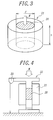
- the compression modulus of the coating rubber is used a value calculated according to the following method. That is, a rubber specimen 20 is closely filled in a metal jig 21 or a steel jig having a columnar hollow portion with a diameter d of 14 mm and a height h of 28 mm as shown in Fig. 3, and then the jig 21 is set in a compression testing machine 22 as shown in Fig. 4. Thereafter, a load W is applied to upper and lower faces of the rubber specimen 20 at a rate of 0.6 mm/min, during which a displacement of the rubber specimen 20 is measured by means of a laser displacement meter 23. Then, the compression modulus is calculated from a relation of the measured displacement to the load W.
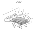
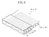
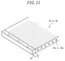
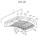
- a first embodiment of the heavy duty pneumatic radial tire according to the invention comprises a pair of bead portions (not shown), a pair of sidewall portions (not shown) and a tread portion 31 extending between the pair of the sidewall portions and provided on its ground contact side with a tread rubber 32.
- the tire 30 comprises a radial carcass 33 extending between a pair of bead cores (not shown) embedded in the bead portions to reinforce the pair of the bead portions and the pair of the sidewall portions and the tread portion and comprised of one or more rubberized cord plies, one cord ply in the illustrated embodiment and a belt 34 arranged on an outer circumference of the carcass 33 to reinforce the tread portion 31.
- the belt 34 is comprised of three rubberized cord layers 35, 36, 37, wherein cords 35a, 36a of each of an innermost cord layer 35 nearest to the carcass 33 and a middle cord layer 36 are crossed with each other with respect to an equatorial plane E of the tire and the innermost cord layer 35 and the middle cord layer 36 form a cross cord layer 38.
- the cords 35a of the innermost cord layer 35 and the cords 36a of the middle cord layer 36 are arranged at an inclination angle ( ⁇ , ⁇ ) of 10-25°, preferably 15-22° with respect to the equatorial plane E, respectively.
- cords 37a of an outermost cord layer 37 are arranged at an inclination angle ( ⁇ ) of 45-115°, preferably 50-100° with respect to the equatorial plane E as measured in the same direction as the inclination angle ⁇ of the cord 36a of the middle cord layer 36. And also, the cord 37a in the outermost cord layer 37 is covered with a coating rubber having a compression modulus of not less than 200 kgf/cm 2 .
- the central region of the tread portion 31 is provided with rows of blocks 44, 45, 46 defined by four circumferential grooves 39, 40 extending straightforward in the circumferential direction and a plurality of lateral grooves 41, 42, 43 extending between the mutual circumferential grooves 39, 39 and between the circumferential grooves 39 and 40 and opening to the respective circumferential grooves, which grooves being formed on the tread rubber 32, and each of both side regions of the tread portion is provided with a row of blocks 48 defined by the circumferential groove 40 and a plurality of lateral grooves 47 opening thereto.
- the tread pattern shown in Fig. 2 is a block pattern of forming the blocks over a full region of the tread portion 31, the invention may take a rib pattern wherein ribs are formed over the full region of the tread portion only by plural circumferential grooves or a block-rib pattern of combining rib rows and block rows in the tread portion.
- the circumferential grooves 39, 40 in the illustrated embodiment are straight grooves, but may be zigzag grooves.
- the outermost cord layer 37 has a width extending toward an end of the tread portion 31 over an outermost groove edge of an outermost circumferential groove among the circumferential grooves located in both side regions of the tread portion, the circumferential groove 40 in the illustrated embodiment in a widthwise direction of the tread portion.
- a width Lb 1 of the outermost cord layer 37 is larger than a distance Lg between planes P 1 , P 2 parallel to the equatorial plane E passing through the outermost groove edges of the circumferential grooves 40 located at both side regions of the tread portion.
- the width end 37E of the outermost cord layer 37 always locates outward from the plane P 1 , P 2 in the widthwise direction of the tire.
- the cords 35a of the innermost cord layer 35 and the cords 36a of the middle cord layer 36 are arranged at the inclination angle ( ⁇ , ⁇ ) of 10-25°, preferably 15-22° with respect to the equatorial plane E, while the cords 37a of the outermost cord layer 37 are arranged at the inclination angle ( ⁇ ) of 45-115°, preferably 50-100° with respect to the equatorial plane E as measured in the same direction as in the cord 36a of the middle cord layer 36, whereby circumferential tension created in the belt 34 of the tread portion 31 when the tire 30 is inflated under an inner pressure as shown by an arrow Fx in Fig.
- the belt 34 tends to project outward in the radial direction of the tire 30 by tension Fx created in the belt 34 when the tire 30 is inflated under the inner pressure and hence the belt 34 intends to contract inward in the widthwise direction thereof as a whole, so that the cords 35a, 36a and 37a of the cord layers 35, 36, 37 in the belt 34 are intended to change into a direction of decreasing the inclination angles ⁇ , ⁇ , ⁇ , respectively.
- the inclination angle y of the cord 37a of the outermost cord layer 37 is considerably larger than those ⁇ , ⁇ of the cords 35a, 36a of the innermost cord layer 35 and the middle cord layer 36, so that the degree of decreasing the inclination angle in the cord 37a is very small as compared with those of the cords 35a, 36a and hence the outermost cord layer 37 indicates a tendency hardly causing the contraction in the widthwise direction.
- the outermost cord layer 37 acts to control the contraction of the cross cord layer 38 in the widthwise direction because the cords 37a of the outermost cord layer 37 acts as a prop to the cross cord layer 38.
- the cross cord layer 38 having the controlled widthwise contraction increases the circumferential rigidity of the tread portion 31, and hence the cornering power (hereinafter abbreviated as CP) can be improved even in the tire 30 having the belt 34 of the three-layer structure to develop the cornering performance equal to or more than that of the conventional tire having a belt of four-layer structure.
- the increase of the circumferential rigidity in the cross cord layer 38 largely contributes to control the growth of tire size in the inflation of the tire under the inner pressure.
- the inclination angles ⁇ , ⁇ of the cords 35a and 36a in the innermost cord layer 35 and the middle cord layer 36 are approximately equal to each other with respect to the equatorial plane E and the planes P 1 , P 2 parallel to the equatorial plane from a viewpoint that tension is equally born by the cords 35a and 36a.
- Fig. 7 is shown a comparison of CP property between the tire 30 having the belt 34 and the conventional tire having the belt of four-layer structure.
- the CP property of the tire 30 is measured by changing the inclination angle ⁇ of the cord 37a of the outermost cord layer 37 and represented by an index on the basis that the conventional tire is 100.
- the adequate inclination angle y indicating the index value of not less than 100 i.e. CP property is equal to or more than that of the conventional tire
- the CP property is degraded as compared with that of the conventional tire, so that the inclination angle ⁇ should be within the adequate range of 45-115°. From this fact, it is proved that the cords 37a of the outermost cord layer 37 act as a prop to the widthwise contraction of the cross cord layer 38 and enhance the circumferential rigidity of the cross cord layer 38.
- the outermost cord layer 37 in the belt 34 is forcedly subjected to a bending deformation at a large curvature and hence a large compression force is locally applied to the outermost cord layer 37 to cause buckling in the cords 37a thereof.
- rubber having a compression modulus of not less than 200 kgf/cm 2 is used as a coating rubber 37b for the cord 37a in the outermost cord layer 37, whereby the compression resistance of the coating rubber 37b is increased, so that it is possible to prevent the buckling deformation of the cord 37a in the outermost cord layer 37.
- the cord 37a of the outermost cord layer 37 receiving the cut input of the sharp corner edge of the foreign matter is slight in the tension bearing ratio and has a sufficient energy against the cut, so that the entrance of the corner edge can be stopped by the outermost cord layer 37 to prevent the breakage of the cords 36a in the middle cord layer 36.
- the outermost cord layer 37 is required to have a width extending outward over the outermost groove edge of the outermost circumferential groove 40 in the widthwise direction of the tire. If the circumferential groove 40 is a zigzag groove, the outermost cord layer 37 is sufficient to have a width extending outward over a top of the groove edge at the outermost position of the mountain-shaped groove in the widthwise direction.
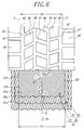
- the width of the outermost cord layer 37 (developed width Lb 1 ) is enough to be narrower than a width of the middle cord layer 36 as shown in Fig. 6.
- the width of the outermost cord layer 37 (developed width Lb 2 ) in the belt 34 is made wider than the width of the middle cord layer 36 (developed width Lc) so as to cover both widthwise ends of the middle cord layer 37 with the outermost cord layer 37.
- the width of the outermost cord layer 37 is favorable to be within a range of 1.0-1.2 times the width of the middle cord layer 36.
- the width of the outermost cord layer 37 becomes wider, tensile strain at the end portion of the outermost cord layer 37 just beneath the tire under loading in the rotating axial direction of the tire increases, and if the width of the outermost cord layer 37 exceeds 1.2 times the width of the middle cord layer 36, the tensile strain at the end portion of the outermost cord layer 37 becomes excessively large and hence the separation failure is apt to be caused at the end of the outermost cord layer 37.
- the shearing strain between the end portion of the middle cord layer 36 and the outermost cord layer 37 naturally increases as compared with the case that the width of the outermost cord layer 37 is less than the width of the middle cord layer 36.
- a sheet-shaped end cover rubber 49 is arranged in a widthwise end portion of at least one of the innermost cord layer 35 and the middle cord layer 36 so as to cover the end portion of the cord layer.
- At least one surface of inner surface 50a and outer surface 50b in the radial direction of the tire at the end portion of the innermost cord layer 35 or the middle cord layer 36 provided with the end cover rubber 49, the inner and outer surfaces 50a, 50b in the illustrated embodiment are a wavy surface forming a mountain part at a cord existing position (35a, 36a) and a valley part at a position between adjoining cords (35a, 36a) of the layer.
- the surface 51 of the end cover rubber 49 has a wavy surface consisting of mountain parts 51a and valley parts 51b.
- the mountain part 51a corresponds to the cord existing position 52 (35a, 36a) and the valley part 51b corresponds to the position 53 between the adjoining cords (35a, 36a).
- a difference of height H between the mountain part 51a and the valley part 51b is within a range of 0.05-0.25 mm. Such a height difference H largely contributes to control the occurrence of separation between the innermost cord layer 35 and the end portion of the middle cord layer 36 constituting the cross cord layer 38.
- the reason why the height difference H between the mountain part 51a and the valley part 51b in the end cover rubber 49 is restricted to a range of 0.05-0.25 mm is due to the fact that when the height difference H is less than 0.05 mm, the effect of controlling the occurrence of separation at the end portion of the cross cord layer 38 is not obtained in practice, while when it exceeds 0.25 mm, a greater amount of air is enveloped in recess portions corresponding to valley parts 51b of the tire 30 during the laying of cord layer members for the belt in the building of an uncured tire and a portion enveloping air is not adhered in the vulcanization building of the uncured tire and hence separation is caused from such a portion.
- the wavy form on the inner surface 50a and the outer surface 50b of the innermost cord layer 35 or the middle cord layer 36 and the surface 51 of the end cover rubber 49 is carried out by a method wherein at least one surface of at least an end portion of an uncured rubberized cord layer member cut into a given length is pushed by the same roll as comb roll aligning steel cords in a given arranging direction when a continuous cord layer member corresponding to cord layers 35, 36 for the cross cord layer 38 of the belt 34 is manufactured by calendar rolls, or by thinning rubber gauge of uncured coating rubber for the cords 35a, 36a.
- the rubber gauge is set considering the fact that if the rubber gauge of the coating rubber is too thin, the cords 35a, 36a are easily exposed at the production stage of uncured members.
- a rubber layer 54 is joined to a widthwise end face of at least one of the innermost cord layer 35 and the middle cord layer 36 over a full periphery of the cord layer instead of the end cover rubber 49.
- the rubber layer 54 can prevent the projection of ends of the cords 35a, 36a of the innermost cord layer 35 and the middle cord layer 36 into the tread rubber 32 and contributes to improve the separation resistance at the end portion of the cross cord layer 38.
- the width a of the rubber layer 54 is within a range of 0.05-5.00 mm.
- the width a of the rubber layer 54 is less than 0.05 mm, the effect of controlling the occurrence of separation failure becomes too small, while when the width a exceeds 5.00 mm, if the uncured cord layer members for the innermost cord layer 35 and the middle cord layer 36 are fed onto a building drum from their feeding devices in the building of the uncured tire, the uncured rubber member for the rubber layer 54 hangs down or turn up and there is caused a problem of damaging the operability.
- the end cover rubber 49 may not be arranged, but the rubber layer 54 and the end cover rubber 49 may be used together. In the latter case, the surface 51 of the end cover rubber 49 is not necessarily rendered into the wavy surface 51a, 51b.
- the rubber layer 54 is favorable to have the same rubber composition as coating rubbers for the cord in the innermost cord layer 35 and the cord in the middle cord layer 36 from a viewpoint of the productivity.
- the ends of the cords 35a of the innermost cord layer 35 and the cords 36a of the middle cord layer 36 can be protected by the rubber layer 54 having the same rubber composition, which is advantageous in the improvement of the separation resistance.
- the end cover rubber 49 is favorable to have a 100% modulus larger than that of the cord coating rubber.
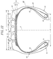
- Fig. 12 a second embodiment of the pneumatic radial tire according to the invention.
- This tire 60 comprises a pair of bead portions 61, a pair of sidewall portions 62 and a tread portion 63 connecting to both sidewall portions 62 to each other.
- the tire 60 comprises a radial carcass 65 extending between a pair of bead cores 64 embedded in the bead portions 61 to reinforce the pair of the bead portions 61 and the pair of the sidewall portions 62 and the tread portion 63 and comprised of one or more rubberized steel cord plies, one cord ply in the illustrated embodiment and a belt 66 arranged on an outer circumference of the carcass 65 to reinforce the tread portion 63.
- the belt 66 is comprised of three rubberized steel cord layers 67, 68, 69, wherein innermost cord layer 67 and middle cord layer 68 form a cross cord layer 70. Further, the tire 60 has a tread rubber 71 in the tread portion 63 located on an outer peripheral side of an outermost cord layer 69, and at least a central region Rc of the tread rubber 71 in the tread portion 63 is provided with at least two circumferential grooves extending in the circumferential direction of the tread portion 63 as a pair.
- the tread portion 63 of the illustrated embodiment is provided on its central region Rc with two circumferential grooves 75 (hereinafter referred to as circumferential center groove 75) and on each of both side regions Rs with one circumferential groove 76 (hereinafter referred to as circumferential shoulder groove 76).
- the central region Rc is a region corresponding to 1/2 of a width W of a tread surface 63t of the tread portion 63, which is two equal parts sandwiching an equatorial plane E of the tire when the width W of the tread surface is divided into four equal parts or 1/4W parts, and each of both side regions Rs is a region corresponding to 1/4W part.
- the width W is a distance between intersect points each being an intersect between an extended line of the tread surface 63t and an extended line of buttress.
- circumferential center groove 65 and circumferential shoulder groove 66 may be straight groove, straight groove having see-through protrusions therein, curved groove having arcs on both groove edges wherein the arc has a large radius of curvature and centers of the radii of curvature of the arcs are alternately changed into inside and outside of the groove in the widthwise direction of the tread surface 63t, or a zigzag groove having a relatively small amplitude.
- cords 67a of the innermost cord layer 67 nearest to the carcass 65 and cords 68a of the middle cord layer 68 are arranged so as to cross with each other with respect to the equatorial plane E of the tire.
- the inclination angles ⁇ , ⁇ of the cord 67a of the innermost cord layer 67 and the cord 68a of the middle cord layer 68 with respect to the equatorial plane E of the tire are within a range of 10-25°, preferably 15-22°, respectively.
- the cords 69a of the outermost cord layer 69 have an inclination angle ⁇ of 45-115°, preferably 50-100° with respect to the equatorial plane E as measured in the same direction as the cords 68a of the middle cord layer 68.
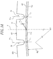
- a cord layer line C 69 passing through a center of a thickness of the outermost cord layer 69 is comprised of a curved line or a composite of curved line and straight line.
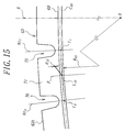
- the cord layer line C 69 shown in Figs. 14 and 15 is a curved line, which is an arc having a radius of curvature R 69 .
- a center O of the radius of curvature is existent inside the tire over a full width of the outermost cord layer 69.
- the middle cord layer 68 may have the same cord layer line C 68 (not shown) as the cord layer line C 69 . Moreover, when the cord layer line C 69 (including the line C 68 ) is a composite of curved line and straight line, a portion of the straight line locates just beneath each of the circumferential center groove 65 and the circumferential shoulder groove 66.
- a line segment L 12 connecting two intersects I 1 , I 2 of lines V C1 , V C2 equally dividing a groove width of the circumferential center groove 65 to the cord layer line C 69 is existent inside the cord layer line C 69 in the radial direction of the tire or is consistent therewith.
- a maximum distance d 12 between the line segment L 12 and the cord layer line C 69 is not more than 1.0 mm, desirably not more than 0.7 mm.
- a position of a line indicating the maximum distance d 12 is substantially consistent with a middle position between the pair of the circumferential center grooves 75 or the equatorial plane E.
- a line segment L 13 connecting an intersect I 3 between a line V C3 equally dividing a groove width of the circumferential shoulder groove 76 and the cord layer line C 69 to the intersect I 1 is existent inside the cord layer line C 69 in the radial direction of the tire or is consistent therewith.
- a maximum distance d 13 between the line segment L 13 and the cord layer line C 69 is not more than 1 mm, desirably not more than 0.7 mm.
- a position of a line F indicating the maximum distance d 13 is substantially consistent with a middle position between the circumferential center groove 75 and the circumferential shoulder groove 76.
- the peeling operation of the outermost cord layer 69 is unfavorably degraded in the recapping.
- the lower limit of the maximum distance d is zero.
- the radius of curvature R 69 is shown as a radius of curvature in the cord layer line C 69 , plural radii of curvature may be existent in the cord layer line C 69 .
- the above is true in the middle cord layer 68.
- the cords 67a of the innermost cord layer 67 and the cords 68a of the middle cord layer 68 are arranged at the inclination angle ( ⁇ , ⁇ ) of 10-25°, preferably 15-22° with respect to the equatorial plane E, while the cords 69a of the outermost cord layer 69 are arranged at the inclination angle ( ⁇ ) of 45-115°, preferably 50-100° with respect to the equatorial plane E as measured in the same direction as in the cord 68a of the middle cord layer 68, whereby circumferential tension created in the belt 66 of the tread portion 63 when the tire 60 is inflated under an inner pressure as shown by an arrow Fx in Fig.
- the tread portion 63 of the tire 60 during the running under loading rides on a foreign matter such as broken stone, small rock or the like having a sharp corner edge
- the cords 69a of the outermost cord layer 69 are less in the tension bearing and have an energy enough to counter to the cut, so that they are hardly cut and hence the ability of stopping the entrance of the corner edge of the foreign matter by the outermost cord layer 69 becomes considerably higher and the cutting of the cords 68a in the middle cord layer 68 hardly occurs and consequently the durability of the tire 60 is improved based on such a cut resistance.
- the belt 66 tends to project outward in the radial direction of the tire 60 by tension Fx created in the belt 66 when the tire 60 is inflated under the inner pressure and hence the belt 66 intends to contract inward in the widthwise direction thereof as a whole, so that the cords 67a, 68a and 69a of the cord layers 67, 68, 69 in the belt 66 are intended to change into a direction of decreasing the inclination angles ⁇ , ⁇ , ⁇ , respectively.
- the inclination angle ⁇ of the cord 69a of the outermost cord layer 69 is considerably larger than those ⁇ , ⁇ of the cords 67a, 68a of the innermost cord layer 67 and the middle cord layer 68, so that the degree of decreasing the inclination angle in the cord 69a is very small as compared with those of the cords 67a, 68a and hence the outermost cord layer 69 indicates a tendency hardly causing the contraction in the widthwise direction.
- the outermost cord layer 69 acts to control the contraction of the cross cord layer 70 in the widthwise direction because the cords 69a of the outermost cord layer 69 acts as a prop to the cross cord layer 70.
- the cross cord layer 70 having the controlled widthwise contraction increases the circumferential rigidity of the tread portion 63, and hence the cornering power (CP) can be improved even in the tire 60 having the belt 66 of the three-layer structure to develop the cornering performance equal to or more than that of the conventional tire having a belt of four-layer structure.
- the increase of the circumferential rigidity in the cross cord layer 70 largely contributes to control the growth of tire size in the inflation of the tire under the inner pressure, which largely contributes to improve the separation resistance at the end portion of the belt 66, particularly the end portion of the cross cord layer 70.
- the inclination angles ⁇ , ⁇ of the cords 67a and 68a in the innermost cord layer 67 and the middle cord layer 68 are approximately equal to each other with respect to the equatorial plane E from a viewpoint that tension is equally born by the cords 67a and 68a.
- the adequate inclination angle y indicating the index value of not less than 100 is within a range of 45-115°.
- the inclination angle ⁇ is less than 45° or exceeds 115°, the CP property is degraded as compared with that of the conventional tire, so that the inclination angle ⁇ should be within the adequate range of 45-115°. From this fact, it is proved that the cords 69a of the outermost cord layer 69 act as a prop to the widthwise contraction of the cross cord layer 70 and enhance the circumferential rigidity of the cross cord layer 70.
- the section shape of at least the outermost cord layer 69 is set so that the curved lien or the composite of curved line and straight line in the cord layer line C 69 of the outermost cord layer 69 (see Figs. 14 and 15) including the cord layer line C 68 of the middle cord layer 68 has a center O of the radius of curvature inside the tire over the full width of the outermost cord layer 69, the peeling of the outermost cord layer 69 subjected to cut damage is very easy in the recapping after the use of the tire and the recapping operation is largely improved.
- the above cord layer line C 68 , C 69 can be attained by restricting the inclination angle y of the cord 69a of the outermost cord layer 69 to a range of 45-115° with respect to the equatorial plane. Because, when the top of the mold rib for the formation of the circumferential groove 75, 76 bites into an uncured tread rubber in a tread portion of an uncured tire under the action of high pressure gas filled in the inside of the uncured tire during the vulcanization building of the uncured tire, the uncured cord layer as the outermost cord layer 69 increases the bending rigidity in the widthwise direction because the inclination angle is an angle near to a range of 45-115° and hence the bending resistance of the laminate as the belt is increased against the entrance of the top of the mold rib.
- the uncured tread rubber having grooves previously formed at positions corresponding to the mold ribs for the formation of the circumferential center grooves 75 and circumferential shoulder grooves 76 is used to decrease pushing force of the mold ribs against the uncured cord layers constituting the belt 66, or a ratio of outer periphery (outer diameter) of the uncured cord layer in the uncured tire to outer periphery (outer diameter) of the outermost cord layer 69 in the cured tire is approached to 1 as far as possible, whereby the change of peripheral length of the uncured cord layer in the vulcanization building can be controlled to a minimum to make the cord layer line C 68 , C 69 more sufficient.
- the end count of each cord layer in the belt is rendered into not less than 18 cords/50 mm, whereby the cords are densely arranged in each of the cord layers, which also contributes to the construction of the cord layer line.
- a coating rubber 69b for the cord 69a of the outermost cord layer 69 has a compression modulus of not less than 200 kgf/cm 2 likewise the aforementioned first embodiment.
- the uncured rubber for rubber having a compression modulus of not less than 200 kgf/cm 2 is high in minimum value of Mooney viscosity, so that it contributes to increase the bending rigidity of the laminate of uncured cord layers for the belt 66 against the mold rib in the vulcanization building of the uncured tire.
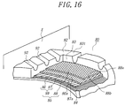
- a third embodiment of the pneumatic radial tire according to the invention comprises a pair of bead portions (not shown), a pair of sidewall portions (not shown) and a tread portion 82 connecting to both sidewall portions to each other.
- the tire 80 comprises a radial carcass 84 extending between a pair of bead cores (not shown) embedded in the bead portions to reinforce the pair of the bead portions, the pair of the sidewall portions and the tread portion 82 and comprised of one or more rubberized cord plies, one cord ply in the illustrated embodiment and a belt 85 arranged on an outer circumference of the carcass 84 to reinforce the tread portion 82.
- the belt 85 is comprised of three rubberized steel cord layers 86, 87, 88, wherein cords 86a and 87a of innermost cord layer 86 located nearest to the carcass 84 and middle cord layer 87 are arranged so as to be crossed with each other with respect to an equatorial plane E of the tire to thereby form a cross cord layer 89.
- inclination angles ⁇ , ⁇ of the cords 86a and 87a in the innermost cord layer 86 and the middle cord layer 87 are within a range of 10-25°, preferably 15-22° with respect to the equatorial plane, respectively.
- cords 88a of an outermost cord layer 88 are arranged at an inclination angle ⁇ of 45-115°, preferably 50-100° with respect to the equatorial plane E as measured in the same direction as the inclination angle ⁇ of the cord 87a of the middle cord layer 87. And also, the cord 88a in the outermost cord layer 88 is covered with a coating rubber 88b having a compression modulus of not less than 200 kgf/cm 2 .
- the central region of the tread portion 82 and a region located in the vicinity thereof are provided with rows of blocks 95, 96, 97 defined by four circumferential grooves 90, 91 extending straightforward in the circumferential direction and a plurality of lateral grooves 92, 93, 94 extending between the mutual circumferential grooves 90, 90 and between the circumferential grooves 90 and 91 and opening to the respective circumferential grooves, which grooves being formed on the tread rubber 83, and each of both side regions of the tread portion is provided with a row of blocks 99 defined by the circumferential groove 91 and a plurality of lateral grooves 99 opening thereto.
- the tread pattern shown in Fig. 17 is a block pattern of forming the blocks over a full region of the tread portion 82
- the invention may take a pattern that the rows of the blocks defined by the circumferential grooves and the lateral grooves are provided on at least the central region of the tread portion and another land portion such as rib or the like is formed in each of both side regions.
- an inclination angle 6 of a center line 92L of a groove width of the lateral groove 92 with respect to the equatorial plane E has an inclination angle difference of not less than 20° with respect to an axial line of the cord 88a in the outermost cord layer 88 having the above inclination angle ⁇ with respect to the equatorial plane.
- inclination angles ⁇ 1 , ⁇ 2 of center lines 93L, 94L of groove widths of the lateral grooves 93, 94 with respect to planes P 3 , P 4 parallel to the equatorial plane E have an inclination angle difference of not less than 20° with respect to the axial line of the cord 98a in the outermost cord layer 98 having the above inclination angle ⁇ with respect to the equatorial plane, respectively.
- Such a relation of the inclination angle difference is applied to the lateral grooves 98 defining the blocks 99 of a block row located at each of both side regions of the tread portion 82 in the circumferential direction.
- the feature that the inclination angles ⁇ , ⁇ 1 , ⁇ 2 have the inclination angle difference of not less than 20° with respect to the axial line of the cord 88a of the outermost cord layer 88 means that when ⁇ >6, ⁇ > ⁇ 1 and ⁇ > ⁇ 2 are existent as regards the inclination angle ⁇ of the cord 88a, there are ⁇ - ⁇ 20°, ⁇ - ⁇ 1 ⁇ 20° and ⁇ - ⁇ 2 ⁇ 20°, and when ⁇ , ⁇ 1 and ⁇ 2 are existent, there are ⁇ - ⁇ 20°, ⁇ 1 - ⁇ 20° and ⁇ 2 - ⁇ 20°.
- the cords 86a of the innermost cord layer 86 and the cords 87a of the middle cord layer 87 are arranged at the inclination angle ( ⁇ , ⁇ ) of 10-25°, preferably 15-22° with respect to the equatorial plane E, while the cords 89a of the outermost cord layer 89 are arranged at the inclination angle ( ⁇ ) of 45-115°, preferably 50-100° with respect to the equatorial plane E as measured in the same direction as in the cord 88a of the middle cord layer 88, whereby circumferential tension created in the belt 85 of the tread portion 82 when the tire 80 is inflated under an inner pressure as shown by an arrow Fx in Fig.
- the belt 85 tends to project outward in the radial direction of the tire 80 by tension Fx created in the belt 85 when the tire 80 is inflated under the inner pressure and hence the belt 85 intends to contract inward in the widthwise direction thereof as a whole, so that the cords 86a, 87a and 88a of the cord layers 86, 87, 88 in the belt 85 are intended to change into a direction of decreasing the inclination angles ⁇ , ⁇ , ⁇ , respectively.
- the inclination angle ⁇ of the cord 88a of the outermost cord layer 88 is considerably larger than those ⁇ , ⁇ of the cords 86a, 87a of the innermost cord layer 86 and the middle cord layer 87, so that the degree of decreasing the inclination angle in the cord 88a is very small as compared with those of the cords 86a, 87a and hence the outermost cord layer 88 indicates a tendency hardly causing the contraction in the widthwise direction.
- the outermost cord layer 88 acts to control the contraction of the cross cord layer 89 in the widthwise direction because the cords 88a of the outermost cord layer 88 acts as a prop to the cross cord layer 89.
- the cross cord layer 89 having the controlled widthwise contraction increases the circumferential rigidity of the tread portion 82, and hence the cornering power (CP) can be improved even in the tire 80 having the belt 85 of the three-layer structure to develop the cornering performance equal to or more than that of the conventional tire having a belt of four-layer structure.
- the increase of the circumferential rigidity in the cross cord layer 89 largely contributes to control the growth of tire size in the inflation of the tire under the inner pressure, which largely contributes to the improvement of the separation resistance at the end portion of the belt 85, particularly the end portion of the cross cord layer 89.
- the inclination angles ⁇ , ⁇ of the cords 86a and 87a in the innermost cord layer 86 and the middle cord layer 87 are approximately equal to each other with respect to the equatorial plane E from a viewpoint that tension is equally born by the cords 86a and 87a.
- the adequate inclination angle y indicating the index value of not less than 100 is within a range of 45-115°.
- the inclination angle ⁇ is less than 45° or exceeds 115°, the CP property is degraded as compared with that of the conventional tire, so that the inclination angle y should be within the adequate range of 45-115°. From this fact, it is proved that the cords 88a of the outermost cord layer 88 act as a prop to the widthwise contraction of the cross cord layer 89 and enhance the circumferential rigidity of the cross cord layer 89.
- the outermost cord layer 88 in the belt 85 is forcedly subjected to a bending deformation at a large curvature and hence a large compression force is locally applied to the outermost cord layer 88 to cause buckling in the cords 88a thereof.
- rubber having a compression modulus of not less than 200 kgf/cm 2 is used as a coating rubber 88b for the cord 88a in the outermost cord layer 88, whereby the compression resistance of the coating rubber 88b is increased, so that it is possible to prevent the buckling deformation of the cord 88a in the outermost cord layer 88.
- the compression modulus of the coating rubber is less than 200 kgf/cm 2 . the above effect is insufficient.
- the sharp corner edge of the foreign matter such as broken stone or rock scatted on the road surface bites into the bottom of the lateral grooves 92, 93, 94 so as to extend the longitudinal direction of the corner edge along the lateral grooves 92, 93, 94 during the running of the tire
- the extending directions of the lateral grooves 92, 93, 94 are consistent with the extending direction of the cord 88a of the outermost cord layer 88 or slightly differ therefrom
- the corner edge of the foreign matter arrives at the outermost cord layer 88 in the belt 85 through the thin tread rubber 83 located just beneath the bottoms of these grooves and further easily passes through the outermost cord layer 88 to cut the cords 87a of the middle cord layer 87 bearing a large tension and having a less energy against cut input. Because, the cord 88a to be durable to the cut input is hardly existent in the outermost cord layer 88 or the number of the cords 88a is very little.
- the lines 92L, 93L, 94L passing through groove centers of the lateral grooves 92, 93, 94 are crossed with the axial line of the cord 88a of the outermost cord layer 88 with respect to the equatorial plane E and planes P 3 , P 4 parallel thereto.
- the circumferential grooves 90 and 91 are not necessarily required.
- a tire having a lug pattern may be formed by connecting a portion of the lateral groove 92 located toward an end of the tread portion 82 to the lateral grooves 93 and 98, and connecting a portion of the lateral groove 92 located toward an end of the tread portion 82 to the lateral grooves 94 and 98, respectively.
- a sheet-shaped end cover rubber 100 is arranged in a widthwise end portion of at least one of the innermost cord layer 86 and the middle cord layer 87 so as to cover the end portion of the cord layer.
- At least one surface of inner surface 101a and outer surface 101b in the radial direction of the tire at the end portion of the innermost cord layer 86 or the middle cord layer 87 provided with the end cover rubber 100, the inner and outer surfaces 101a, 102b in the illustrated embodiment are a wavy surface forming a mountain part at a cord existing position (86a, 87a) and a valley part at a position between adjoining cords (86a, 87a) of the layer.
- the surface 102 of the end cover rubber 100 has a wavy surface consisting of mountain parts 102a and valley parts 102b.
- the mountain part 102a corresponds to the cord existing position 103 (86a, 87a) and the valley part 102b corresponds to the position 104 between the adjoining cords (86a, 87a).
- a difference of height H between the mountain part 102a and the valley part 102b is within a range of 0.05-0.25 mm.
- Such a height difference H largely contributes to control the occurrence of separation between the innermost cord layer 85 and the end portion of the middle cord layer 86 constituting the cross cord layer 89.
- the reason why the height difference H between the mountain part 102a and the valley part 102b in the end cover rubber 100 is restricted to a range of 0.05-0.25 mm is due to the fact that when the height difference H is less than 0.05 mm, the effect of controlling the occurrence of separation at the end portion of the cross cord layer 89 is not obtained in practice, while when it exceeds 0.25 mm, a greater amount of air is enveloped in recess portions corresponding to valley parts 102b of the tire 80 during the laying of cord layer members for the belt in the building of an uncured tire and a portion enveloping air is not adhered in the vulcanization building of the uncured tire and hence separation is caused from such a portion.
- the wavy form on the inner surface 101a and the outer surface 101b of the innermost cord layer 86 or the middle cord layer 87 and the surface 102 of the end cover rubber 100 is carried out by a method wherein at least one surface of at least an end portion of an uncured rubberized cord layer member cut into a given length is pushed by the same roll as comb roll aligning steel cords in a given arranging direction when a continuous cord layer member corresponding to cord layers 86, 87 for the cross cord layer 89 of the belt 85 is manufactured by calendar rolls, or by thinning rubber gauge of uncured coating rubber for the cords 86a, 87a.
- the rubber gauge is set considering the fact that if the rubber gauge of the coating rubber is too thin, the cords 86a, 87a are easily exposed at the production stage of uncured members.
- a rubber layer 105 is joined to a widthwise end face of at least one of the innermost cord layer 86 and the middle cord layer 87 over a full periphery of the cord layer instead of the end cover rubber 100.
- the rubber layer 105 can prevent the projection of ends of the cords 86a, 87a of the innermost cord layer 86 and the middle cord layer 87 into the tread rubber 83 and contributes to improve the separation resistance at the end portion of the cross cord layer 89.
- the width a of the rubber layer 105 is within a range of 0.05-5.00 mm.
- the width a of the rubber layer 105 is less than 0.05 mm, the effect of controlling the occurrence of separation failure becomes too small, while when the width a exceeds 5.00 mm, if the uncured cord layer members for the innermost cord layer 86 and the middle cord layer 87 are fed onto a building drum from their feeding devices in the building of the uncured tire, the uncured rubber member for the rubber layer 105 hangs down or turn up and there is caused a problem of damaging the operability.
- the end cover rubber 100 may not be arranged, but the rubber layer 105 and the end cover rubber 100 may be used together. In the latter case, the surface 102 of the end cover rubber 100 is not necessarily rendered into the wavy surface 102a, 102b.
- the rubber layer 105 is favorable to have the same rubber composition as coating rubbers for the cord in the innermost cord layer 86 and the cord in the middle cord layer 87 from a viewpoint of the productivity.
- the ends of the cords 86a of the innermost cord layer 86 and the cords 87a of the middle cord layer 87 can be protected by the rubber layer 105 having the same rubber composition, which is advantageous in the improvement of the separation resistance.
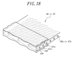
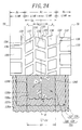
- Figs. 21 and 22 is shown a fourth embodiment of the pneumatic radial tire according to the invention.
- Numeral 110 is a heavy duty pneumatic radial tire, numeral 112 a radial carcass, numeral 103 a crown portion of the carcass, numeral 114 a tread portion, numeral 105 a belt comprised of cord layers 116 to 118 and numeral 119 a cross cord layer.
- the belt 115 reinforcing the tread portion 114 is arranged on an outer periphery of the crown portion 113 of the radial carcass 112 toroidally extending between a pair of bead cores (not shown) embedded in a pair of bead portions (not shown).
- the belt 115 is comprised of three rubberized cord layers 116, 117, 118, wherein cords 116a, 117a of each of an innermost cord layer 116 and a middle cord layer 117 are crossed with each other with respect to an equatorial plane E of the tire and the innermost cord layer 116 and the middle cord layer 117 form a cross cord layer 119.
- cords 116a of the innermost cord layer 116 and the cords 117a of the middle cord layer 117 are arranged at an inclination angle of 10-25° with respect to the equatorial plane E, respectively.
- cords 118a of an outermost cord layer 118 are high-extensible cords, preferably high-extensible cords having an elongation at break of not less than 4% and are arranged at an inclination angle of 45-115°, preferably 50-100° with respect to the equatorial plane E as measured in the same direction as the inclination angle of the cord 117a of the middle cord layer 117.
- the cord 118a in the outermost cord layer 118 is covered with a coating rubber 118b having a compression modulus of not less than 200 kgf/cm 2 .
- the cords 116a of the innermost cord layer 116 and the cords 117a of the middle cord layer 117 are arranged at the inclination angle of 10-25°, preferably 15-22° with respect to the equatorial plane E, while the cords 118a of the outermost cord layer 118 are arranged at the inclination angle of 45-115° with respect to the equatorial plane E, whereby a force Fx acting to the circumferential direction of the tire created when the tire is inflated under an inner pressure as shown in Fig.
- the cord breakage is hardly caused by using the high-extensible cord as the cord of the outermost cord layer, so that the end count of the outermost cord layer can be decreased, whereby the weight reduction can be attained.
- the inclination angle of the cord 118a of the outermost cord layer 118 is considerably larger than those of the cords 116a, 117a of the innermost cord layer 116 and the middle cord layer 117, so that the change of the inclination angle in the cord 118a is very small and hardly contracts in the widthwise direction, so that the outermost cord layer 118 can not follow to the contracting deformation of the cord layers 116, 117 in the widthwise direction.
- the outermost cord layer 118 acts to control the contraction of the cord layers 116, 117 in the widthwise direction (so-called prop action), whereby the rigidity of the cord layers 116, 117 in the circumferential direction is increased to increase the cornering power (CP) and to control the growth of the tire size in the inflation under the inner pressure.
- the inclination angles of the cords 116a and 117a in the innermost cord layer 116 and the middle cord layer 117 are approximately equal to each other with respect to the equatorial plane E from a viewpoint that tension is equally born by the cords 116a and 117a.
- the reason why the inclination angles of the cords 116a and 117a are restricted to a range of 10-25° is due to the fact that when the inclination angle is less than the lower limit, interlaminar shearing strain produced at the end portions of the cord layers 116, 117 becomes too large and the separation failure is apt to be caused between the cord layers 116 and 117 (in the cross cord layer), while when it exceeds the upper limit, the cords 116a, 117a can not sufficiently counter to the tension acting to the circumferential direction of the tire.
- the adequate inclination angle of the cord 118a of the outermost cord layer 118 indicating the index value of not less than 100 is within a range of 45-115°.
- the tire has the cornering power equal to or more than that of the conventional tire. This is considered to be due to the fact that the cords 118a of the outermost cord layer 118 develops a sufficient prop action to enhance the rigidity of the cross cord layer in the circumferential direction.
- a coating rubber 118b having a compression modulus of not less than 200 kgf/cm 2 is used in the cords 118a of the outermost cord layer 118.
- the buckling hardly occurs even at a state as shown in Fig. 2 and the breakage of the cord 118a in the outermost cord layer 118 can sufficiently be controlled. Consequently, the durability which is apt to be lacking when the belt is comprised of three cord layers for attaining the weight reduction can be enhanced to a level equal to that of the conventional tire having the belt of four cord layers.
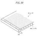
- a fifth embodiment of the pneumatic radial tire according to the invention comprises a pair of bead portions (not shown), a pair of sidewall portions (not shown) and a tread portion 122 extending between the pair of the sidewall portions and provided on its ground contact side with a tread rubber 123.
- the tire 120 comprises a radial carcass 124 extending between a pair of bead cores (not shown) embedded in the bead portions to reinforce the pair of the bead portions and the pair of the sidewall portions and the tread portion and comprised of one or more rubberized cord plies, one cord ply in the illustrated embodiment and a belt 125 arranged on an outer circumference of the carcass 124 to reinforce the tread portion 122.
- the belt 125 is comprised of three rubberized steel cord layers 126, 127, 128, wherein cords 126a, 127a of each of an innermost cord layer 126 nearest to the carcass 124 and a middle cord layer 127 are crossed with each other with respect to an equatorial plane E of the tire and the innermost cord layer 126 and the middle cord layer 127 form a cross cord layer 129.
- the cords 126a of the innermost cord layer 126 and the cords 127a of the middle cord layer 127 are arranged at an inclination angle ( ⁇ , ⁇ ) of 10-25°, preferably 15-22° with respect to the equatorial plane E, respectively.
- cords 128a of an outermost cord layer 128 are arranged at an inclination angle ( ⁇ ) of 45-115°, preferably 50-100° with respect to the equatorial plane E as measured in the same direction as the inclination angle ⁇ of the cord 127a of the middle cord layer 127. And also, the cord 128a in the outermost cord layer 128 is covered with a coating rubber 128b having a compression modulus of not less than 200 kgf/cm 2 .
- the tread portion 122 of this tire 120 shown in Fig. 24 has a block pattern formed in the tread rubber 123 over a full region thereof.
- one or more circumferential shoulder grooves, one circumferential shoulder groove 130 extending straightforward in the circumferential direction in the illustrated embodiment is provided at least on each of both side regions Rs.
- straight circumferential center grooves 121 located on both sides of the equatorial plane E are arranged in a central region Rc of the tread portion 122.
- the central region Rc is a region sandwiching the equatorial plane E from both sides with a width of 1/4W
- the both side regions Rs are regions located at the both sides of the central region with a width of 1/4W.
- the central region Rc of the tread portion 122 is provided with rows of blocks 135, 136, 137 defined by a plurality of lateral grooves 132 extending between the mutual circumferential center grooves 131, 131 and opening to the respective grooves 131 and a plurality of lateral grooves 133, 134 extending between the mutual circumferential shoulder groove 130 and circumferential center groove 131 and opening to the respective grooves 130, 131, while each of both side regions Rs of the tread portion is provided with a row of blocks 139 defined by the circumferential shoulder groove 130 and a plurality of lateral grooves 138 opening thereto.
- tread pattern there may be taken a rib pattern wherein land portions such as ribs and the like are formed over the full region of the tread portion or a block-rib pattern of combining rib rows and block rows in the tread portion.
- the circumferential grooves 130, 131 in the illustrated embodiment are straight grooves, but may be zigzag grooves.
- the outermost cord layer 128 has a width Lb narrower than a distance between groove edges of the circumferential shoulder grooves nearest to the equatorial plane among the circumferential shoulder grooves arranged in the both side regions Rs of the tread portion 122 as a pair, between the groove edges of the circumferential shoulder grooves 130 nearest to the equatorial plane E in the illustrated embodiment, i.e. the width Lb is narrower than a developed width Lg 1 in Fig. 24.
- a widthwise end 128E of the outermost cord layer 128 is located between the equatorial plane E and a groove edge position nearest to the equatorial plane E in both groove edges of the circumferential shoulder groove 130 nearest to the equatorial plane E.
- the width Lb of the outermost cord layer 128 is wider than a distance between mutual groove edges of the circumferential center grooves 131 located in the central region Rc and farthest from the equatorial plane E, i.e. the width Lb is wider than a developed width Lg 2 in Fig. 24.
- the widthwise end 128E of the outermost cord layer 128 is located between the groove edge of the circumferential shoulder groove 130 nearest to the equatorial plane E and the groove edge of the circumferential center groove 131 farthest from the equatorial plane E.
- the cords 126a of the innermost cord layer 126 and the cords 127a of the middle cord layer 127 are arranged at the inclination angle ( ⁇ , ⁇ ) of 10-25°, preferably 15-22° with respect to the equatorial plane E, while the cords 128a of the outermost cord layer 128 are arranged at the inclination angle ( ⁇ ) of 45-115°, preferably 50-100° with respect to the equatorial plane E as measured in the same direction as in the cord 127a of the middle cord layer 127, whereby circumferential tension created in the belt 125 of the tread portion 122 when the tire 120 is inflated under an inner pressure as shown by an arrow Fx in Fig.
- the tread portion 122 of the tire 120 during the running under loading rides on a foreign matter such as broken stone, small rock or the like having a sharp corner edge, even if the corner edge arrives at the belt 125 through the tread rubber 123, the cords 128a of the outermost cord layer 128 are hardly cut and the durability of the tire 120 is improved based on such a cut resistance.
- the belt 125 tends to project outward in the radial direction of the tire 120 by tension Fx created in the belt 125 when the tire 120 is inflated under the inner pressure and hence the belt 125 intends to contract inward in the widthwise direction thereof as a whole, so that the cords 126a, 127a and 128a of the cord layers 126, 127, 128 in the belt 125 are intended to change into a direction of decreasing the inclination angles ⁇ , ⁇ , ⁇ , respectively.
- the inclination angle ⁇ of the cord 128a of the outermost cord layer 128 is considerably larger than those ⁇ , ⁇ of the cords 126a, 127a of the innermost cord layer 126 and the middle cord layer 127, so that the degree of decreasing the inclination angle in the cord 128a is very small as compared with those of the cords 126a, 127a and hence the outermost cord layer 128 indicates a tendency hardly causing the contraction in the widthwise direction.
- the outermost cord layer 128 acts to control the contraction of the cross cord layer 129 in the widthwise direction because the cords 128a of the outermost cord layer 128 acts as a prop to the cross cord layer 129.
- the cross cord layer 129 having the controlled widthwise contraction increases the circumferential rigidity of the tread portion 129, and hence the cornering power (CP) can be improved even in the tire 120 having the belt 125 of the three-layer structure to develop the cornering performance equal to or more than that of the conventional tire having a belt of four-layer structure.
- the increase of the circumferential rigidity in the cross cord layer 129 largely contributes to control the growth of tire size in the inflation of the tire under the inner pressure.
- the inclination angles ⁇ , ⁇ of the cords 126a and 127a in the innermost cord layer 126 and the middle cord layer 127 are approximately equal to each other with respect to the equatorial plane E and the planes P 5 , P 6 parallel to the equatorial plane from a viewpoint that tension is equally born by the cords 126a and 127a.
- the adequate inclination angle ⁇ indicating the index value of not less than 100 is within a range of 45-115°.
- the inclination angle ⁇ is less than 45° or exceeds 115°, the CP property is degraded as compared with that of the conventional tire, so that the inclination angle ⁇ should be within the adequate range of 45-115°. From this fact, it is proved that the cords 128a of the outermost cord layer 128 act as a prop to the widthwise contraction of the cross cord layer 129 and enhance the circumferential rigidity of the cross cord layer 129.
- the occurrence of the cut damage can be more reduced by making the width of the outermost cord layer 128 narrower than the distance between the groove edges of the mutual circumferential shoulder grooves 130 nearest to the equatorial plane E, and there is actually no belt trouble based on the cut damage.
- the weight reduction of the tire can be attained when the width of the outermost cord layer 128 is made narrower than the width of the conventional outermost cord layer as mentioned above.
- the width of the outermost cord layer is made wider than the distance between the groove edges of the mutual circumferential center grooves 131 farthest from the equatorial plane E, whereby the outermost cord layer 128 can be served as a cut protection layer for the middle cored layer 127 and innermost cord layer 126 against cut applied to the bottom of the circumferential center groove 131 in the central region Rc frequently subjected to the cut damage and hence the sufficient cut resistance of the belt 125 is guaranteed.
- the circumferential center groove 131 is a zigzag groove
- the difference between inclination angle of the zigzag groove with respect to the plane P 5 , P 6 parallel to the equatorial plane E and inclination angle of the cord 128a of the outermost cord layer 128 is favorably rendered into not less than 20° as measured in the same direction as the cord 127a of the middle cord layer 127. If such an inclination angle difference is less than 20°, the number of the cords 128a receiving the entrance of the corner edge of the foreign matter becomes too small.
- the width of the outermost cord layer 128 is adaptable to be within a range of 25-70% of a width of the middle cord layer 127. Because, it is necessary that the middle cord layer 127 gives the rigidity required in the tread portion 122 to the tire 120 together with the innermost cord layer 126 and hence the middle cord layer 127 is required to have a width approximately equal to a width of a tread surface 123t of the tread portion 122 (see Fig. 23).
- the cord 128a of the outermost cord layer 128 receiving the cut input of the sharp corner edge of the foreign matter is slight in the tension bearing ratio and has a sufficient energy against the cut, so that the entrance of the corner edge can be stopped by the outermost cord layer 128 to prevent the breakage of the cords 127a in the middle cord layer 127.
- the outermost cord layer 128 is required to have a width extending outward over the distance between the outermost groove edges of the circumferential center grooves 131 in the widthwise direction of the tire.
- the outermost cord layer 128 is sufficient to have a width extending outward over a top of the outermost groove edge at the outermost position of the mountain-shaped groove in the widthwise direction of the tire.
- the outermost cord layer 128 in the belt 125 is forcedly subjected to a bending deformation at a large curvature and hence a large compression force is locally applied to the outermost cord layer 128 to cause buckling in the cords 128a thereof.
- rubber having a compression modulus of not less than 200 kgf/cm 2 is used as a coating rubber 128b for the cord 128a in the outermost cord layer 128, whereby the compression resistance of the coating rubber 128b is increased, so that it is possible to prevent the buckling deformation of the cord 128a in the outermost cord layer 128.
- the compression modulus of the coating rubber is less than 200 kgf/cm 2 . the above effect is insufficient.
- radial tires for truck and bus to be tested having a tire size of 11R22.5 and a structure as shown in Figs. 5, 6 and 8-11, wherein a belt 34 has a three-layer structure comprised of innermost cord layer 35, middle cord layer 36 and outermost cord layer 37 provided that the innermost cord layer 35 and the middle cord layer 36 form a cross cord layer 38. All cords 35a, 36a, 37a of the cord layers 35, 36, 37 are made of steel cords of 1 ⁇ 0.34+6 ⁇ 0.34 and an end count in each cord layer is 18.0 cords/50 mm.
- the number of cord layers in the belt 34, cord inclination angle in each cord layer ( ⁇ , ⁇ , ⁇ ) and compression modulus (kgf/cm 2 ) of coating rubber for the cord 37a of the outermost cord layer 37 are shown in Table 1.
- the inclination angles ⁇ , ⁇ , ⁇ (°) are represented in Table 1 as a cord inclination angle of a cord layer attached by 1B, 2B, 3B, 4B (not existing in the examples) from a carcass 33 in this order.
- symbol R attached before the value of the inclination angle means that the cords are arranged upward to the right
- symbol L means that the cords are arranged upward to the left.
- the carcass 33 is comprised of one rubberized radial carcass ply containing steel cords of (3+9+15) ⁇ 0.175.
- the other construction of the tire is according to the custom.
- a tire of the conventional example having the same structure as in the above example except that the belt is comprised of four cord layers as shown in Fig. 1, and tires of Comparative Examples 1-6 wherein at least one of the inclination angles of the cord layers in the belt and the compression modulus of the coating rubber 37b for the outermost cord layer 37 is outside the range defined in the invention.
- the test tire rendered into so-called stone bitten state by biting a steel filler having a tip with an angle of 90° into a block 44 nearest to the equatorial plane E of the tire is inflated under an inner pressure of 7.5 kgf/cm 2 and run under a load of 2750 kgf/tire over a distance of 10,000 km. Thereafter, the tire is dissected to examine the cord cut breakage of the outermost cord layer. The durability is evaluated by the presence or absence of cord cut breakage.
- the test tire inflated under an inner pressure of 7.5 kgf/cm 2 is run on the drum under a load of 2750 kgf over a distance of 10,000 km so as to locate the semi-sphere to substantially a center of the tread portion. Thereafter, the tire is dissected to examine cord breakage in the outermost cord layer. The durability is evaluated by the presence or absence of cord breakage.
- the test tire inflated under an inner pressure of 7.5 kgf /cm 2 is run under a load of 2750 kgf at a state of applying a lateral force of 0.3 g (gravity acceleration) over a distance of 1,000 km. Thereafter, the tire is dissected to measure crack length produced at the end of the middle cord layer.
- the belt durability is evaluated by a reciprocal of the crack length and represented by an index on the basis that the control tire is 100, wherein the larger the index value, the better the property.
- the test tire mounted onto a rim (rim size: 8.25) is run on a drum testing machine under conditions that the inner pressure is 7.5 kgf/cm 2 and the load is 2750 kgf, during which a slip angle is increased every 1° within a range of 1-4° and CP is calculated from cornering force measured at each of the slip angles.
- the cornering property is evaluated by an average value of CP and represented by an index on the basis that the conventional tire is 100, wherein the larger the index value, the better the property.
- the tires of Examples 1-14 maintain sound state without causing the cut breakage or cord breakage in the cords 37a of the outermost cord layer 37 in the tests A and B, and have the durability and CP property equal to or more than those of the conventional tire in the tests C and D.
- the tires of Comparative Examples 1-6 are poor in at least one of the cord breakage or cord cut breakage of the outermost cord layer and the cornering property as compared with the conventional tire.
- tires of Examples 15-18 having the same tire size and structure as in Example 1 and a tread pattern shown in Fig. 6 wherein a distance between outermost groove edges of straight circumferential grooves 40 arranged in both side regions of the tread portion 31 in widthwise direction (distance Lg in Fig. 6) is 100 mm.
- a distance between outermost groove edges of straight circumferential grooves 40 arranged in both side regions of the tread portion 31 in widthwise direction is 100 mm.
- the same conventional tire as used in Example 1 and tires of Comparative Examples 7 and 8 having the same structure as in Example 1 except that the width of the outermost cord layer is outside the range defined in the invention.
- the cord inclination angles and widths of cord layers 1B-4B are shown in Table 2.
- the cut resistance at the bottom of the outermost circumferential groove 40 is measured with respect to these tires by the following test method to obtain results as shown in Table 2.
- the cut resistance of the belt 34 at the bottom of the circumferential groove 40 is evaluated by a cut energy of DxF/2 and represented by an index on the basis that the conventional tire is 100, wherein the larger the index value, the better the property.
- Conventional Example 4 R52 R18 L18 L18 150 180 150 80 100 Comparative Example 7 3 R18 L18 L52 - 180 150 90 - 92 Comparative Example 8 3 R18 L18 L52 - 180 150 100 - 94
- tires of Examples 19-20 having the same tire size as in Example 1 and a tread pattern as shown in Fig. 8.
- the same conventional tire as used in Example 1 and tires of Comparative Examples 9-11 having the same structure as in Example 19 except that at least one of a ratio of rubber gauge G 23 (mm) between steel cord at an end of middle cord layer 36 and steel cord of outermost cord layer 37 adjacent thereto to rubber gauge G 12 (mm) between steel cord at an end of middle cord layer 36 and steel cord of innermost cord layer 35 adjacent thereto and width of outermost cord layer 37 is varied.
- cord inclination angles and widths of cord layers 1B-4B and ratio of width W 37 of outermost cord layer 37 to width W 36 of middle cord layer 36 are shown in Table 3.
- Example 3 The same Test C as described in Example 1 is carried out with respect to the tires of Examples 19-20, conventional tire and tires of Comparative Examples 9-11 to measure crack length from each end of the middle cord layer 36 and outermost cord layer 37.
- the belt durability is evaluated by a reciprocal of the measured crack length and represented by an index on the basis that the crack length inside the end of the cord layer 3B in the conventional tire is 100 wherein the larger the index value, the better the property.
- the measured results are shown in Table 3.
- the word “inside” means inside in the radial direction of the tire
- the word “outside” means outside in the radial direction of the tire.
- the results of cord layer 3B is shown in the term 2B
- the result of cord layer 4B is shown in the term 3B.
- Example 2 Furthermore, the same Test C as in Example 1 is continued until the occurrence of separation failure in the belt.
- the belt durability or separation resistance is directly evaluated by the running time until the occurrence of troubles and represented by an index on the basis that the running time of the conventional tire is 100 wherein the larger the index value, the better the property.
- the measured results are shown in Table 3.
- the position of trouble in the belt is also shown in Table 3.
- the tire of Comparative Example 9 in which the width of the outermost cord layer is narrower by 20 mm than the width of the middle cord layer is long in the crack length produced from the end of the middle cord layer and causes the separation failure at a relatively premature time based on the growth of such a crack
- the tire of Comparative Example 10 in which the width of the outermost cord layer is wider by 40 mm than the width of the middle cord layer is long in the crack length produced from the end of the outermost cord layer and causes the separation failure at a relatively premature time based on the growth of such a crack.
- the running time until the occurrence of trouble is equal to or slightly higher than that of the conventional tire.
- the tire of Comparative Example 11 in which the rubber gauge ratio G 23 /G 12 is too small even if the widths of the outermost cord layer and middle cord layer are rationalized is long in the crack length from the outside end of the middle cord layer and the running time thereof is slightly higher than that of the conventional tire.
- the cracks from the ends of the middle cord layer and outermost cord layer are shorter than those of the conventional tire and hence the running time until the occurrence of trouble is considerably longer than that of the conventional tire, which attain a level recognizing the significance in market.
- radial tires for truck and bus of Examples 21-24 having a tire size of 11R22.5 and a structure as shown in Figs. 12 to 15, wherein a tread portion 63 is provided with a pair of circumferential center grooves 75 and a pair of circumferential shoulder grooves 76 and a belt 66 is comprised of innermost cord layer 67, middle cord layer 68 and outermost cord layer 69 provided that the innermost cord layer 67 and middle cord layer 68 form a cross cord layer 70.
- All of cords 67a, 68a, 69a in the cord layers 67, 68, 69 are steel cords of 1x0.34+6x0.34 and an end count of each cord layer is 18.0 cords/50 mm and a compression modulus of a coating rubber for steel cord in the innermost cord layer and middle cord layer is 170 kgf/cm 2 .
- cord inclination angles ⁇ , ⁇ , ⁇ (°) in the cord layers 67, 68, 69 of the belt 66 and a compression modulus of a coating rubber 69b for steel cord in the outermost cord layer 69 are shown in Table 4.
- a maximum distance d12 (mm) between line segment L12 and cord layer line C69 and a maximum distance d13 (mm) between line segment L13 and cord layer line C69 are measured, a larger value among the measured values is shown as maximum distance d (mm) in Table 4.
- the inclination angles ⁇ , ⁇ , ⁇ (°) are represented in Table 4 as a cord inclination angle of a cord layer attached by 1B, 2B, 3B, 4B (not existing in the examples and comparative examples) from a carcass 65 in this order.
- symbol R attached before the value of the inclination angle means that the cords are arranged upward to the right
- symbol L means that the cords are arranged upward to the left.
- the carcass 65 is one rubberized radial ply containing steel cords of (3+9+15) ⁇ 0.175 therein.
- each of these tires is mounted onto a truck and actually run on bad road over a distance of 50,000 km and thereafter taken out from the truck. Then, the remaining tread rubber is cut out from the tire to expose the outermost cord layer of the belt and then the peeling operation of the outermost cord layer is first evaluated and thereafter cut damage and cord breakage state of the peeled outermost cord layer are examined and the presence or absence of cut damage in the middle cord layer is observed.
- the results are also shown in Table 4. Particularly, the peeling operability is evaluated by difficulty of the peeling and bad influence to the middle cord layer and represented by an index on the basis that the conventional tire is 100 wherein the larger the index value, the better the property.
- the tires of Examples 21-24 are excellent in the cut resistance of the belt, resistance to cord breakage in the outermost cord layer and peeling operability of the cord layer as compared with the conventional tire and the tires of Comparative Examples 12-13. Furthermore, the tires of Examples 21-24 are excellent in the resistance to cord breakage and the peeing operability as compared with the tire of Comparative Example 14. Moreover, the tires of Examples 21-24 are considerably excellent in the peeling operability as compared with the tire of Comparative Example 15.
- the tires of Examples 21-24 are tires having not only the excellent durability on bad road but also the excellent recappability inclusive of the peeling operability.
- radial tires for truck and bus of Examples 25-38 having a tire size of 11R22.5 and a structure as shown in Figs. 16-20, wherein a belt 85 is comprised of innermost cord layer 86, middle cord layer 87 and outermost cord layer 88 provided that the innermost cord layer 86 and the middle cord layer 87 form a cross cord layer 89. All of cords 86a, 87a, 88a of the cord layers 86, 87, 88 are steel cords of 1 ⁇ 0.34+6 ⁇ 0.34 and an end count in each cord layer is 18.0 cords/50 mm.
- the number of cord layers in the belt, cord inclination angles ⁇ , ⁇ , ⁇ (°) of the cord layers and compression modulus of a coating rubber 88b for the outermost cord layer 88 are shown in Table 5.
- the inclination angles ⁇ , ⁇ , ⁇ (°) are represented in Table 5 as a cord inclination angle of a cord layer attached by 1B, 2B, 3B, 4B (not existing in the examples) from a carcass 84 in this order.
- symbol R attached before the value of the inclination angle means that the cords are arranged upward to the right
- symbol L means that the cords are arranged upward to the left.
- the carcass 84 is one rubberized radial ply containing steel cords of (3+9+15) ⁇ 0.175 therein.
- the other construction of the tire is according to the custom.
- the conventional tire having the same structure as in the above example except that the belt is comprised of four cord layers as shown in Fig. 1, and tires of Comparative Examples 16-21 wherein at least one of the inclination angles of the cord layers in the belt and the compression modulus of the coating rubber 88b for the outermost cord layer 88 is outside the range defined in the invention.
- the tires of Examples 25-38 maintain sound state without causing the cut breakage or cord breakage in the cords 88a of the outermost cord layer 88 in the tests A and B, and have the durability and CP property equal to or more than those of the conventional tire in the tests C and D.
- the tires of Comparative Examples 16-21 are poor in at least one of the cord breakage or cord cut breakage of the outermost cord layer and the cornering property as compared with the conventional tire.
- tires of Examples 39-41 having the same tire size and structure as in Example 25 and a tread pattern shown in Fig. 17 wherein an inclination angle ⁇ (°) of a line 92L passing through a width center of a lateral groove 92 formed in a tread rubber 83 of a tread portion 82 with respect to an equatorial plane E of the tire is varied.
- ⁇ (°) of a line 92L passing through a width center of a lateral groove 92 formed in a tread rubber 83 of a tread portion 82 with respect to an equatorial plane E of the tire is varied.
- the same conventional tire as used in Example 25 and tires of Comparative Examples 22-24 having the same structure as in Example 25 except that the inclination angle 6 (°) in the lateral groove 92 is outside the range defined in the invention.
- cord inclination angles ⁇ , ⁇ , ⁇ (°) of cord layers 1B-4b, inclination angle ⁇ (°) of lateral groove 92 in a row of blocks 95 and inclination angle difference between inclination angle y of cord 88a in the outermost cord layer 88 and inclination angle 6 of lateral groove 92 are shown in Table 6.
- the tires of Examples 39-41 have the cut resistance of the belt 85 at the bottom of the lateral groove 92 equal to or more than that of the conventional tire having the belt of four-layer structure, while the tires of Comparative Examples 22-24 largely degrade the cut resistance of the belt 85 at the bottom of the lateral groove 92 as compared with the conventional tire.
- pneumatic radial tires of Examples 42-55 having a tire size of 11R22.5 and a structure as shown in Figs. 21 and 22, wherein a belt 115 is comprised of three cord layers 116-118.
- cords 116a and 117a of innermost cord layer 116 and middle cord layer 117 are steel cords of (1+6) ⁇ 0.34 and an end count of each cord layer is 18.0 cords/50 mm.
- An elongation at break of each of these cords 116a and 117a is 2.5%.
- cords 118a of an outermost cord layer 118 are high-extensible strand ropes each having a cord structure of 4 ⁇ 4 ⁇ 0.23 obtained by twisting 4 steel filaments to form a strand and twisting four strands in the same direction, and an end count of this layer is 14.7 cords/50 mm. An elongation at break of the rope is 3.0%.
- the number of cord layers in the belt, cord inclination angles (°) in the belt and a compression modulus of a coating rubber 118b for the outermost cord layer 118 are shown in Table 7.
- a carcass 112 is comprised of one rubberized radial ply containing steel cords of (3+9+15) ⁇ 0.175.
- the other structure of the tire is the same as in the usual pneumatic radial tire for truck and bus.
- the conventional tire having a belt of four-layer structure as shown in Fig. 1, and tires of Comparative Examples 25-30 wherein at least one of the cord inclination angles in the belt and the compression modulus of the coating rubber for the outermost cord layer is outside the range defined in the invention.
- all cords used in the belt are steel cords of (1+6) ⁇ 0.34 having an elongation at break of 2.5% and an end count of each cord layer is 18.0 cords/50 mm.
- the tires of Examples 42-55 maintain a sound state without causing the cut breakage or cord breakage in the cords of the outermost cord layer 88 in the tests A and B, and have the durability and CP property equal to or more than those of the conventional tire in the tests C and D.
- the tires of Comparative Examples 25-30 are poor in at least one of the cord breakage or cord cut breakage of the outermost cord layer and the cornering property as compared with the conventional tire.
- radial tires of Examples 56-61 having the same structure as in Example 42 except that as the cord 118a of the outermost cord layer 118 are used high-extensible cords having an elongation at break of 3.5%, 4.0%, 4.5%, 5.0%, 5.5% or 6.0% by changing at least one of cord structure and twisting pitch as shown in Table 8.
- the belt durability is evaluated by measuring the cut energy indicating the easiness of cord breakage in the same manner as described in Example 15 to obtain results as shown in Table 8 together with the results of the conventional example and Example 42.
- Example 42 4 ⁇ 4 ⁇ 0.23 14.7 3.0 103
- Example 56 4 ⁇ 4 ⁇ 0.23 14.7 3.5
- Example 57 4 ⁇ 4 ⁇ 0.23 14.7 4.0
- Example 58 4 ⁇ 4 ⁇ 0.23 14.7 4.5
- Example 60 3 ⁇ 7 ⁇ 0.23 11.2 5.5
- Example 61 3 ⁇ 7 ⁇ 0.23 11.2 6.0 128
- radial tires for truck and bus of Examples 62-65 having a tire size of 11R22.5 and a structure as shown in Figs. 23 and 24 wherein a tread portion 122 is provided with a pair of circumferential shoulder grooves 130 and a pair of circumferential center grooves 131 and a distance between groove edges of the circumferential shoulder grooves 130 corresponding to a developed width Lg 1 shown in Fig. 24 is 100 mm and a distance between groove edges of the circumferential center grooves 131 corresponding to a developed width Lg 2 shown in Fig. 24 is 35 mm.
- a belt 125 has a three-layer structure comprised of innermost cord layer 126, middle cord layer 127 and outermost cord layer 128 provided that the innermost cord layer 126 and the middle cord layer 127 form a cross cord layer 129. All cords 126a, 127a, 128a of the cord layers 126, 127, 128 are made of steel cords of 1 ⁇ 0.34+6 ⁇ 0.34 and an end count in each cord layer is 18.0 cords/50 mm.
- a compression modulus of a coating rubber 128b for the outermost cord layer 128 is 350 kgf/cm 2 and a compression modulus of a coating rubber for the innermost cord layer 126 and middle cord layer 127 is 170 kgf/cm 2 .
- the cord inclination angles ⁇ , ⁇ , ⁇ (°) and widths (mm) of the cord layers 126, 127 and 128 in the belt 125 are shown in Table 9.
- the inclination angles ⁇ , ⁇ , ⁇ (°) are represented in Table 9 as a cord inclination angle of a cord layer attached by 1B, 2B, 3B, 4B (not existing in the examples) from a carcass 124 in this order.
- symbol R attached before the value of the inclination angle means that the cords are arranged upward to the right
- symbol L means that the cords are arranged upward to the left.
- the carcass 124 is comprised of one rubberized radial carcass ply containing steel cords of (3+9+15) ⁇ 0.175.
- the other construction of the tire is according to the custom.
- a tire of the conventional example having the same structure as in the above example except that the belt is comprised of four cord layers as shown in Fig. 1, and tires of Comparative Examples 31-34 having the same structure as in Examples 62-65 except that the width of the outermost cord layer 128 is outside the range defined in the invention.
- the tires of Examples 62-65 have the cut energy equal to or more than that of the conventional example though the belt is comprised of the three cord layers, which indicate an excellent cut resistance as compared with the conventional tire.
- the tires of Comparative examples 31-34 are poor in the cut resistance as compared with the conventional tire because the width of the outermost cord layer is outside the range defined in the invention.
- a long-life pneumatic radial tire rendering a belt into a structure of three rubberized cord layers for holding weight reduction and improving performances required for the tire such as separation resistance of belt, cornering performance and the like at a level equal to or more than those of the conventional tire having a belt comprised of four rubberized cord layers and capable of simultaneously and largely improving cut resistance of belt as a whole of the tire including cut resistance in a circumferential groove of a tread pattern during the running on bad road and fatigue resistance of cords in an outermost cord layer constituting the belt.
Landscapes
- Engineering & Computer Science (AREA)
- Mechanical Engineering (AREA)
- Tires In General (AREA)
Applications Claiming Priority (10)
| Application Number | Priority Date | Filing Date | Title |
|---|---|---|---|
| JP26322498 | 1998-09-17 | ||
| JP26322698A JP4420483B2 (ja) | 1998-09-17 | 1998-09-17 | 重荷重用空気入りラジアルタイヤ |
| JP26322698 | 1998-09-17 | ||
| JP26322498A JP4149046B2 (ja) | 1998-09-17 | 1998-09-17 | 重荷重用空気入りラジアルタイヤ |
| JP35237598 | 1998-12-11 | ||
| JP35237698 | 1998-12-11 | ||
| JP35237598A JP4939681B2 (ja) | 1998-09-17 | 1998-12-11 | 重荷重用空気入りラジアルタイヤ |
| JP35237698 | 1998-12-11 | ||
| JP36650798 | 1998-12-24 | ||
| JP10366507A JP2000185517A (ja) | 1998-12-24 | 1998-12-24 | 重荷重用空気入りラジアルタイヤ |
Publications (3)
| Publication Number | Publication Date |
|---|---|
| EP0987129A2 true EP0987129A2 (fr) | 2000-03-22 |
| EP0987129A3 EP0987129A3 (fr) | 2001-04-11 |
| EP0987129B1 EP0987129B1 (fr) | 2004-08-04 |
Family
ID=27530420
Family Applications (1)
| Application Number | Title | Priority Date | Filing Date |
|---|---|---|---|
| EP99307359A Expired - Lifetime EP0987129B1 (fr) | 1998-09-17 | 1999-09-16 | Bandages pneumatiques radiaux |
Country Status (4)
| Country | Link |
|---|---|
| US (1) | US20030102067A1 (fr) |
| EP (1) | EP0987129B1 (fr) |
| DE (1) | DE69919098T2 (fr) |
| ES (1) | ES2226293T3 (fr) |
Cited By (5)
| Publication number | Priority date | Publication date | Assignee | Title |
|---|---|---|---|---|
| FR2800672A1 (fr) * | 1999-11-08 | 2001-05-11 | Michelin Soc Tech | Armature de sommet pour pneumatique radial |
| WO2003024727A1 (fr) * | 2001-09-17 | 2003-03-27 | Bridgestone Corporation | Pneu |
| WO2016202702A1 (fr) | 2015-06-16 | 2016-12-22 | Compagnie Generale Des Etablissements Michelin | Pneumatique avec un sommet comportant une nappe de rigidification et une bande de roulement à forte adhérence |
| FR3037530A1 (fr) * | 2015-06-16 | 2016-12-23 | Michelin & Cie | Pneumatique avec un sommet comportant une nappe de renforcement et une bande de roulement a forte adherence |
| CN112004691A (zh) * | 2018-04-17 | 2020-11-27 | 米其林集团总公司 | 用于重型土木工程车辆的充气轮胎的包括不同层的保护增强件 |
Families Citing this family (6)
| Publication number | Priority date | Publication date | Assignee | Title |
|---|---|---|---|---|
| JP4041479B2 (ja) * | 2004-08-06 | 2008-01-30 | 住友ゴム工業株式会社 | 重荷重用タイヤ |
| WO2007086436A1 (fr) * | 2006-01-27 | 2007-08-02 | The Yokohama Rubber Co., Ltd. | Pneu a flancs renforces |
| EP2236318B1 (fr) * | 2008-01-24 | 2013-03-13 | Bridgestone Corporation | Pneu |
| DE102011001424A1 (de) * | 2011-03-21 | 2012-09-27 | Continental Reifen Deutschland Gmbh | Fahrzeugluftreifen |
| WO2013015799A1 (fr) * | 2011-07-27 | 2013-01-31 | Michelin Recherche Et Technique S.A. | Pneumatique doté d'une bande de roulement ayant une densité de lamelles variable et un sommet arrondi |
| CN105004618B (zh) * | 2015-07-03 | 2018-04-24 | 杭州朝阳橡胶有限公司 | 一种橡胶复合材料疲劳分析试验方法 |
Citations (9)
| Publication number | Priority date | Publication date | Assignee | Title |
|---|---|---|---|---|
| US3131744A (en) * | 1960-09-22 | 1964-05-05 | Michelin & Cie | Pneumatic tires |
| FR2068234A5 (en) * | 1969-10-04 | 1971-08-20 | Pirelli | Radial ply tyre casing |
| US3656533A (en) * | 1969-10-04 | 1972-04-18 | Pirelli | Multi-material breakers in radial tires |
| US3757844A (en) * | 1970-12-30 | 1973-09-11 | Michelin & Cie | High-speed radial tire |
| US3977455A (en) * | 1973-06-28 | 1976-08-31 | Dunlop Limited | Tires |
| US4194548A (en) * | 1977-04-24 | 1980-03-25 | Compagnie Generale Des Etablissements Michelin | Tires |
| GB2072590A (en) * | 1980-02-25 | 1981-10-07 | Bridgestone Tire Co Ltd | Crown reinforcements |
| US4865101A (en) * | 1985-03-02 | 1989-09-12 | Sp Tyres Uk Limited | Radial ply tire |
| EP0785095B1 (fr) * | 1996-01-22 | 2001-09-12 | Bridgestone Corporation | Bandages pneumatiques radiaux |
Family Cites Families (1)
| Publication number | Priority date | Publication date | Assignee | Title |
|---|---|---|---|---|
| FR2719257B1 (fr) * | 1994-04-28 | 1996-07-19 | Dunlop Sa | Pneumatique radial renforcé pour poids lourd. |
-
1999
- 1999-09-16 DE DE69919098T patent/DE69919098T2/de not_active Expired - Lifetime
- 1999-09-16 ES ES99307359T patent/ES2226293T3/es not_active Expired - Lifetime
- 1999-09-16 US US09/398,006 patent/US20030102067A1/en not_active Abandoned
- 1999-09-16 EP EP99307359A patent/EP0987129B1/fr not_active Expired - Lifetime
Patent Citations (9)
| Publication number | Priority date | Publication date | Assignee | Title |
|---|---|---|---|---|
| US3131744A (en) * | 1960-09-22 | 1964-05-05 | Michelin & Cie | Pneumatic tires |
| FR2068234A5 (en) * | 1969-10-04 | 1971-08-20 | Pirelli | Radial ply tyre casing |
| US3656533A (en) * | 1969-10-04 | 1972-04-18 | Pirelli | Multi-material breakers in radial tires |
| US3757844A (en) * | 1970-12-30 | 1973-09-11 | Michelin & Cie | High-speed radial tire |
| US3977455A (en) * | 1973-06-28 | 1976-08-31 | Dunlop Limited | Tires |
| US4194548A (en) * | 1977-04-24 | 1980-03-25 | Compagnie Generale Des Etablissements Michelin | Tires |
| GB2072590A (en) * | 1980-02-25 | 1981-10-07 | Bridgestone Tire Co Ltd | Crown reinforcements |
| US4865101A (en) * | 1985-03-02 | 1989-09-12 | Sp Tyres Uk Limited | Radial ply tire |
| EP0785095B1 (fr) * | 1996-01-22 | 2001-09-12 | Bridgestone Corporation | Bandages pneumatiques radiaux |
Cited By (6)
| Publication number | Priority date | Publication date | Assignee | Title |
|---|---|---|---|---|
| FR2800672A1 (fr) * | 1999-11-08 | 2001-05-11 | Michelin Soc Tech | Armature de sommet pour pneumatique radial |
| WO2003024727A1 (fr) * | 2001-09-17 | 2003-03-27 | Bridgestone Corporation | Pneu |
| WO2016202702A1 (fr) | 2015-06-16 | 2016-12-22 | Compagnie Generale Des Etablissements Michelin | Pneumatique avec un sommet comportant une nappe de rigidification et une bande de roulement à forte adhérence |
| FR3037530A1 (fr) * | 2015-06-16 | 2016-12-23 | Michelin & Cie | Pneumatique avec un sommet comportant une nappe de renforcement et une bande de roulement a forte adherence |
| CN112004691A (zh) * | 2018-04-17 | 2020-11-27 | 米其林集团总公司 | 用于重型土木工程车辆的充气轮胎的包括不同层的保护增强件 |
| CN112004691B (zh) * | 2018-04-17 | 2022-05-24 | 米其林集团总公司 | 用于重型土木工程车辆的充气轮胎的包括不同层的保护增强件 |
Also Published As
| Publication number | Publication date |
|---|---|
| DE69919098D1 (de) | 2004-09-09 |
| US20030102067A1 (en) | 2003-06-05 |
| DE69919098T2 (de) | 2005-08-04 |
| ES2226293T3 (es) | 2005-03-16 |
| EP0987129A3 (fr) | 2001-04-11 |
| EP0987129B1 (fr) | 2004-08-04 |
Similar Documents
| Publication | Publication Date | Title |
|---|---|---|
| EP0924108B1 (fr) | Pneumatique radial à forte capacité de charge | |
| EP2236318B1 (fr) | Pneu | |
| EP2058146B1 (fr) | Pneu | |
| JP3942649B2 (ja) | 重荷重用ラジアルタイヤ | |
| US8146339B2 (en) | Steel cord for reinforcing rubber article and pneumatic radial tire | |
| EP0987129A2 (fr) | Bandages pneumatiques radiaux | |
| EP0884200B1 (fr) | Bandage pneumatiques radiaux pour poids-lourds | |
| EP0890455B1 (fr) | Bandages pneumatiques radiaux | |
| EP1066992B1 (fr) | Bandages pneumatiques | |
| US6422280B1 (en) | Heavy duty tire with specified bead design | |
| US7168469B2 (en) | Radial tire including two small slant belt layers | |
| EP0958153B1 (fr) | Pneu poids lourd dote d'une forme de talon specifique | |
| JP4939681B2 (ja) | 重荷重用空気入りラジアルタイヤ | |
| EP0865942B1 (fr) | Bandages pneumatiques radiaux pour poids-lourds | |
| JP2001505509A (ja) | タイヤのクラウン補強体 | |
| US20140360644A1 (en) | Reinforcement member for tire and pneumatic tire using the same | |
| JPH07132707A (ja) | 重荷重用空気入りラジアルタイヤ | |
| EP1072444A1 (fr) | Pneu radial resistant | |
| EP1211103A2 (fr) | Pneumatique avec une ceinture segmentée | |
| JP4230581B2 (ja) | 重荷重用空気入りラジアルタイヤ | |
| EP1001074B1 (fr) | Câbles d'acier pour le renforcement des articles en caoutchouc et pneumatiques | |
| JP3686203B2 (ja) | 重荷重用ラジアルタイヤ | |
| JP3563501B2 (ja) | 空気入りラジアルタイヤ | |
| JP4138296B2 (ja) | 空気入りタイヤ | |
| CN113950421B (zh) | 具有由两个工作胎冠层构成的胎冠增强件和优化的胎侧的轮胎 |
Legal Events
| Date | Code | Title | Description |
|---|---|---|---|
| PUAI | Public reference made under article 153(3) epc to a published international application that has entered the european phase |
Free format text: ORIGINAL CODE: 0009012 |
|
| AK | Designated contracting states |
Kind code of ref document: A2 Designated state(s): DE ES FR GB IT |
|
| AX | Request for extension of the european patent |
Free format text: AL;LT;LV;MK;RO;SI |
|
| PUAL | Search report despatched |
Free format text: ORIGINAL CODE: 0009013 |
|
| AK | Designated contracting states |
Kind code of ref document: A3 Designated state(s): AT BE CH CY DE DK ES FI FR GB GR IE IT LI LU MC NL PT SE |
|
| AX | Request for extension of the european patent |
Free format text: AL;LT;LV;MK;RO;SI |
|
| RIC1 | Information provided on ipc code assigned before grant |
Free format text: 7B 60C 9/20 A, 7B 60C 11/04 B, 7B 60C 11/01 B, 7B 60C 9/18 B, 7B 60C 3/04 B |
|
| 17P | Request for examination filed |
Effective date: 20010521 |
|
| AKX | Designation fees paid |
Free format text: DE ES FR GB IT |
|
| 17Q | First examination report despatched |
Effective date: 20030318 |
|
| GRAP | Despatch of communication of intention to grant a patent |
Free format text: ORIGINAL CODE: EPIDOSNIGR1 |
|
| GRAS | Grant fee paid |
Free format text: ORIGINAL CODE: EPIDOSNIGR3 |
|
| GRAA | (expected) grant |
Free format text: ORIGINAL CODE: 0009210 |
|
| AK | Designated contracting states |
Kind code of ref document: B1 Designated state(s): DE ES FR GB IT |
|
| REG | Reference to a national code |
Ref country code: GB Ref legal event code: FG4D |
|
| REF | Corresponds to: |
Ref document number: 69919098 Country of ref document: DE Date of ref document: 20040909 Kind code of ref document: P |
|
| REG | Reference to a national code |
Ref country code: ES Ref legal event code: FG2A Ref document number: 2226293 Country of ref document: ES Kind code of ref document: T3 |
|
| ET | Fr: translation filed | ||
| PLBE | No opposition filed within time limit |
Free format text: ORIGINAL CODE: 0009261 |
|
| STAA | Information on the status of an ep patent application or granted ep patent |
Free format text: STATUS: NO OPPOSITION FILED WITHIN TIME LIMIT |
|
| 26N | No opposition filed |
Effective date: 20050506 |
|
| REG | Reference to a national code |
Ref country code: FR Ref legal event code: CA Effective date: 20140812 |
|
| REG | Reference to a national code |
Ref country code: DE Ref legal event code: R081 Ref document number: 69919098 Country of ref document: DE Owner name: BRIDGESTONE CORPORATION, JP Free format text: FORMER OWNER: BRIDGESTONE CORP., TOKIO/TOKYO, JP Effective date: 20140828 |
|
| PGFP | Annual fee paid to national office [announced via postgrant information from national office to epo] |
Ref country code: GB Payment date: 20140919 Year of fee payment: 16 Ref country code: ES Payment date: 20140926 Year of fee payment: 16 |
|
| PGFP | Annual fee paid to national office [announced via postgrant information from national office to epo] |
Ref country code: IT Payment date: 20140930 Year of fee payment: 16 |
|
| PG25 | Lapsed in a contracting state [announced via postgrant information from national office to epo] |
Ref country code: IT Free format text: LAPSE BECAUSE OF NON-PAYMENT OF DUE FEES Effective date: 20150916 |
|
| GBPC | Gb: european patent ceased through non-payment of renewal fee |
Effective date: 20150916 |
|
| PG25 | Lapsed in a contracting state [announced via postgrant information from national office to epo] |
Ref country code: GB Free format text: LAPSE BECAUSE OF NON-PAYMENT OF DUE FEES Effective date: 20150916 |
|
| REG | Reference to a national code |
Ref country code: FR Ref legal event code: PLFP Year of fee payment: 18 |
|
| REG | Reference to a national code |
Ref country code: ES Ref legal event code: FD2A Effective date: 20161026 |
|
| PG25 | Lapsed in a contracting state [announced via postgrant information from national office to epo] |
Ref country code: ES Free format text: LAPSE BECAUSE OF NON-PAYMENT OF DUE FEES Effective date: 20150917 |
|
| REG | Reference to a national code |
Ref country code: FR Ref legal event code: PLFP Year of fee payment: 19 |
|
| REG | Reference to a national code |
Ref country code: FR Ref legal event code: PLFP Year of fee payment: 20 |
|
| PGFP | Annual fee paid to national office [announced via postgrant information from national office to epo] |
Ref country code: DE Payment date: 20180920 Year of fee payment: 20 Ref country code: FR Payment date: 20180924 Year of fee payment: 20 |
|
| REG | Reference to a national code |
Ref country code: DE Ref legal event code: R071 Ref document number: 69919098 Country of ref document: DE |