EP0984562A2 - Détection synchrone par interpolation de pilote dans un récepteur de type Rake - Google Patents
Détection synchrone par interpolation de pilote dans un récepteur de type Rake Download PDFInfo
- Publication number
- EP0984562A2 EP0984562A2 EP19990117375 EP99117375A EP0984562A2 EP 0984562 A2 EP0984562 A2 EP 0984562A2 EP 19990117375 EP19990117375 EP 19990117375 EP 99117375 A EP99117375 A EP 99117375A EP 0984562 A2 EP0984562 A2 EP 0984562A2
- Authority
- EP
- European Patent Office
- Prior art keywords
- transfer function
- synchronous detection
- reception
- pilot symbols
- information signal
- Prior art date
- Legal status (The legal status is an assumption and is not a legal conclusion. Google has not performed a legal analysis and makes no representation as to the accuracy of the status listed.)
- Granted
Links
Images


Classifications
-
- H—ELECTRICITY
- H04—ELECTRIC COMMUNICATION TECHNIQUE
- H04B—TRANSMISSION
- H04B1/00—Details of transmission systems, not covered by a single one of groups H04B3/00 - H04B13/00; Details of transmission systems not characterised by the medium used for transmission
- H04B1/69—Spread spectrum techniques
- H04B1/707—Spread spectrum techniques using direct sequence modulation
- H04B1/7073—Synchronisation aspects
- H04B1/7075—Synchronisation aspects with code phase acquisition
-
- H—ELECTRICITY
- H04—ELECTRIC COMMUNICATION TECHNIQUE
- H04B—TRANSMISSION
- H04B1/00—Details of transmission systems, not covered by a single one of groups H04B3/00 - H04B13/00; Details of transmission systems not characterised by the medium used for transmission
- H04B1/69—Spread spectrum techniques
- H04B1/707—Spread spectrum techniques using direct sequence modulation
- H04B1/7073—Synchronisation aspects
-
- H—ELECTRICITY
- H04—ELECTRIC COMMUNICATION TECHNIQUE
- H04B—TRANSMISSION
- H04B1/00—Details of transmission systems, not covered by a single one of groups H04B3/00 - H04B13/00; Details of transmission systems not characterised by the medium used for transmission
- H04B1/69—Spread spectrum techniques
- H04B1/707—Spread spectrum techniques using direct sequence modulation
- H04B1/7097—Interference-related aspects
- H04B1/711—Interference-related aspects the interference being multi-path interference
- H04B1/7115—Constructive combining of multi-path signals, i.e. RAKE receivers
- H04B1/7117—Selection, re-selection, allocation or re-allocation of paths to fingers, e.g. timing offset control of allocated fingers
Definitions
- the present invention relates to a pilot interpolation synchronous detection method for a transmission circuit in a radio communication system and, more particularly, to an interpolation synchronous detection method and radio communication system which can be used for, for example, a pilot interpolation synchronous detection spread spectrum scheme.
- first and second pilot signals whose phase points are known are cyclically or periodically inserted in an information signal to form a frame, and a transmission path that varies due to multipath Rayleigh fading is estimated in the interval between the first and second known pilot signals.
- Z1 and Z2 be the coefficients (transfer functions) estimated from the first and second known pilot signals
- a coefficient (transfer function) Z(k) which is obtained by estimating a transmission path at the kth symbol of N symbols of the information signal can be obtained by primary interpolation of coefficients Z1 and Z2 of the first and second known signals as per:
- Z(k) [(N - k)/N]Z1 ; [k/N]Z2
- Sk [ ⁇ i x Z*i,k* x ri,k]
- p the number of delayed waves to be subjected to RAKE reception
- ⁇ i the weighting coefficient for the ith delayed wave
- Z*i,k* the complex conjugate of the coefficient phase estimated and primarily interpolated by interpolating the ith delayed wave estimated on the basis of the coefficients Z1 and Z2 estimated with respect to the ith delayed wave
- ri,k is the signal obtained by despreading each reception signal of the ith delayed wave.
- the multipath delay difference is larger than ⁇ 1 chip which is a delay difference allowing isolation of multipath influences by despreading, synchronous detection can be performed for each transmission path by interpolation synchronous detection. If, however, the multipath delay difference is smaller than ⁇ 1 chip which is the minimum difference allowing isolation of multipath influences by despreading, it is difficult to perform interpolation synchronous detection using known symbols for each despread symbol for the following reason. Even if the delay difference is small, the influences of different transmission paths are independent. Basically, therefore, transmission path estimation must be performed independently.
- multipath signals having a delay difference within ⁇ 1 chip are received on the receiving side with intersymbol interference, and it is generally difficult to remove the influences of the interference as in general radio communication schemes, other than the spread spectrum communication scheme, in which the influences of transmission path distortion due to multipath transmission cannot be removed.
- despreading and interpolation synchronous detection are to be performed by selecting one optimal reception sampling point (e.g., a sampling point at which the eye pattern of a reception signal opens most) in predetermined cycles from the reception signals oversampled at n points (four points a to d in the following case), if there are transmission paths exhibiting a delay difference within ⁇ 1 chip, the reception sampling point to be selected changes.
- one optimal reception sampling point e.g., a sampling point at which the eye pattern of a reception signal opens most
- n points four points a to d in the following case
- the reception signal power dynamic range is generally very large.
- a reception section in a terminal radio communication unit uses a method of realizing a large dynamic range by combining a gain control section whose gain changes stepwise and a gain control section whose gain continuously changes.
- the gain of the overall reception section can be continuously changed in a wide range by a kind of amplitude range switching operation.
- the phase rotation amount of a reception signal in a receiver may undergo a discontinuous change at a point at which range switching is performed by switching the gain control section whose gain changes stepwise. This may make it impossible to perform normal interpolation synchronous detection as in the case described above in which despreading and interpolation synchronous detection are performed by selecting one optimal reception sampling point (e.g., a sampling point at which the eye pattern of a reception signal opens most) in predetermined cycles from the reception signals oversampled at n points.
- one optimal reception sampling point e.g., a sampling point at which the eye pattern of a reception signal opens most
- Fig. 1A shows a frame configuration of reception signal frames each containing a pilot symbol for interpolation synchronous detection and the timing of oversampling.
- quadrature oversampling is performed at points a , b, c, and d.
- Fig. 1B shows the timing at which an optimal sampling point for demodulation (e.g., a sampling point at which the reception eye pattern opens most) is selected from the points at which quadrature oversampling is performed.
- Fig. 1C shows the transition of a reference phase point with respect to each sampling point. Referring to Fig.
- a straight line passing through points q and s represents a reference phase transition at the sampling point c
- a straight light passing through points r and t represents a reference phase transition at the sampling point b.
- a difference ⁇ between these straight lines with respect to the ordinate (phase) represents the relative phase difference between a path that reaches the reception section at the timing corresponding to the sampling point b and a path that reaches the reception section at the timing corresponding to the sampling point c.
- the transition of an estimated reference phase between pilot symbols is expressed by line segments p - q and q - t.
- the phase transition at the actual sampling point is represented by line segments p - r and q - s. Consequently, the integral value of estimated reference phase errors can be calculated from the areas of triangles prq and qst, each of which is given by (1/2) ⁇ L Therefore, this area matches with an error component, and an error in a linearly interpolated estimated transfer function increases, resulting in a deterioration in the accuracy of demodulated data.
- the present invention has been made in consideration of the above situation, and has as its object to provide an interpolation synchronous detection method which minimizes transfer function errors in a transmission path system by reducing the integral value of estimated reference phase errors in a transmission/reception section, thereby improving the accuracy of demodulated data, and a radio communication system which implements the method.
- an interpolation synchronous detection method in a radio communication system in which a pilot symbol whose phase point is known is periodically inserted in an information signal to allow interpolation synchronous detection on a receiving side, wherein synchronous detection of the information between the pilot symbols is performed by linearly interpolating a transfer function estimated from the pilot symbols respectively located before and after the information signal, and a reception sampling point timing used for the synchronous detection is updated at a middle point between the pilot symbols respectively located before and after the information signal.
- an interpolation synchronous detection method in a radio communication system in which a pilot symbol whose phase point is known is periodically inserted in an information signal to allow interpolation synchronous detection on a receiving side, wherein when gain control is performed stepwise on a transmission/reception section used in the radio communication system, the gain control is performed at a middle point between the pilot symbols respectively located before and after the information signal.
- a radio communication system in which pilot symbols whose phase points are known are periodically inserted in two ends of an information signal having predetermined bits to allow interpolation synchronous detection on a receiving side, comprising interpolation means for performing synchronous detection of the information signal between the pilot symbols by linearly interpolating a transfer function estimated from the pilot symbols respectively located before and after the information signal on the receiving side, means for performing interpolation synchronous detection by using a complex conjugate of the linearly interpolated transfer function, and processing means for selecting a sampling point, at a middle point between the pilot symbols, at which an eye pattern opens most from a result obtained by discretely oversampling the reception signal, thereby demodulating the reception signal.
- a radio communication system in which pilot symbols whose phase points are known are periodically inserted in two ends of an information signal having predetermined bits to allow interpolation synchronous detection on a receiving side, comprising a transfer function changing section for changing a transfer function of a transmission/reception section in the radio communication system stepwise, and a transfer function control section for changing a transfer function of the transfer function changing section at a middle point between the pilot symbols.
- the transfer function changing section and transfer function control section respectively comprise a gain changing section capable of switching a variable gain range and a gain control section.
- the present invention when interpolation synchronous detection is to be performed by using pilot symbols, there is a correlation between an estimated reference phase error and a demodulation error. That is, the smaller the estimated reference phase error, the smaller the demodulation error. For this reason, synchronous detection of the information signal between pilot symbols is performed by linearly interpolating the transfer function estimated from the pilot symbols respectively located before and after the information signal, and the reception sampling point timing used for synchronous detection at a middle point between the pilot symbols respectively located before and after the information signal is updated, thereby minimizing the reproduced data error rate.
- Fig. 2A shows a frame configuration of reception signal frames each containing pilot symbol for interpolation synchronous detection and the timings at which the frames are oversampled. In this case, quadrature oversampling is performed at points a, b, c, and d.
- Fig. 2B shows the timing at which an optimal sampling point for demodulation (e.g., the reception eye pattern opens most) is selected again from the points at which quadrature oversampling was performed.
- Fig. 2C shows the transition of a reference phase point from each sampling point, in which the straight line passing through points u and w represents a reference position transition at the sampling point c, and the straight line passing through points v and x represent a reference phase transition at the sampling point b.
- a difference ⁇ between these straight lines with respect to the ordinate (phase) represents the relative phase difference between a path that reaches the reception section at the timing corresponding to the sampling point b and a path that reaches the reception section at the timing corresponding to the sampling point c.
- the sampling timing is updated when it departs from a time point immediately before a pilot symbol by D, unlike the case shown in Fig. 1B.
- the reference phases measured at the respective updated timings are represented by p, q, and t.
- the transition of an estimated reference phase between pilot symbols is expressed by line segments p - q and q - t.
- the phase transition at the actual sampling point is expressed by line segments p - v, u - q, q - w, and x - t.
- the integral value of estimated reference phase errors can be calculated from the sum of the areas of triangles pvr and ruq, and the sum of the areas of triangles qws and sxt.
- ⁇ be the relative phase difference between a path that is indicated by pvxt corresponding to the sampling point b and reaches the reception section and a path that is indicated by uqw corresponding to the sampling point c and reaches the reception section
- L be the 1-frame interval corresponding to a pilot and data
- the integral value of the respective estimated reference phase errors is given by (1/2) ⁇ ( ⁇ /L) ⁇ D ⁇ D + ( ⁇ /L) ⁇ (L - D) ⁇ (L - D) ⁇
- the error between a reference phase (transfer function) estimated by linear interpolation and a true reference phase can be minimized by changing the sampling point to be selected at a middle time between pilot symbols.
- the reference phase also changes discretely.
- the estimated reference phase error can be minimized by changing the sampling point at the middle time point between pilot symbols even in the case wherein the transfer function in the reception section is discretely changed (e.g., the gain range is switched stepwise). Furthermore, evidently, this can applied to even a case wherein the transfer function in the transmission section must be discretely changed.
- each pilot signal is an information signal consisting of N symbols, and the propagation path at the kth symbol is estimated.
- equation (4) is associated with propagation in the spread spectrum scheme, in which equation, p is the number of delayed waves subjected to RAKE reception, ⁇ i is the weighting coefficient for the ith delayed wave, Z*i,k* is the complex conjugate of the coefficient phase estimated and primarily interpolated by interpolating the ith delayed wave estimated on the basis of the transfer functions Z1 and Z2 estimated with respect to the ith delayed wave, and ri,k is the signal obtained by despreading each reception signal of the ith delayed wave.
- the transmission error can be minimized by discretely changing the transfer functions in the transmitting and reception sections of the radio communication system at the middle time point between pilot symbols.
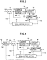
- Fig. 3 shows the first embodiment of the present invention.
- a transmission section (not shown) modulates, at a transmission modulation stage, the data of a reception baseband signal 100 input to an A/D converter 10 which is to be transmitted according to a modulation scheme such as BPSK, QPSK, FSK, or QAM.
- the modulated signal is converted into an RF signal and power-amplified to be radiated from an antenna.
- the radiated transmission signal is received by the reception antenna of a mobile unit or base station through a plurality of spatial transmission paths.
- the received signal is then converted into a reception baseband signal by a reception section through an RF amplification stage, band-pass filter, mixer, IF amplification stage, and the baseband demodulation stage of a detection means.
- this reception baseband signal 100 therefore, the transfer function becomes complicated through paths from the transmission modulation stage to the baseband demodulation stage according to the respective transmission systems.
- a mobile unit since its transfer function incessantly changes, the estimated transfer function of each symbol is obtained on the basis of pilot signals having a predetermined pattern and located on two sides of each of a plurality of symbols, and the optimal sampling timing is changed from b to c to b, as shown in Figs. 2A to 2C.
- the reception baseband signal 100 is converted into a digital baseband signal 110 by the A/D converter 10 under the above environment.
- the digital baseband signal 110 is then input to a transfer function interpolating section 20 and demodulating section 40.
- the transfer function interpolating section 20 uses the pilot portion contained in the input digital baseband signal 110 to estimate transfer functions up to the section 20 by interpolation processing, and outputs an estimated transfer function 120.
- the estimated transfer function 120 is further converted into a complex conjugate signal 150 by a conjugate section 30.
- the demodulating section 40 cancels the influence of the transmission path transfer function by using the digital baseband signal 110 and complex conjugate signal 150, and outputs a demodulation result 170.
- a timing control section 50 controls the operation of each component by outputting a sampling timing control signal 130, interpolation control signal 140, and demodulating section control signal 160. At this time, the timing control section 50 implements sampling point updating operation described with reference to Figs. 2A to 2C by using the interpolation control signal 140 and sampling timing control signal 130.
- interpolation synchronous detection is implemented by the transfer function interpolating section 20, conjugate section 30, and demodulating section 40, and an interpolation means indicates a transfer function interpolating section.
- a reception sampling point timing is updated by mainly updating the exclusive OR 103 supplied to the A/D converter 10 and also updating the interpolation control signal 140 and demodulating section control signal 160.
- the transfer function estimated by the transfer function interpolating section 20 is changed stepwise because it is difficult to continuously change the transfer function linearly in practice. This operation indicates that the transfer function is linearly changed from 0 dB to 20 dB, the base is then raised to linearly change the transfer function from 20 dB to 40 dB, and the transfer function is sequentially changed to 60 dB, 80 dB, and the like.
- changing the transfer functions of the transmission and reception circuits and transmitting and reception sections stepwise amounts to changing estimated transfer functions by changing the gain, phase, or the like of the reception RF amplifier having a through circuit stepwise by ON/OFF-operating the power supply within a transmission path system up to a reception baseband signal.
- the error probability is very low as compared with the prior art in which the estimated transfer function according to the sampling points b and c is updated at the start point of the pilot signal or the end point of the subsequent pilot signal as described with reference to Figs. 1A to 1C.
- Fig. 4 shows the arrangement of a reception section in a communication system according to the second embodiment of the present invention.
- a reception signal 190 received from an antenna is input to a radio section 70.
- a transmission section in a mobile unit or base station (not shown) modulates, at a transmission modulation stage, the data to be transmitted according to a modulation scheme such as BPSK, QPSK, FSK, or QAM.
- the modulated signal is converted into an RF signal, power-amplified, and radiated from the antenna.
- the radiated transmission signal is received by the reception antenna of a mobile unit or base station through a plurality of spatial transmission paths.
- the reception signal 190 is obtained.
- the radio section 70 includes an RF amplification stage, band-pass filter, local oscillator, frequency conversion mixer, IF amplification stage, and baseband demodulation stage as a detection means.
- the output from the baseband demodulation is the reception baseband signal.
- the transfer function becomes complicated through paths from the transmission modulation stage to the baseband demodulation stage according to the respective transmission systems.
- the estimated transfer function of each symbol is obtained on the receiving side having a predetermined pattern on the basis of pilot signals having a predetermined pattern and located on two sides of each of a plurality of symbols, and the optimal sampling timing is changed from b to c to b, as shown in Figs. 2A to 2C.
- the reception baseband signal 100 is converted into a digital baseband signal 110 by the A/D converter 10.
- the digital baseband signal 110 is then input to a transfer function interpolating section 20 and demodulating section 40.
- the transfer function interpolating section 20 uses the pilot portion contained in the input digital baseband signal 110 to estimate transfer functions up to the section 20, e.g., transfer functions Z1 and Z2 of equation (3) described above by interpolation processing, and outputs an estimated transfer function 120.
- the estimated transfer function 120 is further converted into a complex conjugate signal 150 by a conjugate section 30.
- the demodulating section 40 cancels the influence of the transmission path transfer function by using the digital baseband signal 110 and complex conjugate signal 150, and outputs a demodulation result 170 that coincides with the transmission data.
- the timing control section 60 controls the operation of each component by outputting a sampling timing control signal 130, interpolation control signal 140, and demodulating section control signal 160.
- the timing control section 60 also controls the radio section 70 by using a radio section control signal 180.
- the timing control section 60 implements the sampling point updating operation described with reference to Figs. 2A to 2C by using the interpolation control signal 140 for the transfer function interpolating section 20 and the sampling timing control signal 130 for the A/D converter 10.
- the timing control section 60 switches the variable gain range of a gain control section included in the radio section 70, as needed.
- the gain control section included in the radio section 70 includes a matching unit for impedance-matching with the antenna, a variable attenuator for adjusting the signal level, an RF amplification section capable of changing the gain, a variable band-pass filter capable of changing the reception band width, an IF amplification section capable of changing the gain, and the like.
- This gain control section can change the gain range and/or the phase characteristics by applying the radio section control signal 180 to any one of the above components.
Landscapes
- Engineering & Computer Science (AREA)
- Computer Networks & Wireless Communication (AREA)
- Signal Processing (AREA)
- Synchronisation In Digital Transmission Systems (AREA)
- Detection And Prevention Of Errors In Transmission (AREA)
- Cable Transmission Systems, Equalization Of Radio And Reduction Of Echo (AREA)
- Mobile Radio Communication Systems (AREA)
Applications Claiming Priority (2)
| Application Number | Priority Date | Filing Date | Title |
|---|---|---|---|
| JP24955998 | 1998-09-03 | ||
| JP24955998A JP3029031B2 (ja) | 1998-09-03 | 1998-09-03 | 内挿同期検波方法と無線通信システム |
Publications (3)
| Publication Number | Publication Date |
|---|---|
| EP0984562A2 true EP0984562A2 (fr) | 2000-03-08 |
| EP0984562A3 EP0984562A3 (fr) | 2003-05-28 |
| EP0984562B1 EP0984562B1 (fr) | 2005-11-23 |
Family
ID=17194807
Family Applications (1)
| Application Number | Title | Priority Date | Filing Date |
|---|---|---|---|
| EP99117375A Expired - Lifetime EP0984562B1 (fr) | 1998-09-03 | 1999-09-03 | Détection synchrone par interpolation de pilote dans un récepteur du type Rake |
Country Status (5)
| Country | Link |
|---|---|
| US (1) | US6912259B1 (fr) |
| EP (1) | EP0984562B1 (fr) |
| JP (1) | JP3029031B2 (fr) |
| KR (1) | KR100307004B1 (fr) |
| DE (1) | DE69928477T2 (fr) |
Cited By (4)
| Publication number | Priority date | Publication date | Assignee | Title |
|---|---|---|---|---|
| WO2000042713A1 (fr) * | 1999-01-11 | 2000-07-20 | Qualcomm Incorporated | Filtrage de signal en presence de discontinuites de phase dans un recepteur cdma |
| WO2002091608A1 (fr) * | 2001-05-10 | 2002-11-14 | Siemens Aktiengesellschaft | Procede d'estimation d'un canal de telephonie mobile, et appareil recepteur pour la telephonie mobile |
| WO2003065609A2 (fr) * | 2002-01-31 | 2003-08-07 | Qualcomm Incorporated | Interpolation de pilote pour un pilote commande par porte avec compensation pour des changements de phase induits |
| CN100454777C (zh) * | 2002-02-20 | 2009-01-21 | 三洋电机株式会社 | 无线装置、无线通信系统、空间通道控制方法 |
Families Citing this family (7)
| Publication number | Priority date | Publication date | Assignee | Title |
|---|---|---|---|---|
| JP3419726B2 (ja) | 2000-02-03 | 2003-06-23 | 松下電器産業株式会社 | メモリ回路および同期検波回路 |
| KR100685960B1 (ko) * | 2000-02-03 | 2007-02-23 | 엘지전자 주식회사 | 파일럿 패턴을 이용한 프레임 동기 확인 및 동기 실패검출 방법 |
| US20040077319A1 (en) * | 2000-09-04 | 2004-04-22 | Hirotaka Koike | Radio base system, sampling error reducing method, and sampling error reducing program |
| JP4448633B2 (ja) * | 2001-08-31 | 2010-04-14 | 富士通株式会社 | 移動体通信端末 |
| US7903772B2 (en) * | 2005-02-04 | 2011-03-08 | Broadcom Corporation | Digital demodulator with improved hardware and power efficiency |
| US9455822B2 (en) * | 2012-08-31 | 2016-09-27 | Mitsubishi Electric Corporation | Receiver, transmitter, and communication method |
| CN109905137B (zh) * | 2017-12-11 | 2020-11-24 | 博通集成电路(上海)股份有限公司 | 用于确定采样相位的接收机和确定采样相位的方法 |
Citations (5)
| Publication number | Priority date | Publication date | Assignee | Title |
|---|---|---|---|---|
| WO1991020142A1 (fr) * | 1990-06-12 | 1991-12-26 | Motorola, Inc. | Technique de combinaison en diversite a rapport maximum |
| EP0535403A1 (fr) * | 1991-10-01 | 1993-04-07 | Nec Corporation | Réception de signaux de données numérique TDMA avec compensation de dispertion de canal |
| US5537419A (en) * | 1991-06-27 | 1996-07-16 | Hughes Electronics | Receiver sample timing adjustment using channel impulse response |
| EP0802656A2 (fr) * | 1996-04-19 | 1997-10-22 | Wavecom | Signal numérique à blocs de référence multiples pour l'estimation de canal, procédés d'estimation de canal et récepteurs correspondants |
| US5692015A (en) * | 1994-06-22 | 1997-11-25 | Ntt Mobile Communications Network, Inc. | Coherent detector and a coherent detection method for a digital communication receiver |
Family Cites Families (9)
| Publication number | Priority date | Publication date | Assignee | Title |
|---|---|---|---|---|
| US5375146A (en) * | 1993-05-06 | 1994-12-20 | Comsat Corporation | Digital frequency conversion and tuning scheme for microwave radio receivers and transmitters |
| JP3153869B2 (ja) * | 1993-05-11 | 2001-04-09 | 株式会社日立国際電気 | フェージング歪補償方式及びその回路 |
| CN1059529C (zh) * | 1994-06-23 | 2000-12-13 | Ntt移动通信网株式会社 | 用于接收码分多址信号的方法和装置 |
| JP3243776B2 (ja) * | 1995-01-06 | 2002-01-07 | 株式会社エヌ・ティ・ティ・ドコモ | 周波数ホッピング伝送方法 |
| JP3310160B2 (ja) * | 1996-03-29 | 2002-07-29 | 松下電器産業株式会社 | スペクトラム拡散方式受信装置 |
| JP3103311B2 (ja) * | 1996-10-03 | 2000-10-30 | 国際電気株式会社 | Rake受信機 |
| JP3311609B2 (ja) * | 1996-10-18 | 2002-08-05 | 富士通株式会社 | 移動通信システム |
| JP3006679B2 (ja) * | 1997-01-16 | 2000-02-07 | 日本電気株式会社 | セルラー移動電話システム |
| US6351458B2 (en) * | 1997-09-22 | 2002-02-26 | Matsushita Electric Industrial Co., Ltd. | CDMA cellular wireless communication system |
-
1998
- 1998-09-03 JP JP24955998A patent/JP3029031B2/ja not_active Expired - Fee Related
-
1999
- 1999-09-02 US US09/389,289 patent/US6912259B1/en not_active Expired - Lifetime
- 1999-09-03 EP EP99117375A patent/EP0984562B1/fr not_active Expired - Lifetime
- 1999-09-03 DE DE1999628477 patent/DE69928477T2/de not_active Expired - Lifetime
- 1999-09-03 KR KR1019990037285A patent/KR100307004B1/ko not_active IP Right Cessation
Patent Citations (5)
| Publication number | Priority date | Publication date | Assignee | Title |
|---|---|---|---|---|
| WO1991020142A1 (fr) * | 1990-06-12 | 1991-12-26 | Motorola, Inc. | Technique de combinaison en diversite a rapport maximum |
| US5537419A (en) * | 1991-06-27 | 1996-07-16 | Hughes Electronics | Receiver sample timing adjustment using channel impulse response |
| EP0535403A1 (fr) * | 1991-10-01 | 1993-04-07 | Nec Corporation | Réception de signaux de données numérique TDMA avec compensation de dispertion de canal |
| US5692015A (en) * | 1994-06-22 | 1997-11-25 | Ntt Mobile Communications Network, Inc. | Coherent detector and a coherent detection method for a digital communication receiver |
| EP0802656A2 (fr) * | 1996-04-19 | 1997-10-22 | Wavecom | Signal numérique à blocs de référence multiples pour l'estimation de canal, procédés d'estimation de canal et récepteurs correspondants |
Cited By (7)
| Publication number | Priority date | Publication date | Assignee | Title |
|---|---|---|---|---|
| WO2000042713A1 (fr) * | 1999-01-11 | 2000-07-20 | Qualcomm Incorporated | Filtrage de signal en presence de discontinuites de phase dans un recepteur cdma |
| US6594303B1 (en) | 1999-01-11 | 2003-07-15 | Qualcomm Incorporated | Coherent demodulator for use in the presence of phase discontinuities |
| WO2002091608A1 (fr) * | 2001-05-10 | 2002-11-14 | Siemens Aktiengesellschaft | Procede d'estimation d'un canal de telephonie mobile, et appareil recepteur pour la telephonie mobile |
| WO2003065609A2 (fr) * | 2002-01-31 | 2003-08-07 | Qualcomm Incorporated | Interpolation de pilote pour un pilote commande par porte avec compensation pour des changements de phase induits |
| WO2003065609A3 (fr) * | 2002-01-31 | 2003-11-13 | Qualcomm Inc | Interpolation de pilote pour un pilote commande par porte avec compensation pour des changements de phase induits |
| US7133437B2 (en) | 2002-01-31 | 2006-11-07 | Qualcomm Incorporated | Pilot interpolation for a gated pilot with compensation for induced phase changes |
| CN100454777C (zh) * | 2002-02-20 | 2009-01-21 | 三洋电机株式会社 | 无线装置、无线通信系统、空间通道控制方法 |
Also Published As
| Publication number | Publication date |
|---|---|
| KR20000028638A (ko) | 2000-05-25 |
| EP0984562A3 (fr) | 2003-05-28 |
| EP0984562B1 (fr) | 2005-11-23 |
| DE69928477T2 (de) | 2006-08-17 |
| KR100307004B1 (ko) | 2001-11-05 |
| DE69928477D1 (de) | 2005-12-29 |
| JP3029031B2 (ja) | 2000-04-04 |
| JP2000078107A (ja) | 2000-03-14 |
| US6912259B1 (en) | 2005-06-28 |
Similar Documents
| Publication | Publication Date | Title |
|---|---|---|
| EP0715440B1 (fr) | Detecteur synchrone et procede de synchronisation pour un recepteur numerique de telecommunications | |
| US6243412B1 (en) | Adaptive array transmitter receiver | |
| US5694388A (en) | CDMA demodulator and demodulation method | |
| KR960013962B1 (ko) | 두개 이상의 안테나를 갖는 비터비 수신기의 페이딩의 영향을 감소시키는 방법 | |
| JP2734953B2 (ja) | Cdma受信装置 | |
| EP1096698B1 (fr) | Appareil de réception et procédé de traitement de réception | |
| US6625202B1 (en) | Mobile station for spread spectrum communication | |
| KR20040061006A (ko) | 송신 채널간의 이득 오프셋을 결정하는 방법 | |
| US6836507B1 (en) | Symbol synchronizer for software defined communications system signal combiner | |
| US6047023A (en) | Swept frequency modulation and demodulation technique | |
| US5442661A (en) | Path gain estimation in a receiver | |
| JPH06169273A (ja) | ダイバーシチを行なう無線受信機、送信機、および中継器 | |
| US20010050950A1 (en) | Received path timing detecting circuit at DS-CDMA system | |
| EP0984562B1 (fr) | Détection synchrone par interpolation de pilote dans un récepteur du type Rake | |
| EP1615364A1 (fr) | Recepteur radio, appareil de station mobile, appareil de station de base, et procede de reception radio | |
| JP3029030B2 (ja) | パイロット信号を含む受信信号の復調方法およびその装置 | |
| KR20000076706A (ko) | 라그랑제 다항식 보간법을 이용한 채널 왜곡의 보상 방법및 시스템 | |
| EP1093186A1 (fr) | Radioemetteur et procede de reglage de la directivite d'emission | |
| US8036303B2 (en) | Transmitter apparatus | |
| US6690713B1 (en) | Tracking loop for a code division multiple access (CDMA) system | |
| US7209510B2 (en) | Channel estimation system for a wideband code division multiple access (WCDMA) communication system | |
| KR100557112B1 (ko) | 이동통신시스템의 수신단에서의 주파수 오차를 추정하여 결합하는 장치 | |
| JP3718403B2 (ja) | レイク受信機 | |
| JP4470798B2 (ja) | 無線通信装置及び方法 | |
| JP2000252960A (ja) | Rake受信装置 |
Legal Events
| Date | Code | Title | Description |
|---|---|---|---|
| PUAI | Public reference made under article 153(3) epc to a published international application that has entered the european phase |
Free format text: ORIGINAL CODE: 0009012 |
|
| AK | Designated contracting states |
Kind code of ref document: A2 Designated state(s): AT BE CH CY DE DK ES FI FR GB GR IE IT LI LU MC NL PT SE |
|
| AX | Request for extension of the european patent |
Free format text: AL;LT;LV;MK;RO;SI |
|
| RIC1 | Information provided on ipc code assigned before grant |
Free format text: 7H 04B 1/707 A, 7H 04L 25/02 B, 7H 04L 7/04 B |
|
| PUAL | Search report despatched |
Free format text: ORIGINAL CODE: 0009013 |
|
| RIC1 | Information provided on ipc code assigned before grant |
Ipc: 7H 04B 1/707 B Ipc: 7H 04L 7/04 B Ipc: 7H 04L 25/02 A |
|
| AK | Designated contracting states |
Designated state(s): AT BE CH CY DE DK ES FI FR GB GR IE IT LI LU MC NL PT SE |
|
| AX | Request for extension of the european patent |
Extension state: AL LT LV MK RO SI |
|
| 17P | Request for examination filed |
Effective date: 20030414 |
|
| AKX | Designation fees paid |
Designated state(s): DE GB |
|
| 17Q | First examination report despatched |
Effective date: 20041006 |
|
| GRAP | Despatch of communication of intention to grant a patent |
Free format text: ORIGINAL CODE: EPIDOSNIGR1 |
|
| GRAS | Grant fee paid |
Free format text: ORIGINAL CODE: EPIDOSNIGR3 |
|
| GRAA | (expected) grant |
Free format text: ORIGINAL CODE: 0009210 |
|
| AK | Designated contracting states |
Kind code of ref document: B1 Designated state(s): DE GB |
|
| REG | Reference to a national code |
Ref country code: GB Ref legal event code: FG4D |
|
| REF | Corresponds to: |
Ref document number: 69928477 Country of ref document: DE Date of ref document: 20051229 Kind code of ref document: P |
|
| PLBE | No opposition filed within time limit |
Free format text: ORIGINAL CODE: 0009261 |
|
| STAA | Information on the status of an ep patent application or granted ep patent |
Free format text: STATUS: NO OPPOSITION FILED WITHIN TIME LIMIT |
|
| 26N | No opposition filed |
Effective date: 20060824 |
|
| REG | Reference to a national code |
Ref country code: GB Ref legal event code: 732E Free format text: REGISTERED BETWEEN 20141023 AND 20141029 |
|
| PGFP | Annual fee paid to national office [announced via postgrant information from national office to epo] |
Ref country code: GB Payment date: 20160831 Year of fee payment: 18 Ref country code: DE Payment date: 20160831 Year of fee payment: 18 |
|
| REG | Reference to a national code |
Ref country code: DE Ref legal event code: R119 Ref document number: 69928477 Country of ref document: DE |
|
| GBPC | Gb: european patent ceased through non-payment of renewal fee |
Effective date: 20170903 |
|
| PG25 | Lapsed in a contracting state [announced via postgrant information from national office to epo] |
Ref country code: DE Free format text: LAPSE BECAUSE OF NON-PAYMENT OF DUE FEES Effective date: 20180404 Ref country code: GB Free format text: LAPSE BECAUSE OF NON-PAYMENT OF DUE FEES Effective date: 20170903 |