EP0982839A2 - Moteur synchrone linéaire - Google Patents
Moteur synchrone linéaire Download PDFInfo
- Publication number
- EP0982839A2 EP0982839A2 EP19990115782 EP99115782A EP0982839A2 EP 0982839 A2 EP0982839 A2 EP 0982839A2 EP 19990115782 EP19990115782 EP 19990115782 EP 99115782 A EP99115782 A EP 99115782A EP 0982839 A2 EP0982839 A2 EP 0982839A2
- Authority
- EP
- European Patent Office
- Prior art keywords
- permanent magnets
- carrier material
- linear motor
- magnetic
- synchronous linear
- Prior art date
- Legal status (The legal status is an assumption and is not a legal conclusion. Google has not performed a legal analysis and makes no representation as to the accuracy of the status listed.)
- Withdrawn
Links
Images
Classifications
-
- H—ELECTRICITY
- H02—GENERATION; CONVERSION OR DISTRIBUTION OF ELECTRIC POWER
- H02K—DYNAMO-ELECTRIC MACHINES
- H02K41/00—Propulsion systems in which a rigid body is moved along a path due to dynamo-electric interaction between the body and a magnetic field travelling along the path
- H02K41/02—Linear motors; Sectional motors
- H02K41/03—Synchronous motors; Motors moving step by step; Reluctance motors
- H02K41/031—Synchronous motors; Motors moving step by step; Reluctance motors of the permanent magnet type
Definitions
- the invention relates to a synchronous linear motor and its Manufacturing process.
- a linear motor is known from EP 0 784 371 A1 Permanent magnets are arranged on a yoke, the Permanent magnets in their position due to an amagnetic layer are fixed.
- the disadvantage here is that the production such a linear motor is cumbersome, as well Height of such a secondary part for certain applications is not suitable.
- a linear motor is also known from US Pat. No. 5,130,583. whose permanent magnet is arranged on a yoke, the is in turn on a fixed base plate. Another disadvantage is the increased volume and the Type of attachment of the permanent magnets on the base plate.
- the invention is therefore based on the object of a synchronous linear motor with little installation effort, comparatively to create low weight, which is a comparatively high positional precision of the permanent magnets to be attached to the secondary part having.
- a synchronous linear motor solved with: at least one primary part and at least a secondary part, which has a series of permanent magnets, the permanent magnets on a magnetically conductive Carrier material are attached to a magnetic conductive machine bed can be arranged.
- the permanent magnets, the carrier material and the non-magnetic cover form a closed arrangement which absorbs the forces introduced from the outside.
- the non-magnetic cover which, combined with the carrier material, increases the rigidity of this arrangement, can preferably also only be an assembly aid in order to achieve further weight savings for the synchronous linear motor.
- the magnetic inference is essentially no longer taken from a magnetically conductive plate located on the secondary part, but from the machine bed itself, so that considerable weight savings occur.
- the carrier material is magnetically saturated, so that the arrangement Carrier material, permanent magnets, non-magnetic cover "adheres to the machine bed.
- the arranged permanent magnets do not necessarily have to parallel gaps, preferably Column, have, or rather are arranged obliquely Permanent magnets with conical spaces possible i.a. in the end areas of the primary part of a synchronous linear motor to get a ripple compensation.
- the spaces are preferably covered with a liquid, hardened non-magnetic material. This occurs a further increase in the rigidity of the assembly.
- the gaps between permanent magnets and non-magnetic Cover can be filled with it.
- the non-magnetic cover When using the non-magnetic cover as an assembly aid, it is removed after the curing process.
- the subsequent magnetization of the permanent magnets remains the permanent magnets on their originally assigned Squares.
- the overall construction is much lighter than comparable ones synchronous linear motors known from the prior art.
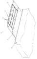
- This carrier material 3 is made of magnetic conductive material, e.g. Iron, and so thin that magnetic saturation occurs.
- the permanent magnets 2 are preferably with an adhesive 5 on this attached thin magnetically conductive carrier material 3.
- This carrier material 3 equipped with permanent magnets 2 has a thin non-magnetic cover 1, e.g. Stainless steel, on.
- This non-magnetic cover 1 is with the permanent magnets 2 and / or the carrier material 3 by adhesive 5 or other common connection types.
- the gaps 4 are preferably with liquid hardening filled in non-magnetic material.
- the non-magnetic cover 1 preferably remains for reasons of stability on the permanent magnet 2 provided carrier material 3. After hardening is a movement the permanent magnets 2 to each other and on the carrier material 3 no longer possible and the permanent magnets 2 can be magnetized.
- the carrier material 3 and the non-magnetic Cover 1 of the permanent magnets 2 form a closed Profile that represents the external forces absorbs and the penetration of moisture or dirt prevented.
- a soldered or welded connection the non-magnetic cover 1 with the carrier material 3 an extremely rigid arrangement is formed to accommodate existing tensile forces to record.
- the carrier material 3 is magnetically saturated, so that the overall arrangement Carrier material 3 with permanent magnets 2 and non-magnetic cover 1 "adheres to the machine bed 6. It is not absolutely necessary to fasten the overall arrangement to the machine bed 6, but it can be carried out using conventional means of form, friction or material engagement.
- the magnetic forces that try Lifting permanent magnets 2 off the machine bed 6 are in equilibrium with the magnetic forces that try to hold the permanent magnets 2 on the machine bed 6. Since the lifting magnetic forces are consistently smaller than the attractive magnetic forces due to the air gap of the synchronous linear motor which is always present, there are no fastenings between Machine bed 6 and the overall arrangement necessary.
- the overall arrangement shows a considerable weight reduction compared to conventional synchronous linear motors.
- This procedure can also be used for rotary motors, e.g. Synchronous motors.
Applications Claiming Priority (2)
| Application Number | Priority Date | Filing Date | Title |
|---|---|---|---|
| DE1998138132 DE19838132B4 (de) | 1998-08-21 | 1998-08-21 | Synchronlinearmotor |
| DE19838132 | 1998-08-21 |
Publications (1)
| Publication Number | Publication Date |
|---|---|
| EP0982839A2 true EP0982839A2 (fr) | 2000-03-01 |
Family
ID=7878360
Family Applications (1)
| Application Number | Title | Priority Date | Filing Date |
|---|---|---|---|
| EP19990115782 Withdrawn EP0982839A2 (fr) | 1998-08-21 | 1999-08-10 | Moteur synchrone linéaire |
Country Status (2)
| Country | Link |
|---|---|
| EP (1) | EP0982839A2 (fr) |
| DE (1) | DE19838132B4 (fr) |
Cited By (4)
| Publication number | Priority date | Publication date | Assignee | Title |
|---|---|---|---|---|
| EP1672772A2 (fr) * | 2004-12-15 | 2006-06-21 | Fanuc Ltd | Moteur linéaire |
| ITPD20110124A1 (it) * | 2011-04-15 | 2012-10-16 | Topp S P A A Socio Unico | Guida per attuatori lineari a magneti permanenti |
| EP3232550A1 (fr) * | 2016-04-12 | 2017-10-18 | Robert Bosch Gmbh | Partie secondaire d'un moteur linéaire |
| US10858192B2 (en) | 2017-04-21 | 2020-12-08 | Beckhoff Automation Gmbh | Conveying device and linear transport system |
Families Citing this family (2)
| Publication number | Priority date | Publication date | Assignee | Title |
|---|---|---|---|---|
| DE19936064B4 (de) * | 1999-07-30 | 2011-07-07 | Siemens AG, 80333 | Sekundärteil für einen Linearmotor und Linearmotor sowie Verfahren zur Herstellung eines Sekundärteils |
| DE10233900A1 (de) * | 2002-07-25 | 2004-02-19 | Vacuumschmelze Gmbh & Co. Kg | Permanentmagnetanordnung für ebene Linearantriebe |
Family Cites Families (4)
| Publication number | Priority date | Publication date | Assignee | Title |
|---|---|---|---|---|
| US5130583A (en) * | 1989-11-13 | 1992-07-14 | Ricoh Company, Ltd. | Linear motor |
| DE29520879U1 (de) * | 1995-02-03 | 1996-04-11 | Krauss Maffei Ag | Synchron-Linearmotor |
| EP0784371A4 (fr) * | 1995-07-03 | 2000-05-10 | Fanuc Ltd | Piece polaire d'aimant permanent pour moteurs lineaires |
| DE19622262A1 (de) * | 1996-06-03 | 1997-12-04 | Blum Gmbh | Verfahren und Vorrichtung zum Aufbringen von Permanentmagnetelementen auf eine Unterlage |
-
1998
- 1998-08-21 DE DE1998138132 patent/DE19838132B4/de not_active Expired - Fee Related
-
1999
- 1999-08-10 EP EP19990115782 patent/EP0982839A2/fr not_active Withdrawn
Cited By (6)
| Publication number | Priority date | Publication date | Assignee | Title |
|---|---|---|---|---|
| EP1672772A2 (fr) * | 2004-12-15 | 2006-06-21 | Fanuc Ltd | Moteur linéaire |
| EP1672772A3 (fr) * | 2004-12-15 | 2008-03-05 | Fanuc Ltd | Moteur linéaire |
| ITPD20110124A1 (it) * | 2011-04-15 | 2012-10-16 | Topp S P A A Socio Unico | Guida per attuatori lineari a magneti permanenti |
| EP2512016A1 (fr) * | 2011-04-15 | 2012-10-17 | Topp S.p.A. A Socio Unico | Guide pour actionneurs linéaires à aimant permanent |
| EP3232550A1 (fr) * | 2016-04-12 | 2017-10-18 | Robert Bosch Gmbh | Partie secondaire d'un moteur linéaire |
| US10858192B2 (en) | 2017-04-21 | 2020-12-08 | Beckhoff Automation Gmbh | Conveying device and linear transport system |
Also Published As
| Publication number | Publication date |
|---|---|
| DE19838132A1 (de) | 2000-03-02 |
| DE19838132B4 (de) | 2008-04-10 |
Similar Documents
| Publication | Publication Date | Title |
|---|---|---|
| EP2332155B1 (fr) | Culasse d aimant, composant micromecanique et procede de fabrication pour une culasse d' aimant et un composant micromecanique | |
| EP1995847B1 (fr) | Moteur planaire | |
| CH655210A5 (de) | Gleichstromlinearmotor. | |
| WO2000030240A9 (fr) | Moteur lineaire et partie secondaire pour moteur lineaire | |
| EP1301981B1 (fr) | Element secondaire d'un moteur lineaire, son procede de production, moteur lineaire dote de cet element secondaire et utilisation de ce moteur lineaire | |
| EP3032724A1 (fr) | Élément accessoire doté d'un gabarit | |
| EP0982839A2 (fr) | Moteur synchrone linéaire | |
| EP0756436A1 (fr) | Système magnétique pour transducteurs électromagnétiques | |
| EP3261223A2 (fr) | Machine électrique et procédé de fabrication d'une machine électrique | |
| DE102005020504A1 (de) | Drelphasenlinearantrieb mit reduzierter Kraftwelligkeit | |
| DE19953650A1 (de) | Verfahren zur Herstellung und Magazinierung von Einzelmagnetbauteilen sowie deren Montage zur Herstellung von miniatursisierten Magnetsystemen und solche Magnetsysteme | |
| EP3487049A1 (fr) | Moteur linéaire á flux transversal | |
| DE2707252A1 (de) | Einphasenschrittmotor | |
| DE112018000642T5 (de) | Magnetkodierer und Verfahren zu dessen Herstellung | |
| WO2012136464A2 (fr) | Moteur électrique comportant des dents en appui | |
| DE10046903C2 (de) | Elektromagnetische Bremse für einen elektrischen Antrieb | |
| DE102019110951A1 (de) | Verfahren und Vorrichtung zur Montage und/oder Demontage eines Permanentmagnet-Motors | |
| DE3246064A1 (de) | Gleichstromlinearmotor | |
| WO1998018193A9 (fr) | Dispositif d'entrainement direct de conception modulaire et mode de fabrication d'un composant actif d'un tel dispositif | |
| DE3148300A1 (de) | Magnetkopf und verfahren zum herstellen eines magnetkopfes | |
| DE60009182T2 (de) | Drehkupplung für die magnetische Anordnung von zwei Bauteilen, einem Kraftbauteil und einem Arbeitsbauteil | |
| EP0135055A1 (fr) | Dispositif d'entraînement à fonctionnement pas à pas | |
| DE10318482B3 (de) | Vorrichtung zum Messen relativer Beschleunigungen | |
| DE2365030A1 (de) | Elektromagnetischer stereotonabnehmer | |
| DE2360845C3 (de) | Drehmagnetmeßwerk |
Legal Events
| Date | Code | Title | Description |
|---|---|---|---|
| PUAI | Public reference made under article 153(3) epc to a published international application that has entered the european phase |
Free format text: ORIGINAL CODE: 0009012 |
|
| AK | Designated contracting states |
Kind code of ref document: A2 Designated state(s): AT BE CH CY DE DK ES FI FR GB GR IE IT LI LU MC NL PT SE |
|
| AX | Request for extension of the european patent |
Free format text: AL;LT;LV;MK;RO;SI |
|
| STAA | Information on the status of an ep patent application or granted ep patent |
Free format text: STATUS: THE APPLICATION IS DEEMED TO BE WITHDRAWN |
|
| 18D | Application deemed to be withdrawn |
Effective date: 20020301 |