EP0982839A2 - Linear synchronous motor - Google Patents
Linear synchronous motor Download PDFInfo
- Publication number
- EP0982839A2 EP0982839A2 EP19990115782 EP99115782A EP0982839A2 EP 0982839 A2 EP0982839 A2 EP 0982839A2 EP 19990115782 EP19990115782 EP 19990115782 EP 99115782 A EP99115782 A EP 99115782A EP 0982839 A2 EP0982839 A2 EP 0982839A2
- Authority
- EP
- European Patent Office
- Prior art keywords
- permanent magnets
- carrier material
- linear motor
- magnetic
- synchronous linear
- Prior art date
- Legal status (The legal status is an assumption and is not a legal conclusion. Google has not performed a legal analysis and makes no representation as to the accuracy of the status listed.)
- Withdrawn
Links
Images
Classifications
-
- H—ELECTRICITY
- H02—GENERATION; CONVERSION OR DISTRIBUTION OF ELECTRIC POWER
- H02K—DYNAMO-ELECTRIC MACHINES
- H02K41/00—Propulsion systems in which a rigid body is moved along a path due to dynamo-electric interaction between the body and a magnetic field travelling along the path
- H02K41/02—Linear motors; Sectional motors
- H02K41/03—Synchronous motors; Motors moving step by step; Reluctance motors
- H02K41/031—Synchronous motors; Motors moving step by step; Reluctance motors of the permanent magnet type
Definitions
- the invention relates to a synchronous linear motor and its Manufacturing process.
- a linear motor is known from EP 0 784 371 A1 Permanent magnets are arranged on a yoke, the Permanent magnets in their position due to an amagnetic layer are fixed.
- the disadvantage here is that the production such a linear motor is cumbersome, as well Height of such a secondary part for certain applications is not suitable.
- a linear motor is also known from US Pat. No. 5,130,583. whose permanent magnet is arranged on a yoke, the is in turn on a fixed base plate. Another disadvantage is the increased volume and the Type of attachment of the permanent magnets on the base plate.
- the invention is therefore based on the object of a synchronous linear motor with little installation effort, comparatively to create low weight, which is a comparatively high positional precision of the permanent magnets to be attached to the secondary part having.
- a synchronous linear motor solved with: at least one primary part and at least a secondary part, which has a series of permanent magnets, the permanent magnets on a magnetically conductive Carrier material are attached to a magnetic conductive machine bed can be arranged.
- the permanent magnets, the carrier material and the non-magnetic cover form a closed arrangement which absorbs the forces introduced from the outside.
- the non-magnetic cover which, combined with the carrier material, increases the rigidity of this arrangement, can preferably also only be an assembly aid in order to achieve further weight savings for the synchronous linear motor.
- the magnetic inference is essentially no longer taken from a magnetically conductive plate located on the secondary part, but from the machine bed itself, so that considerable weight savings occur.
- the carrier material is magnetically saturated, so that the arrangement Carrier material, permanent magnets, non-magnetic cover "adheres to the machine bed.
- the arranged permanent magnets do not necessarily have to parallel gaps, preferably Column, have, or rather are arranged obliquely Permanent magnets with conical spaces possible i.a. in the end areas of the primary part of a synchronous linear motor to get a ripple compensation.
- the spaces are preferably covered with a liquid, hardened non-magnetic material. This occurs a further increase in the rigidity of the assembly.
- the gaps between permanent magnets and non-magnetic Cover can be filled with it.
- the non-magnetic cover When using the non-magnetic cover as an assembly aid, it is removed after the curing process.
- the subsequent magnetization of the permanent magnets remains the permanent magnets on their originally assigned Squares.
- the overall construction is much lighter than comparable ones synchronous linear motors known from the prior art.
- This carrier material 3 is made of magnetic conductive material, e.g. Iron, and so thin that magnetic saturation occurs.
- the permanent magnets 2 are preferably with an adhesive 5 on this attached thin magnetically conductive carrier material 3.
- This carrier material 3 equipped with permanent magnets 2 has a thin non-magnetic cover 1, e.g. Stainless steel, on.
- This non-magnetic cover 1 is with the permanent magnets 2 and / or the carrier material 3 by adhesive 5 or other common connection types.
- the gaps 4 are preferably with liquid hardening filled in non-magnetic material.
- the non-magnetic cover 1 preferably remains for reasons of stability on the permanent magnet 2 provided carrier material 3. After hardening is a movement the permanent magnets 2 to each other and on the carrier material 3 no longer possible and the permanent magnets 2 can be magnetized.
- the carrier material 3 and the non-magnetic Cover 1 of the permanent magnets 2 form a closed Profile that represents the external forces absorbs and the penetration of moisture or dirt prevented.
- a soldered or welded connection the non-magnetic cover 1 with the carrier material 3 an extremely rigid arrangement is formed to accommodate existing tensile forces to record.
- the carrier material 3 is magnetically saturated, so that the overall arrangement Carrier material 3 with permanent magnets 2 and non-magnetic cover 1 "adheres to the machine bed 6. It is not absolutely necessary to fasten the overall arrangement to the machine bed 6, but it can be carried out using conventional means of form, friction or material engagement.
- the magnetic forces that try Lifting permanent magnets 2 off the machine bed 6 are in equilibrium with the magnetic forces that try to hold the permanent magnets 2 on the machine bed 6. Since the lifting magnetic forces are consistently smaller than the attractive magnetic forces due to the air gap of the synchronous linear motor which is always present, there are no fastenings between Machine bed 6 and the overall arrangement necessary.
- the overall arrangement shows a considerable weight reduction compared to conventional synchronous linear motors.
- This procedure can also be used for rotary motors, e.g. Synchronous motors.
Landscapes
- Engineering & Computer Science (AREA)
- Physics & Mathematics (AREA)
- Chemical & Material Sciences (AREA)
- Combustion & Propulsion (AREA)
- Electromagnetism (AREA)
- Power Engineering (AREA)
- Linear Motors (AREA)
Abstract
Description
Die Erfindung betrifft einen Synchronlinearmotor und dessen Herstellverfahren.The invention relates to a synchronous linear motor and its Manufacturing process.
Bei Synchronlinearmotoren, die einen Sekundärteil aufweisen, der aus einer langgestreckten amagnetischen Trägerplatte besteht, auf der jeweils zueinander angeordnete Permanentmagnete festgeklebt sind, besteht das Problem, daß sich die in amagnetischer Umgebung anzuordnenden Permanentmagnete während des Klebevorgangs infolge der Einrückung der gegenseitigen magnetischen Kräfte fortbewegen und sich nicht auf den vorgesehenen Positionen fixieren lassen.With synchronous linear motors that have a secondary part, which consists of an elongated non-magnetic carrier plate, on each other arranged permanent magnets are stuck, the problem is that the in permanent magnets to be arranged during the non-magnetic environment the gluing process due to the indentation of the mutual magnetic forces move and not on the intended Have positions fixed.
Zur Vermeidung dieser Nachteile werden gemäß der DE 195 03 511 A1 die Permanentmagnete eines dort beschriebenen Synchronlinearmotors in einem Raster von Distanzelementen angeordnet, so daß eine Beeinflussung während der Montage auszuschließen ist.To avoid these disadvantages, according to DE 195 03 511 A1 the permanent magnets of one described there Synchronous linear motor arranged in a grid of spacer elements, so that there is no interference during assembly is.
Aus der EP 0 784 371 A1 ist ein Linearmotor bekannt, dessen Permanentmagnete auf einen Joch angeordnet sind, wobei die Permanentmagnete durch eine amagnetische Schicht in ihrer Lage fixiert sind. Nachteilig dabei ist, daß die Herstellung eines derartigen Linearmotors umständlich ist, als auch die Höhe eines derartigen Sekundärteils für gewisse Anwendungen nicht geeignet ist.A linear motor is known from EP 0 784 371 A1 Permanent magnets are arranged on a yoke, the Permanent magnets in their position due to an amagnetic layer are fixed. The disadvantage here is that the production such a linear motor is cumbersome, as well Height of such a secondary part for certain applications is not suitable.
Aus der US 5 130 583 ist ebenfalls ein Linearmotor bekannt, dessen Permanentmagnete auf einem Joch angeordnet wird, das sich wiederum auf einer ortsfesten Grundplatte befindet. Nachteilig dabei ist ebenfalls das erhöhte Bauvolumen und die Art der Befestigung der Permanentmagnete auf der Grundplatte. A linear motor is also known from US Pat. No. 5,130,583. whose permanent magnet is arranged on a yoke, the is in turn on a fixed base plate. Another disadvantage is the increased volume and the Type of attachment of the permanent magnets on the base plate.
Nachteilig bei diesen Distanzelementen ist der zusätzliche Materialaufwand, und die zusätzliche Befestigung dieser Distanzelemente in oder an der Trägerplatte.The disadvantage of these spacer elements is the additional one Material costs, and the additional attachment of these spacers in or on the carrier plate.
Der Erfindung liegt daher die Aufgabe zugrunde, einen Synchronlinearmotor mit geringem Montageaufwand, vergleichsweise geringem Eigengewicht zu schaffen, der eine vergleichsweise hohe Lagepräzision der am Sekundärteil zu befestigenden Permanentmagnete aufweist.The invention is therefore based on the object of a synchronous linear motor with little installation effort, comparatively to create low weight, which is a comparatively high positional precision of the permanent magnets to be attached to the secondary part having.
Diese Aufgabe wird erfindungsgemäß durch ein Synchronlinearmotor gelöst mit: mindestens einem Primärteil und mindestens einem Sekundärteil, der eine Folge von Permanentmagneten aufweist, wobei die Permanentmagnete auf einem magnetisch leitenden Trägermaterial angebracht sind, das auf einem magnetisch leitenden Maschinenbett anordenbar ist.This object is achieved by a synchronous linear motor solved with: at least one primary part and at least a secondary part, which has a series of permanent magnets, the permanent magnets on a magnetically conductive Carrier material are attached to a magnetic conductive machine bed can be arranged.
Ein derartiger Synchronlinearmotor wird durch ein Verfahren hergestellt, das folgende Schritte beinhaltet:
- nicht aufmagnetisierte Permanentmagnete werden auf einem vergleichsweise dünnen magnetisch leitenden Trägermaterial angebracht,
- diese Anordnung wird mit einer amagnetischen Abdeckung versehen,
- anschließend werden die Magnete aufmagnetisiert und als Gesamtgebilde auf einem magnetisch leitenden, den magnetischen Rückschluß bildenden Maschinenbett angebracht.
- permanent magnets that are not magnetized are attached to a comparatively thin magnetically conductive carrier material,
- this arrangement is provided with an amagnetic cover,
- the magnets are then magnetized and attached as a whole to a magnetically conductive machine bed which forms the magnetic yoke.
Die Permanentmagnete, das Trägermaterial und die amagnetische
Abdeckung bilden eine geschlossene Anordnung, die die von außen
eingeleiteten kräfte aufnimmt. Die amagnetische Abdeckung,
die verbunden mit dem Trägermaterial zur Erhöhung der
Steifigkeit dieser Anordnung führt, kann vorzugsweise auch
nur eine Montagehilfe darstellen, um so eine weitere Gewichtsersparnis
des Synchronlinearmotors zu erreichen. Der
magnetische Rückschluß wird im wesentlichen nicht mehr von
einer am Sekundärteil befindlichen magnetisch leitenden Platte,
sondern vom Maschinenbett selbst übernommen, sodaß eine
erhebliche Gewichtsersparnis eintritt. Das Trägermaterial ist
magnetisch gesättigt, so daß die Anordnung ![]()
![]()
Eine Befestigung der Anordnung ist dabei nicht unbedingt notwendig; die Magnetkräfte, die versuchen die Permanentmagnete vom Maschinenbett abzuheben, stehen im Kräftegleichgewicht zu den Magnetkräften, die versuchen die Permanentmagnete auf dem Maschinenbett festzuhalten. Da die abhebenden Magnetkräfte aufgrund des Luftspaltes des Synchronlinearmotors immer kleiner sind, als die anziehenden Magnetkräfte, sind keine Befestigungen in dieser Richtung notwendig.Fastening the arrangement is not absolutely necessary; the magnetic forces that the permanent magnets try Lifting off the machine bed is due to the balance of forces the magnetic forces that try the permanent magnets on the To hold the machine bed. Because the lifting magnetic forces due to the air gap of the synchronous linear motor always smaller than the attractive magnetic forces, are not attachments necessary in this direction.
Abhängig von der Größe der Anordnung stehen unterschiedliche Möglichkeiten zur Verfügung, die Längskräfte, vorzugsweise durch Reibkräfte in das Maschinenbett zu übertragen. Zusätzlich sind sämtliche form- und kraftschlüssigen Verbindungsarten zwischen der Anordnung und dem Maschinenbett einsetzbar.There are different ones depending on the size of the arrangement Possibilities available, the longitudinal forces, preferably transmitted into the machine bed by frictional forces. In addition are all positive and non-positive connection types can be used between the arrangement and the machine bed.
Die angeordneten Permanentmagnete müssen nicht notwendigerweise parallel ausgerichtete Zwischenräume, vorzugsweise Spalte, aufweisen, vielmehr sind auch schräg angeordnete oder Permanentmagnete mit konischen Zwishenräumen möglich um so u.a. in den Endbereichen des Primärteils eines Synchronlinearmotors einen Kraftwelligkeitsausgleich zu erhalten.The arranged permanent magnets do not necessarily have to parallel gaps, preferably Column, have, or rather are arranged obliquely Permanent magnets with conical spaces possible i.a. in the end areas of the primary part of a synchronous linear motor to get a ripple compensation.
Ebenso sind verschieden geometrisch gestaltete Permanentmagnete einsetzbar.There are also different geometrically designed permanent magnets applicable.
Durch nicht aufmagnetisierte Permanentmagnete läßt sich die Herstellung eines Synchronlinearmotors wesentlich vereinfachen, da sich die Permanentmagnete gegenseitig nicht an- beziehungsweise abstoßen und so die Montage durch zusätzliche Arbeitsgänge und Teile erschwert wird. This can be achieved by permanent magnets that are not magnetized Simplify the manufacture of a synchronous linear motor, since the permanent magnets do not turn on or on each other repel and so the assembly by additional Operations and parts is difficult.
Vorzugsweise werden die Zwischenräume mit einem flüssigen, aushärtenden amagnetischen Material ausgefüllt. Dadurch tritt eine weitere Erhöhung der Steifigkeit der Anordnung ein. Dabei sind in einer weiteren vorzugsweisen Ausgestaltung auch die Zwischenräume zwischen Permanentmagneten und amagnetischer Abdeckung damit ausfüllbar.The spaces are preferably covered with a liquid, hardened non-magnetic material. This occurs a further increase in the rigidity of the assembly. Here are also in a further preferred embodiment the gaps between permanent magnets and non-magnetic Cover can be filled with it.
Bei einer Verwendung der amagnetischen Abdeckung als Montagehilfe, wird diese nach dem Aushärtungsprozess entfernt.When using the non-magnetic cover as an assembly aid, it is removed after the curing process.
Die anschließende Aufmagnetisierung der Permanentmagnete belaßt die Permanentmagnete an ihren ursprünglich zugewiesenen Plätzen.The subsequent magnetization of the permanent magnets remains the permanent magnets on their originally assigned Squares.
Die Gesamtkonstruktion ist wesentlich leichter als vergleichbare aus dem Stand der Technik bekannte Synchronlinearmotoren.The overall construction is much lighter than comparable ones synchronous linear motors known from the prior art.
Die Erfindung sowie weitere vorteilhafte Ausgestaltungen der Erfindung gemäß Merkmalen der Unteransprüche werden im folgenden anhand eines schematisch dargestellten Ausführungsbeispiels in der Zeichnung näher erläutert. Dabei zeigen:
- FIG 1
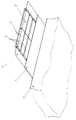
- den prinzipiellen Aufbau eines Sekundärteils eines Synchronlinearmotors.
- FIG. 1
- the basic structure of a secondary part of a synchronous linear motor.
FIG 1 zeigt einen Sekundärteil eines Synchronlinearmotors mit
vorzugsweise quaderförmigen Permanentmagneten 2, die in Zweierreihen
mit identischen Zwischenräumen 4 auf einem Trägermaterial
3 angeordnet sind. Dieses Trägermaterial 3 ist aus magnetisch
leitendem Material, z.B. Eisen, und so dünn, daß
sich eine magnetische Sättigung einstellt. Die Permanentmagnete
2 werden vorzugsweise mit einem Kleber 5 auf diesem
dünnen magnetisch leitendenden Trägermaterial 3 befestigt.
Dieses mit Permanentmagneten 2 bestückte Trägermaterial 3
weist eine dünne amagnetische Abdeckung 1, z.B. Edelstahl,
auf. Diese amagnetische Abdeckung 1 ist mit den Permanentmagenten
2 und/oder dem Trägermaterial 3 durch Kleber 5 oder
anderen allgemein üblichen Verbindungsarten verbunden.1 shows a secondary part of a synchronous linear motor
preferably cuboid
Die Zwischenräume 4 sind vorzugsweise mit flüssigem aushärtenden
amagnetischen Material ausgefüllt. Nach dem Aushärtungsprozess
verbleibt die amagnetische Abdeckung 1 vorzugsweise
aus Stabilitätsgründen auf dem mit Permanentmagneten 2
versehenen Trägermaterial 3. Nach der Aushärtung ist eine Bewegung
der Permanentmagnete 2 zueinander und auf dem Trägermaterial
3 nicht mehr möglich und die Permanentmagnete 2 können
aufmagnetisiert werden.The gaps 4 are preferably with liquid hardening
filled in non-magnetic material. After the curing process
the non-magnetic cover 1 preferably remains
for reasons of stability on the
Diese Anordnung wird anschließend auf das magnetisch leitende
Maschinenbett 6 gebracht. Das Trägermaterial 3 und die amagnetische
Abdeckung 1 der Permanentmagnete 2 bilden ein geschlossenes
Profil, das die von außen eingeleiteten Kräfte
aufnimmt und das Eindringen von Feuchtigkeit oder Schmutz
verhindert. Außerdem wird durch eine Löt- oder Schweißverbindung
der amagnetischen Abdeckung 1 mit dem Trägermaterial 3
eine äußerst steife Anordnung gebildet, um vorhandene Zugkräfte
aufzunehmen.This arrangement is then applied to the magnetically conductive
Das Trägermaterial 3 ist magnetisch gesättigt, so daß die Gesamtanordnung
Die Gesamtanordnung weist eine erhebliche Gewichtsreduktion gegenüber herkömmlichen Synchronllinearmotoren auf.The overall arrangement shows a considerable weight reduction compared to conventional synchronous linear motors.
Dieses Verfahren kann grundsätzlich auch für rotatorische Motoren, z.B. Synchronmotoren, eingesetzt werden.This procedure can also be used for rotary motors, e.g. Synchronous motors.
Claims (7)
Applications Claiming Priority (2)
| Application Number | Priority Date | Filing Date | Title |
|---|---|---|---|
| DE1998138132 DE19838132B4 (en) | 1998-08-21 | 1998-08-21 | Synchronous linear motor |
| DE19838132 | 1998-08-21 |
Publications (1)
| Publication Number | Publication Date |
|---|---|
| EP0982839A2 true EP0982839A2 (en) | 2000-03-01 |
Family
ID=7878360
Family Applications (1)
| Application Number | Title | Priority Date | Filing Date |
|---|---|---|---|
| EP19990115782 Withdrawn EP0982839A2 (en) | 1998-08-21 | 1999-08-10 | Linear synchronous motor |
Country Status (2)
| Country | Link |
|---|---|
| EP (1) | EP0982839A2 (en) |
| DE (1) | DE19838132B4 (en) |
Cited By (4)
| Publication number | Priority date | Publication date | Assignee | Title |
|---|---|---|---|---|
| EP1672772A2 (en) * | 2004-12-15 | 2006-06-21 | Fanuc Ltd | Linear motor |
| ITPD20110124A1 (en) * | 2011-04-15 | 2012-10-16 | Topp S P A A Socio Unico | GUIDE FOR PERMANENT MAGNETIC LINEAR ACTUATORS |
| EP3232550A1 (en) * | 2016-04-12 | 2017-10-18 | Robert Bosch Gmbh | Secondary part of a linear motor |
| US10858192B2 (en) | 2017-04-21 | 2020-12-08 | Beckhoff Automation Gmbh | Conveying device and linear transport system |
Families Citing this family (2)
| Publication number | Priority date | Publication date | Assignee | Title |
|---|---|---|---|---|
| DE19936064B4 (en) * | 1999-07-30 | 2011-07-07 | Siemens AG, 80333 | Secondary part for a linear motor and linear motor and method for producing a secondary part |
| DE10233900A1 (en) * | 2002-07-25 | 2004-02-19 | Vacuumschmelze Gmbh & Co. Kg | Permanent magnet structure for flat linear drive mechanisms has two or more permanent magnets of equal dimensions set out in a parallelogram and moving along a slanting edge to form a pole |
Family Cites Families (4)
| Publication number | Priority date | Publication date | Assignee | Title |
|---|---|---|---|---|
| US5130583A (en) * | 1989-11-13 | 1992-07-14 | Ricoh Company, Ltd. | Linear motor |
| DE19503511C5 (en) * | 1995-02-03 | 2010-11-04 | Siemens Ag | Synchronous linear motor |
| US5757091A (en) * | 1995-07-03 | 1998-05-26 | Fanuc Ltd. | Permanent magnet field pole for linear motor |
| DE19622262A1 (en) * | 1996-06-03 | 1997-12-04 | Blum Gmbh | Permanent magnet element fixing method e.g. for synchronous electrical machine parts secondary manufacture |
-
1998
- 1998-08-21 DE DE1998138132 patent/DE19838132B4/en not_active Expired - Fee Related
-
1999
- 1999-08-10 EP EP19990115782 patent/EP0982839A2/en not_active Withdrawn
Cited By (6)
| Publication number | Priority date | Publication date | Assignee | Title |
|---|---|---|---|---|
| EP1672772A2 (en) * | 2004-12-15 | 2006-06-21 | Fanuc Ltd | Linear motor |
| EP1672772A3 (en) * | 2004-12-15 | 2008-03-05 | Fanuc Ltd | Linear motor |
| ITPD20110124A1 (en) * | 2011-04-15 | 2012-10-16 | Topp S P A A Socio Unico | GUIDE FOR PERMANENT MAGNETIC LINEAR ACTUATORS |
| EP2512016A1 (en) * | 2011-04-15 | 2012-10-17 | Topp S.p.A. A Socio Unico | Guide for permanent-magnet linear actuators |
| EP3232550A1 (en) * | 2016-04-12 | 2017-10-18 | Robert Bosch Gmbh | Secondary part of a linear motor |
| US10858192B2 (en) | 2017-04-21 | 2020-12-08 | Beckhoff Automation Gmbh | Conveying device and linear transport system |
Also Published As
| Publication number | Publication date |
|---|---|
| DE19838132B4 (en) | 2008-04-10 |
| DE19838132A1 (en) | 2000-03-02 |
Similar Documents
| Publication | Publication Date | Title |
|---|---|---|
| EP2332155B1 (en) | Magnetic yoke, micromechanical component, and method for producing a magnetic yoke and a micromechanical component | |
| DE2162039C3 (en) | Positioning device | |
| DE19610754C1 (en) | Rotor for electrical machine, in particular transverse flux machine | |
| EP1995847B1 (en) | Planar motor | |
| CH655210A5 (en) | DC CURRENT ARM MOTOR. | |
| DE102004017507A1 (en) | Rotor arrangement for an electric machine | |
| WO2000030240A9 (en) | Linear motor and secondary part for said linear motor | |
| EP1301981B1 (en) | Secondary part of a linear motor and method for producing the same | |
| EP3032724A1 (en) | Secondary part with template | |
| EP0982839A2 (en) | Linear synchronous motor | |
| EP3261223A2 (en) | Electrical machine and method for manufacturing an electrical machine | |
| DE102005020504A1 (en) | Drelphasenlinearantrieb with reduced power ripple | |
| EP3487049A1 (en) | Linear motor comprising a transversal flux | |
| DE2707252A1 (en) | SINGLE PHASE MOTOR | |
| DE112018000642T5 (en) | Magnetic encoder and method for its production | |
| WO2012136464A2 (en) | Electric machine having supported teeth | |
| DE102019110951A1 (en) | Method and device for assembling and / or disassembling a permanent magnet motor | |
| WO1998018193A9 (en) | Modular direct driving device and method for manufacturing an active component of same | |
| DE3148300A1 (en) | MAGNETIC HEAD AND METHOD FOR PRODUCING A MAGNETIC HEAD | |
| DE60009182T2 (en) | Rotary coupling for the magnetic arrangement of two components, a power component and a work component | |
| AT337303B (en) | STATOR FOR ELECTRIC MACHINERY | |
| DE10318482B3 (en) | Acceleration measurement device, e.g. for machine tool use, comprises an eddy current generating assembly with planar sensor coils positioned so that their middle axis are coaxial with the center of secondary magnetic fields | |
| DE2241637A1 (en) | DISPLAY DEVICE WITH ROTATING RINGS | |
| DE2365030A1 (en) | Moving coil stereo pickup - is for scanning groove recordings modulated in two directions at 90 deg. to each other | |
| EP3993241A1 (en) | Secondary part for a linear motor, linear motor and construction kit for a linear motor with magnetic bodies and replacement bodies |
Legal Events
| Date | Code | Title | Description |
|---|---|---|---|
| PUAI | Public reference made under article 153(3) epc to a published international application that has entered the european phase |
Free format text: ORIGINAL CODE: 0009012 |
|
| AK | Designated contracting states |
Kind code of ref document: A2 Designated state(s): AT BE CH CY DE DK ES FI FR GB GR IE IT LI LU MC NL PT SE |
|
| AX | Request for extension of the european patent |
Free format text: AL;LT;LV;MK;RO;SI |
|
| STAA | Information on the status of an ep patent application or granted ep patent |
Free format text: STATUS: THE APPLICATION IS DEEMED TO BE WITHDRAWN |
|
| 18D | Application deemed to be withdrawn |
Effective date: 20020301 |