EP0982199A1 - Bestätigungsvorrichtung für einen luftsack - Google Patents
Bestätigungsvorrichtung für einen luftsack Download PDFInfo
- Publication number
- EP0982199A1 EP0982199A1 EP98911107A EP98911107A EP0982199A1 EP 0982199 A1 EP0982199 A1 EP 0982199A1 EP 98911107 A EP98911107 A EP 98911107A EP 98911107 A EP98911107 A EP 98911107A EP 0982199 A1 EP0982199 A1 EP 0982199A1
- Authority
- EP
- European Patent Office
- Prior art keywords
- time
- value
- inflator
- activation
- air bag
- Prior art date
- Legal status (The legal status is an assumption and is not a legal conclusion. Google has not performed a legal analysis and makes no representation as to the accuracy of the status listed.)
- Withdrawn
Links
Images


Classifications
-
- B—PERFORMING OPERATIONS; TRANSPORTING
- B60—VEHICLES IN GENERAL
- B60R—VEHICLES, VEHICLE FITTINGS, OR VEHICLE PARTS, NOT OTHERWISE PROVIDED FOR
- B60R21/00—Arrangements or fittings on vehicles for protecting or preventing injuries to occupants or pedestrians in case of accidents or other traffic risks
- B60R21/01—Electrical circuits for triggering passive safety arrangements, e.g. airbags, safety belt tighteners, in case of vehicle accidents or impending vehicle accidents
- B60R21/013—Electrical circuits for triggering passive safety arrangements, e.g. airbags, safety belt tighteners, in case of vehicle accidents or impending vehicle accidents including means for detecting collisions, impending collisions or roll-over
- B60R21/0132—Electrical circuits for triggering passive safety arrangements, e.g. airbags, safety belt tighteners, in case of vehicle accidents or impending vehicle accidents including means for detecting collisions, impending collisions or roll-over responsive to vehicle motion parameters, e.g. to vehicle longitudinal or transversal deceleration or speed value
- B60R21/0133—Electrical circuits for triggering passive safety arrangements, e.g. airbags, safety belt tighteners, in case of vehicle accidents or impending vehicle accidents including means for detecting collisions, impending collisions or roll-over responsive to vehicle motion parameters, e.g. to vehicle longitudinal or transversal deceleration or speed value by integrating the amplitude of the input signal
-
- B—PERFORMING OPERATIONS; TRANSPORTING
- B60—VEHICLES IN GENERAL
- B60R—VEHICLES, VEHICLE FITTINGS, OR VEHICLE PARTS, NOT OTHERWISE PROVIDED FOR
- B60R21/00—Arrangements or fittings on vehicles for protecting or preventing injuries to occupants or pedestrians in case of accidents or other traffic risks
- B60R21/01—Electrical circuits for triggering passive safety arrangements, e.g. airbags, safety belt tighteners, in case of vehicle accidents or impending vehicle accidents
- B60R21/013—Electrical circuits for triggering passive safety arrangements, e.g. airbags, safety belt tighteners, in case of vehicle accidents or impending vehicle accidents including means for detecting collisions, impending collisions or roll-over
-
- B—PERFORMING OPERATIONS; TRANSPORTING
- B60—VEHICLES IN GENERAL
- B60R—VEHICLES, VEHICLE FITTINGS, OR VEHICLE PARTS, NOT OTHERWISE PROVIDED FOR
- B60R21/00—Arrangements or fittings on vehicles for protecting or preventing injuries to occupants or pedestrians in case of accidents or other traffic risks
- B60R21/01—Electrical circuits for triggering passive safety arrangements, e.g. airbags, safety belt tighteners, in case of vehicle accidents or impending vehicle accidents
- B60R21/015—Electrical circuits for triggering passive safety arrangements, e.g. airbags, safety belt tighteners, in case of vehicle accidents or impending vehicle accidents including means for detecting the presence or position of passengers, passenger seats or child seats, and the related safety parameters therefor, e.g. speed or timing of airbag inflation in relation to occupant position or seat belt use
- B60R21/01558—Electrical circuits for triggering passive safety arrangements, e.g. airbags, safety belt tighteners, in case of vehicle accidents or impending vehicle accidents including means for detecting the presence or position of passengers, passenger seats or child seats, and the related safety parameters therefor, e.g. speed or timing of airbag inflation in relation to occupant position or seat belt use monitoring crash strength
-
- B—PERFORMING OPERATIONS; TRANSPORTING
- B60—VEHICLES IN GENERAL
- B60R—VEHICLES, VEHICLE FITTINGS, OR VEHICLE PARTS, NOT OTHERWISE PROVIDED FOR
- B60R21/00—Arrangements or fittings on vehicles for protecting or preventing injuries to occupants or pedestrians in case of accidents or other traffic risks
- B60R21/01—Electrical circuits for triggering passive safety arrangements, e.g. airbags, safety belt tighteners, in case of vehicle accidents or impending vehicle accidents
- B60R2021/01006—Mounting of electrical components in vehicles
Definitions
- the present invention relates to an activation control apparatus for an air bag system for activating the air bag system by detecting a vehicle collision, and more particularly, in an air bag system of the type that inflates one air bag using a plurality of inflators, the invention relates to a novel air bag inflation control apparatus that can make a proper determination of inflator activation mode and a correct decision to activate or not activate the inflators according to the severity of a collision.
- Air bag systems generally used in the past are of the type that inflates one air bag using a single inflator.
- the change of acceleration of a vehicle is constantly monitored using an acceleration sensor mounted in a passenger compartment, and the resulting acceleration signal is processed by performing appropriate mathematical operations such as first integration or second integration; then, the result is compared with a predetermined threshold value and, if it exceeds the threshold value, an activation signal is issued to an inflator ignition circuit to activate the inflator and thus inflate the air bag.
- the air bag Since this type of air bag system is designed, based on safety standards, to produce maximum performance in a frontal collision at 50 km/h, the air bag is inflated with designated characteristics if only the threshold value is exceeded, regardless of the severity of the collision or the position or posture of the vehicle occupant. Therefore, in a low-speed or medium-speed collision, the air bag is inflated with a inflating energy excessive for occupant protection, giving rise to the possibility that, if the occupant is seated close to the air bag, or in the case of a small sized occupant, the occupant may be injured by the inflation of the air bag.
- the acceleration sensor used to determine whether to activate or not activate the inflator there are two types according to the sensor mounting position: one is the integral type in which the sensor is assembled into the air bag module and mounted in the steering wheel, and the other is the separate type in which the sensor is on the driver's seat side in the passenger compartment.
- the acceleration sensor detects the impact of the collision transmitted through the steering shaft
- the acceleration sensor in the case of the separate type, is mounted on a bracket attached to the vehicle body and detects the impact of the collision transmitted to the inside of the passenger compartment through the vehicle body; in either case, the decision whether to inflate or not inflate the air bag is made based on the change of acceleration detected by the acceleration sensor mounted within the passenger compartment that has a structure of high rigidity and is less subjected to deformation in the event of a collision.
- Some vehicle types in which impacts at the front of the vehicle are difficult to transmit to the inside of the passenger compartment employ a system that uses an electronic acceleration sensor mounted inside the passenger compartment in combination with a mechanical sensor mounted in a crush zone, such as an engine compartment, in the forward part of the vehicle, but since the mechanical sensor, because of its characteristics, is only capable of making an ON/OFF decision and is used in conjunction with a collision discrimination system that uses the acceleration sensor mounted inside the passenger compartment, if a localized impact such as hammering-is input to the mechanical sensor, an erroneous activation may result.
- a system that uses an electronic acceleration sensor mounted inside the passenger compartment in combination with a mechanical sensor mounted in a crush zone, such as an engine compartment, in the forward part of the vehicle, but since the mechanical sensor, because of its characteristics, is only capable of making an ON/OFF decision and is used in conjunction with a collision discrimination system that uses the acceleration sensor mounted inside the passenger compartment, if a localized impact such as hammering-is input to the mechanical sensor, an er
- the present invention has been devised to address the above problems, and an object of the invention is to provide a novel air bag activation control apparatus that can make the ignition decision earlier and more timely than previous systems, and that drastically reduces the possibility of erroneous activation by correctly discriminating impacts even in situations of improper use (hereinafter called the "abuse") such as hammering or rough road driving that could result in an erroneous activation if the discrimination were made replying only on the passenger compartment acceleration sensor.
- abuse hammering or rough road driving
- the present invention has been devised in view of the above situation, and its feature is that a second electronic acceleration sensor is mounted in the crush zone in the forward part of a vehicle to supplement the first electronic acceleration sensor mounted, as in a conventional system, inside the vehicle's passenger compartment, with provisions made to make a decision as to whether to inflate or not inflate the air bag (to activate or not activate inflators) and determine the inflation mode of the air bag (inflator activation mode) by utilizing the differences in characteristics between acceleration signals generated by the respective acceleration sensors in various types of collision.
- the decision as to whether to activate or not activate the inflators and determination of the inflator activation mode are made by utilizing the differences in characteristics among various values in various types of collision and by combining the various values as appropriate, the various values including a first time-integrated value obtained by performing time integration based on the acceleration signal from the first acceleration sensor, a second time-integrated value obtained by performing time integration based on the acceleration signal from the second acceleration sensor, an integrated value difference between the first time-integrated value and the second time-integrated value, and the amount of change of the integrated value difference.
- the method of the present invention can be roughly divided into two methods: the first method that utilizes the characteristics of the integrated value difference between the first time-integrated value and the second time-integrated value, and the second method that only utilizes the differences in characteristics between the first time-integrated value and the second time-integrated value in various types of collision.
- the first method provides two methods for determining the inflator activation mode: one is to compare the integrated value difference between the first time-integrated value and the second time-integrated value with a predetermined threshold value given as a function of time, and to determine the inflator activation mode based on the result of the comparison, and the other is to compare the second time-integrated value with a predetermined threshold value given as a function of time, and to determine the inflator activation mode based on the result of the comparison.
- There are two modes of inflator activation a rapid inflation mode for rapidly inflating the air bag and a moderate inflation mode for inflating the air bag at a moderate speed.
- Whether to activate or not activate the inflators is determined in one of the following eight ways.
- the second method of the invention further includes two type of methods (method A and method B).
- method A whether to activate or not activate the inflators (that is, whether to inflate or not inflate the air bag) is determined by performing a prescribed computation based on the acceleration signal from the first acceleration sensor mounted inside the passenger compartment, while the inflator activation mode (that is, the air bag inflation mode) is determined by performing a prescribed computation based on the acceleration signal from the second acceleration sensor mounted in the crush zone.
- the time-integrated value based on the acceleration signal from the second acceleration sensor is compared with a predetermined velocity threshold value given as a function of time, and the inflator activation mode is determined based on the result of the comparison, while the same time-integrated value is compared with a predetermined threshold value given as a function of the time-integrated value based on the acceleration signal from the first acceleration sensor mounted inside the passenger compartment, and the decision to activate or not activate the inflators is made based on the result of the comparison.
- the method A includes a method in which the computation for determining the inflator activation mode based on the second acceleration sensor is suspended for a predetermined period of time from the starting of the computation based on the second acceleration sensor, thereby preventing an erroneous activation in the early stages of collision, or the value computed based on the first acceleration sensor mounted inside the passenger compartment is used in combination, to enhance the accuracy of the inflator activation mode determination.
- each of the methods A and B there are two modes of inflator activation, a rapid inflation mode for activating the inflators in such a manner as to cause the air bag to inflate rapidly, and a moderate inflation mode for activating the inflators in such a manner as to cause the air bag to inflate at a moderate speed.
- the rapid inflation is accomplished either by activating all the inflators simultaneously or by activating all the inflators by slightly displacing ignition timing between the inflators, while the moderate inflation is accomplished either by activating only a specified number of inflators or by igniting the inflators in sequence with a longer ignition timing difference between each inflator.
- the present invention can prevent an erroneous activation due to rough road driving or abuse or in a deer collision (a collision with a deer or like animal - the same applies hereinafter) where inflator activation is not needed, and can make a correct determination of the ignition timing in a high-speed frontal collision (a frontal collision in high-speed driving - the same applies hereinafter) and in a high-speed oblique collision (a collision at an oblique angle from the front in high-speed driving - the same applies hereinafter).
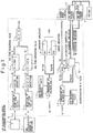
- FIG. 1 is a block diagram showing a first embodiment of the air bag activation control apparatus of the present invention; this embodiment concerns the basic mode for implementing the first method previously described.
- two acceleration sensors are installed which consist of the first acceleration sensor 1 mounted inside the passenger compartment, as in a conventional system, and the second acceleration sensor 2 mounted in the crush zone.
- the crush zone here refers to a space within the vehicle body, located forward of the passenger compartment, and has the effect of mitigating damage to the passenger compartment in the event of a collision by crushing prior to the deformation of the passenger compartment; generally, the forward part of the engine compartment serves as the crush zone.
- Acceleration signals G and G' generated by the acceleration sensors 1 and 2 are coupled via a computation circuit 6 to a reset circuit 20 and two inflator trigger circuit 21 and 22. Each trigger circuit is configured to ignite its associated inflator (not shown) to inflate the air bag 23.
- the acceleration signal G generated by the first acceleration sensor 1 in the passenger compartment is fed to a block 3 which is a computation start point detection circuit; when time t0 at which the acceleration value G exceeds a predetermined acceleration G1 is detected, a prescribed computation based on the acceleration G is started at that point in time.
- the block 4 that follows is a subtracting means which subtracts a predetermined acceleration G2 from the acceleration value G after the computation start time t0 and thereby offsets the acceleration value G to eliminate noise and minute variations in acceleration.
- the decreased acceleration G3 output from the subtracting means 4 is fed into an integrating means 5 which integrates the acceleration G3 over time to compute a first time-integrated value V1.
- the acceleration signal G' generated by the second acceleration sensor 2 mounted in the crush zone is fed to a block 3' which is a computation start point detection circuit; when time t0' at which the acceleration value G' detected by the second acceleration sensor 2 exceeds a predetermined acceleration G1' is detected, a prescribed computation based on the acceleration value G' is started at that point in time, and in the following block 4' which is a subtracting means, a predetermined acceleration G2' is subtracted from the acceleration value G' after the computation start time t0', to compute a decreased acceleration G3', and the acceleration G3' is integrated over time by an integrating means 5' to compute a second time-integrated value V1'.
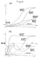
- FIGS. 12(A) and 12(B) are diagrams showing the change over time of the above values V1 and V1': part (A) is a V1-t diagram and (B) is a V1'-t diagram, and the time axis t is shown on the same scale for both diagrams.
- the second time-integrated value V1' based on the second acceleration sensor 2 in the crush zone reaches a greater value at an earlier point in time than does the first time-integrated value V1 based on the first acceleration sensor 1.
- V1' quickly rises to a large value and, likewise, in a high-speed oblique collision, which is also one of the severe collision types, V1' quickly rises in the early stage, as in the high-speed frontal collision; on the other hand, V1 rises slowly during the early stage and, at an intermediate point, begins to rise quickly.
- V1' shows a value higher than that in the low-speed frontal collision from the beginning. In the case of a collision with deer, only a slight change appears in the value of V1, but V1' shows a value as large as a maximum value in the low-speed collision.
- V1 and V1' show similar waveforms between them. This is because no deformation is caused to the vehicle body during rough road driving, causing no appreciable differences due to the mounting position of the acceleration sensors.
- V1' rises earlier than V1
- V1 and V1' show substantially the same waveforms.
- V1' has a tendency to rise earlier than V1, but since the degree of deformation is smaller, the difference is correspondingly smaller.
- first a subtracting means 7 subtracts the first time-integrated value V1, obtained by performing time integration based on the first acceleration sensor 1, from the second time-integrated value V1', obtained by performing time integration based on the second acceleration sensor 2, and thus obtains the difference Vd between the integrated values.
- FIG. 13 is a diagram showing the relationship between the integrated value difference Vd and time t in various types of collision.
- Vd shows large values in the early stages of collision, compared with the temporal change of the first time-integrated value V1 shown in Figure 12(A); furthermore, these values rise quickly with a distinctly recognizable time difference compared with the value for the medium-speed centerpole collision, another collision event that requires air bag inflation.
- the inflator activation mode can be determined in the early stages of collision.
- the inflator activation mode There are two modes for air bag inflation: moderate inflation in which the air bag is inflated at a moderate speed, and rapid inflation in which the air bag is rapidly inflated. Whether the air bag is inflated moderately or rapidly is determined by controlling the number of inflators activated or the activation timing of the inflators, or by controlling both. This will be described below.
- the integrated value difference Vd is fed to a comparator 10 where it is compared with a first time function threshold value Vs1 preset in a block 11 as a threshold value that varies as a function of time; when Vd ⁇ Vs1, it is determined that inflator activation is needed, and an inflator activation instruction signal is sent to the block 15.
- a comparing means 14 compares Vd with a value preset at or near zero (0); if Vd is not larger than the preset value (for example, not larger than zero), the system is reset by the system reset circuit 20, and if Vd is larger than the preset value (for example, larger than zero), the computation in the computation circuit 6 is continued.
- the threshold value Vs1 is set at Th1 higher than the level of the deer collision; with this threshold value level, a severe collision event such as a high-speed frontal or high-speed oblique collision is discriminated in the early stages to issue an inflator activation command.
- Vs1 is set as a gradually decreasing threshold value Th2 downward to the right (decreasing with time) and leading to a lower threshold value Th3 in the remaining stage; using this gradually decreasing threshold value Th2, a moderate-severity collision such as a medium-speed centerpole collision is discriminated to issue an inflator activation command.
- the lower threshold value Th3 in the remaining stage is used to decide whether to activate or not activate the inflators in a low-speed frontal collision event, and is set at such a value that does not trigger air bag inflation in a frontal collision at a speed lower than a predetermined speed.
- the time axis is shown on the same scale as the time axis in the V1-t diagram of Figure 12(A).
- a severe collision such as a high-speed frontal or high-speed oblique collision
- since activation commands can be issued to the inflators in the very early stages of collision not only can the air bag be inflated without delay but, because of increased time margin for the determination of the ignition mode of each inflator, correspondingly longer computation time can be spared for the inflation mode control, increasing the accuracy of the computation for the air bag inflation control.
- the second acceleration sensor 2 is mounted in a position within the crush zone where no deformation is caused in a minor-severity collision such as a low-speed frontal collision, the waveforms of V1 and V1' become substantially the same in the case of low-speed frontal collisions, and the difference Vd can thus be held to a small value. This serves to prevent an erroneous activation in a low-speed collision in a more reliable manner.
- Figure 2 shows a modified example of the first embodiment shown in Figure 1.
- the difference from Figure 1 is that when Vd ⁇ Vs2 as the result of the comparison between the integrated value difference Vd and the second velocity threshold value Vs2 in the comparator 13, elapsed time t' from the starting time t0' of the computation based on the second acceleration sensor 2 is compared in a time comparator 8 with a predetermined first time threshold value ts1 before sending the result to the moderate inflation signal output device 18; then, when t' ⁇ ts1, that is, only when the predetermined time has elapsed, the moderate inflation signal is sent from the block 18 to the block 15, but when the elapsed time is less than the predetermined time (t' ⁇ ts1), the determination of the K value is held off and the computation is continued.
- the configuration is the same; therefore, the same elements are designated by the same reference numerals, and detailed descriptions thereof will not be repeated here.
- Figure 3 shows another modified example of the first embodiment, illustrating an alternative method of determining the inflator activation mode.
- the difference from Figure 2 is that the determination of the inflator activation mode is made not by comparing the integrated value difference Vd with the second velocity threshold value Vs2, but by comparing the second time-integrated value V1' based on the second acceleration sensor 2 with a third velocity threshold value Vs3 preset as a threshold value that varies as a function of time.
- the configuration is the same; therefore, the same elements are designated by the same reference numerals, and detailed descriptions thereof will not be repeated here.
- the second time-integrated value V1' is fed to a comparator 17 where it is compared with the third velocity threshold value Vs3, preset as a function of time, supplied from a block 16, and the inflator activation mode is selected based on the result of the comparison.
- Either activation mode signal is transmitted to the block 15 which, upon receiving the inflator activation signal from the comparator 10, supplies the activation mode signal to the first inflator trigger circuit 21 and/or the second inflator trigger circuit 22, and in accordance with the specified activation mode, the inflators are activated to inflate the air bag 23, as in the case of Figure 2.
- V1' shows higher values than V1 in the early stages of collision.
- Figure 4 shows another embodiment of the present invention.
- the integrated value difference Vd is differentiated in time (d(Vd)/dt) by a differentiator 30 to compute the amount of change, Gd, of Vd, based on which the inflator activation/non-activation decision is made; that is, the amount of change, Gd, of the difference is supplied to a comparator 34 where it is compared with a difference change threshold value Gs preset in a block 32 as a threshold value that varies as a function of time, and a decision whether to activate or not activate the air bag is made based on the result of the comparison.
- a difference change threshold value Gs preset in a block 32 as a threshold value that varies as a function of time
- the difference change threshold value Gd ⁇ Gs
- the comparator 14 compares Vd with the value preset at or near zero (0); if Vd is not larger than the preset value (for example, not larger than zero), the system is reset by the system reset circuit 20, and if Vd is larger than the preset value (for example, larger than zero), the computation in the computation circuit 6 is continued. This operation is also the same as in the foregoing example.
- FIG. 14 is a diagram showing the relationship between the change of amount, Gd, of the difference and time t in various types of collision.
- the threshold value Gs is set at Th10, higher than the level of the deer collision, to prevent an erroneous activation of the air bag in the event of a collision with a deer or the like;
- the high threshold value Th10 is followed by a rightwardly falling steep threshold value Th11 leading to a low threshold value Th12 and, using the threshold value Th11, a severe collision event such as a high-speed frontal or high-speed oblique collision is discriminated in the early stages to issue an inflator activation command.
- a medium-speed centerpole collision can be detected in the early part of the low threshold value Th12 so that the medium-speed centerpole collision can also be detected in the early stages.
- the low threshold value Th12 in the remaining stage is used to decide whether to activate or not activate the air bag in a low-speed frontal collision, and is set at such a value that does not trigger air bag inflation in a collision at a speed lower than a predetermined speed.
- the time axis of Figure 14 is also shown on the same scale as the time axis of the Vd-t diagram of Figure 13.
- the air bag activation command can be issued at an earlier point in time, making it possible to quickly decide to activate the inflators in the event of a severe collision, and allowing a sufficient time margin from the time the activation/non-activation decision is made to the time the inflators are ignited.
- the advantage of this is that a complex computation can be performed for the determination of the air bag inflation mode.
- the determination of the inflator activation mode is made by comparing Vd with the second velocity threshold value Vs2, but it will be appreciated that this can also be accomplished by comparing the second time-integrated value V1' with the third velocity threshold value Vs3 as a time function, as in the example of Figure 3.
- the signal is immediately sent to the block 15, but it will be appreciated that the time comparator 8 and the time threshold value setting device 9 may be included, as shown in Figures 2 and 3, so that the determination of the moderate inflation is held off until the predetermined time ts elapses from the time t0' at which the computation based on the second acceleration sensor 2 was started.
- Vd is compared with the preset value in the comparator 14 and, depending on the result of the comparison, it is determined whether to reset the system or to continue the computation, as in the case of the foregoing embodiment.
- the method that determines that inflator activation is needed when either Vd ⁇ Vs1 or Gd ⁇ Gs is satisfied is the same as the method of Figure 3 or 4, but this has the advantage of making various sensitivity settings possible. Further, the method that activates the inflators only when both conditions are satisfied has the effect of enhancing reliability because the decision is made doubly.
- FIG 6 is a block diagram showing another embodiment of the present invention in which the inflator activation/non-activation decision is made using the first time-integrated value V1 based on the first acceleration sensor 1 in the passenger compartment, in addition to the integrated value difference Vd and the amount of change, Gd, of the integrated value shown in Figure 5.
- a comparator 36 not only compares Vd and Gd with their respective threshold values Vs1 and Gs, but also compares the first time-integrated value V1 with a fourth velocity threshold value Vs4 preset in a block 35 as a threshold value that varies as a function of time, and only when at least one of the conditions of Vd ⁇ Vs1 and Gd ⁇ Gs are satisfied, and the condition V1 ⁇ Vs4 are satisfied, is an inflator activation permit signal sent to the block 15.
- the activation permit signal are input, the block 15 sends the trigger signal to the inflator circuits, as in the case of the foregoing embodiment.
- Vd ⁇ Vs1 the operation is the same as previously described, and therefore, the description will not be repeated here.
- the reason that the first time-integrated value V1 is also used when making the decision is that by setting the fourth velocity threshold value Vs4 for the first time-integrated value V1 at a relatively low value, as shown in Figure 12(A), the decision can, in effect, be made based on Vd and Gd and, at the same time, an erroneous activation due to Vd and Gd can be prevented.
- FIG. 7 is a block diagram showing another embodiment of the present invention, illustrating an alternative method of inflator activation/non-activation decision.
- Vd was compared with the threshold value given as a time function, but the feature of the present embodiment is that Vd is compared with a velocity function threshold value defined as a function of the first time-integrated value V1.
- the comparator 40 compares the two values and, when the integrated value difference is equal to or larger than the fifth velocity threshold value (Vd ⁇ Vs5), sends an inflator trigger permit signal to the block 15.
- Vd is supplied to the comparator 14 where it is compared with a value preset at or near zero (0); when Vd ⁇ 0 (or the preset value near zero), a signal is sent to the system reset circuit 20 to reset the system, but when Vd ⁇ 0 (or the preset value near zero), the computation is continued, as in the case of the foregoing embodiment.
- FIG. 15 is a diagram showing the relationship between Vd and V1 in various types of collision.
- the fifth velocity threshold value Vs5 as a velocity function is hyperbolic in shape; the curve segment a rising along the Vd axis is so set as to be able to discriminate a deer collision, while the minimum value of V1 is set equal to the level of the threshold value Vs4 which is shown as a constant value in Figure 12(A).
- the progressively decreasing curve b along the V1 axis is so set as to be able to discriminate a low-speed frontal collision.
- the threshold value is given, not as a function of time, but as a function of the first time-integrated value V1 so that a stable discrimination result can be obtained independently of time.
- FIG 8 is a block diagram showing another embodiment of the present invention, in which the inflator activation/non-activation decision is made based on the comparison between the amount of change, Gd, of the integrated value difference and the difference change threshold value Gs, in addition to the comparison between the integrated value difference Vd and the fifth velocity threshold value Vs5 as a velocity function shown in Figure 7. That is, in Figure 8, the integrated value difference Vd, the fifth velocity threshold value Vs5, the amount of change, Gd, of the difference, and the difference change threshold value Gs are input to a comparator 43 where the respective comparisons are made, and when either one of the conditions, Vd ⁇ Vs5 or Gd ⁇ Gs, or both conditions are satisfied, the inflator trigger permit signal is sent to the block 15.
- Vd ⁇ Vs5 the system reset circuit 20 is activated to reset the system or the computation is continued, depending on the value of Vd at that time, as in the case of the foregoing embodiment.
- the comparator 45 is also supplied with the second time-integrated value V1' from the integrator 5', the amount of change, Gd, of the difference from the block 30, and the difference change threshold value Gs from the block 32, and compares the second time-integrated value V1' with the sixth threshold value Vs6 set as a velocity function and the amount of change, Gd, of the integrated value difference with the threshold value Gs as a time function of Gd, and when either of the two conditions, Gd ⁇ Gs or V' ⁇ Vs6, or both conditions are satisfied, the inflator activation permit signal is sent to the block 15.
- the decision whether to activate or not activate the inflators can be made based only on the comparison between V1' and Vs6, but the present embodiment shows the case where the decision is made based on two comparisons, that is, one between Gd and Gs and the other between V1' and Vs6.
- V1' ⁇ Vs6 the value of V1' is sent to a comparator 46 where it is compared with the value preset at or near zero (0); if V1' ⁇ 0 (or preset value near zero), a signal is sent to the system reset circuit 20 to reset the system, while if V1' ⁇ 0 (or preset value near zero), the computation is continued. That is, in Figures 1 to 8, the decision whether to reset the system or to continue the computation was made based on the value of Vd at that time, but in the present embodiment, the decision is made based on the value of V1'. Whether to use Vd or V1' is at the designer's discretion, and whichever easier in system design should be chosen. This means that the decision whether to reset the system or to continue the computation can also be made based on the value of Gd at that time.
- FIG. 16 is a diagram showing the relationship between V1' and V1 in various types of collision.
- V1' V1
- Figures 12(A) and 12(B) in every collision type, V1' shows a higher value than V1 from the instant of collision, and has the characteristic of approaching V1 as the time elapses; accordingly, all the lines are located above the 45-degree line.
- the sixth velocity threshold value Vs6 set as a function of V1 is shown in the form of a hyperbolic function of V1 located between the 45-degree line and the V1' axis, and the smallest V1 value on the curve c along the V1' axis is set at a value approximately equal to the level of the threshold value Vs4 shown as a constant value in Figure 12(A) so that a deer collision can likewise be discriminated.
- the curve segment d along the 45-degree line is so set as to be able to discriminate a low-speed collision.
- the threshold value is given, not as a function of time, but as a velocity function of the first time-integrated value V, a stable discrimination independent of time can be achieved, as in the case of the foregoing embodiment that uses the fifth velocity threshold value Vs5.
- FIG 10 is a block diagram showing another embodiment of the present invention, illustrating yet another example of inflator activation/non-activation and inflator activation mode determination.
- the activation mode thus determined can no longer be changed.
- the activation mode if too much emphasis is placed on the optimization of the activation mode, there arises the possibility of missing the inflator activation timing.
- the first inflator is immediately activated while allowing the computation to continue for the inflator activation mode determination; then, if the activation mode determination changes to the rapid inflation mode as the result of the computation, the second inflator is immediately activated.
- the inflator activation/non-activation decision system operates as follows: first, a block 51 checks the activation status of the first inflator, and if the first inflator is in a non-activated state, the block 10 compares the integrated value difference Vd with the first velocity threshold value Vs1 to decide whether to activate or not activate the inflator; if it is determined that there is a need to activate the inflator, the resultant signal is sent to the block 15.
- the inflator activation mode is the moderate inflation mode
- only the first inflator is activated in accordance with the moderate inflation signal, while allowing the computation to continue for the inflator activation mode determination.
- the various threshold values must be chosen so that the determination of the inflator activation mode is completed before the decision is made as to whether to activate or not activate the inflators, but it is difficult to satisfy all such conditions for all types of vehicle body structure and all types of collision.
- the method of the present embodiment that waits the decision to switch or not switch to the rapid inflation mode until the last moment after activating the inflator for moderate inflation, not fixing the inflator activation mode once determined, is a versatile method that can be applied to extensive types of body structure and a variety of collision types.
- Figure 11 is a block diagram showing a modified example of the embodiment of Figure 10. Differences from Figure 10 are that the inflator activation/non-activation decision is made by comparing the amount of change, Gd, of the integrated value difference with its threshold value Gs, and that the blocks 8 and 9 are omitted that were used in Figure 10 to hold off the determination of the moderate inflation mode until the predetermined time elapses after the start of the computation based on the second acceleration sensor.
- the configuration is the same as that of Figure 10; that is, as in the case of Figure 10, when it is determined that there is a need to activate the inflator in the moderate inflation mode, the first inflator is immediately activated while allowing the computation to continue for the inflator activation mode determination, and when the inflator activation mode switches to the rapid inflation mode as the result of the computation, the second inflator is immediately activated.
- the second acceleration sensor is mounted in the crush zone to supplement the first acceleration sensor mounted, as in a conventional system, in the passenger compartment, the most notable feature being that the decision to activate or not activate the inflators and the determination of the inflator activation mode are made based on the differences in characteristics among the integrated values, the difference between the integrated values, the amount of change of the integrated value difference, etc. arising from the differences between the acceleration values detected by the respective sensors in various types of collision.
- Specific implementations of the method have been described with reference to Figures 1 to 11, but it will be appreciated that the present invention is not limited to the illustrated examples, but that various other modifications are possible without departing from the spirit and scope of the present invention.
- the first to fourth velocity threshold values Vs1 to Vs4 may include a constant-value threshold value as a special case of the time function, and the difference change threshold value Gs, also given as a function of time, may likewise include a constant-value threshold value.
- time function threshold values Vs3, Vs1, and Gs given in Figures 12(B), 13, and 14 and each shown as consisting of three straight line segments, can each be represented by a curved line varying as a function of time; conversely, the velocity threshold values Vs5 and Vs6 given in Figures 15 and 16, each shown as a curve varying as a function of the first time-integrated value V1, can each be replaced by a combination of straight lines representing the function of V1.
- the inflator activation mode is determined by comparing Vd with the threshold value Vs2 as a time function of Vd, but this can also be accomplished by comparing the second time-integrated value V1' with the third velocity threshold value Vs3, a time function of V1', as practiced in the example of Figure 3.
- the time-judging circuit may be arranged, for example, between the K value discriminating circuit 15 and the first inflator trigger circuit 21 so that the output of the first inflator trigger signal for moderate inflation is held off until the predetermined time elapses.
- the only requirement here is that the inflator activation by the moderate inflation signal be held off until the predetermined time ts elapses, and the same effect can be achieved as long as this requirement is satisfied.
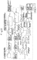
- the block 3 detects the time t0 at which the acceleration value G detected by the first acceleration sensor 1 mounted inside the passenger compartment exceeds the predetermined acceleration G1, and the computation for collision discrimination is started at this time t0.
- a block 4a is a peak-cut means which computes acceleration G3 greater than predetermined acceleration G2 by cutting any acceleration values G after the computation starting time t0 that are not greater than G2 (acceleration not greater than G2 is assumed to be G2).
- a time integrating means 5a integrates the acceleration G3 over time to compute the time-integrated value V
- the velocity subtracting means 5b that follows subtracts a predetermined velocity change value ⁇ V per unit time from the time-integrated value V, as needed, to compute the first time-integrated value V1 as a decreased integrated value.
- the velocity change value ⁇ V may be a constant value or a value of a time function.
- the peak-cut means in the block 4a and the velocity subtracting means in the block 5b provide means for distinctly discriminating between a high-speed oblique collision and a low-speed frontal collision, as described in detail in Japanese Patent No. 2543839 and Unexamined Patent Publication No. 4-321455, and correspond to the offsetting means in the block 4 shown in Figures 1 to 11. Accordingly, the blocks 3 to 5b in Figure 17 provide the same effect as that of the blocks 3 to 5 in Figures 1 to 11, and it will therefore be recognized that either configuration can be used.
- the acceleration signal G' detected by the second acceleration sensor 2 mounted in the crush zone is sent to the block 3' which detects the time t0, at which the acceleration signal G' exceeds the predetermined acceleration G1', upon which the computation for the air bag inflation control is started.
- a block 4a' is a peak-cut means which computes acceleration G3' greater than predetermined acceleration G2' by cutting any acceleration value values G' after the time t0' that are not greater than G2' (acceleration not greater than G2' is assumed to be G2').
- a time integrating means 5a' integrates the acceleration G3' over time to compute the time-integrated value V', and the velocity subtracting means 5b' that follows subtracts a predetermined velocity change value ⁇ V' per unit time from the time-integrated value V', as needed, to compute the second time-integrated value V1' as a decreased integrated value.
- the velocity change value ⁇ V' may be a constant value or a value of a time function.
- the peak-cut means in the block 4a' and the velocity subtracting means in the block 5b' correspond to the offsetting means in the block 4' shown in Figures 1 to 11, as noted above. Accordingly, the blocks 3' to 5b' in Figure 17 provide the same effect as that of the blocks 3' to 5' in Figures 1 to 11, and either configuration may be used, as described above.
- the degree of the collision severity can be determined in the early stages of collision, allowing a time margin for the subsequent computation of the air bag inflation mode; since the computation of the inflation mode is completed by the time it is determined that air bag inflation is needed, the air bag can be immediately inflated without any time delay due to the computation for the inflation mode control.
- the first time-integrated value V1 (either the time-integrated value V before the subtraction or the decreased integrated value V1 obtained by subtracting ⁇ V from it may be used, but in the following description, the value is represented by V1 unless otherwise stated) is compared in a block 62 with a seventh threshold value Vs7 given as a time function, and when V1 ⁇ Vs7, the resultant signal is sent to the comparator 46; if V1 is equal to or smaller than the value preset at or near zero (V1 ⁇ 0), a signal is sent to the system reset circuit 20 to stop the computation, otherwise (V1 > 0) the computation is continued.
- the trigger signal is issued to both the first inflator trigger circuit 21 and the second inflator trigger circuit 22 to ignite the two inflators together, thereby rapidly inflating the air bag 23.
- the block 15 is configured to issue the trigger signal to the inflator trigger circuit(s) 21, 22 only when both the inflator activation signal from the comparator 62 and the inflator activation mode signal from the block 18 or 19 are input, and not to issue the trigger signal when only one or the other of the signals is input. This arrangement is the same as that in the previously described configuration.
- the two inflators are activated either simultaneously or by displacing the ignition timing only slightly.
- One way to ignite the inflators by displacing the ignition timing is to preset ignition timings appropriate to the slow and rapid inflation modes, respectively, and to ignite the inflators with the preset timing difference.
- the ignition timing difference may be determined based on the time, after the starting of the computation, at which the first time-integrated value V1 exceeds the seventh velocity threshold value Vs7, the time function, when V1 is compared with Vs7 in the block 62; that is, when V1 exceeded Vs7 in the very early stages of collision, this means a severe collision and, therefore, the ignition timing difference between the inflators is made small, and when V1 exceeded Vs7 in relatively early stages after that, the inflators are ignited with a slightly larger time difference, for example, with a time difference of a few milliseconds.
- Figure 18 shows another embodiment of the present invention, wherein the same constituent elements as those in Figure 17 are designated by the reference numerals.
- the second time-integrated value V1' obtained in the subtracting means 5b' is input to an inflator trigger determination computing circuit 70 which, based on the second time-integrated value V1, makes a first decision as to whether to activate or not activate the inflators; then, based on the result of this decision, the value of the seventh velocity threshold value Vs7 in the block 71 is varied, and this varied seventh velocity threshold value Vs7 is input to the comparator 62 for comparison with the first time-integrated value V1.
- the crush zone is the first part that is damaged in the event of a collision
- the acceleration detected by the second acceleration sensor 2 settles down earlier than the acceleration detected by the first acceleration sensor 1 mounted, as in a conventional system, inside the passenger compartment, as can be seen from Figure 12. Therefore, if the decision as to whether to activate or not activate the inflators is made based on the acceleration signal from the second acceleration sensor 2, the activation/non-activation decision can be made earlier than would be possible if the decision were made based on the signal from the first acceleration sensor mounted, as in a conventional system, inside the passenger compartment.
- the first decision as to whether to activate or not activate the air bag system is made in the block 70 by using the second time-integrated value V1' computed based on the change of the acceleration detected by the second acceleration sensor 2.
- Various systems (algorithms) proposed in the art and implemented in practice for making such decisions using an acceleration signal from a passenger compartment acceleration sensor can be used for the decision making circuit in the block 70; though not specifically limited, it is preferable to use the algorithm previously proposed by the applicant of the present invention and implemented in practice (the algorithm described, for example, in Japanese Patent No. 2543839 and Unexamined Patent Publication No. 3-253441).
- the comparator 62 compares the first time-integrated value V1 with the seventh velocity threshold value Vs2, and when V1 ⁇ Vs7, the first inflator and/or the second inflator are ignited in accordance with the K value supplied as a slow/rapid inflation indicator to the block 15, as in the case of Figure 17.
- Figure 19 shows a modified example of Figure 17, wherein the same constituent elements as those in Figure 17 are designated by the same reference numerals and will not be described in detail here.
- the second time-integrated value V1' is constantly compared with the first velocity threshold value Vs8 used to judge the severity of the collision
- the degree of the collision severity is determined in the very early stages of the collision, as can be seen from Figure 12(b).
- Figure 19 shows the method that solves the above problems.
- the elapsed time t' from the starting of the computation is compared in a time comparator 65 with a second time threshold value ts2 preset in a block 64, and when t' ⁇ ts2, the inflator activation mode determination by the comparator 60 is held off. That is, even when the computation based on the acceleration sensor 2 is started, the signal for the inflator activation mode determination is not sent to the comparator 60 but the computation is continued until the predetermined second time threshold value ts2 is reached.
- this arrangement serves to prevent a collision that causes an input of a large abrupt acceleration, as described above, or an impact applied during rough road driving, from being erroneously judged as being a severe collision, and thus the stability of the collision severity discrimination is increased.
- the second time-integrated value V1' is sent to the comparator 60 for comparison with the eighth velocity threshold value Vs8; here, the slow or rapid inflation K value may be set in the block 18 or 19 based on the result of the comparison, as in the case of Figure 17, but in the present embodiment, an additional step is included in the activation mode determination process.
- the second time threshold value ts2 may be set at the same value as the first time threshold value ts1 previously explained in the examples of Figures 2, 3, and 10.
- the first time-integrated value V1 is compared with the seventh velocity threshold value Vs7 to decide whether to activate or not activate the inflators, as in the foregoing example, and when it is determined that inflator activation is needed (V1 ⁇ Vs7), the inflator activation signal is sent to the block 15 which, when both the inflator activation signal and the inflator activation mode signal from the block 18 or 19 are input, issues the trigger signal to the inflator trigger circuit(s) 21, 22, as in the foregoing example.
- the inflator activation mode is determined using the second time-integrated value V1' in conjunction with the first time-integrated value V1; this prevents an erroneous determination from being made in such situations as bottom hitting over a rough road that causes a large acceleration change only in the second time-integrated value or a low-speed collision against a thin pole that causes a localized deformation to the acceleration sensor mounting part.
- the effect of this is improved stability in the inflator activation mode determination.
- Figure 20 shows a modification of the example of Figure 19, wherein the same constituent elements as those in Figure 19 are designated by the same reference numerals and will not be described in detail here.
- the 11th velocity threshold value Vs11 in the block 68 is, therefore, set at a large value sufficient to prevent an erroneous activation.
- Figure 21 shows a new embodiment wherein the concept of the time threshold value comparison shown in Figures 19 and 20 is applied to the method of Figure 17.
- the computation is allowed to continue, regardless of the presence or absence of the inflator activation/non-activation decision signal from the block 62.
- Figure 22 shows still another embodiment of the present invention.
- the inflator activation/non-activation decision is made based on the first time-integrated value V1, but the method of Figure 22 significantly differs in that the second time-integrated value V1' is also used for the inflator activation/non-activation decision.
- the illustrated method is the same in that the inflator inflation mode is determined by comparing the second time-integrated value V1' with the eighth velocity threshold value Vs8, but fundamentally differs in that the second time-integrated value V1' is also sent to a comparator 72 where it is compared with a ninth velocity threshold value Vs9 supplied from a block 73, to determine whether to activate or not activate the inflator(s).
- the resultant signal is sent to a comparator 74; if the second time-integrated value V1' is smaller than the value preset at or near zero (0), a signal is sent to the system reset circuit to reset the system, but if V1 is equal to or larger than the preset value, the computation is continued.
- the ninth velocity threshold value Vs9 (V1) used in the present embodiment and the second time-integrated value V1' will be described with reference to the previously given Figure 16.
- the ninth velocity threshold value Vs9(V1) as a function of V1 is set as a hyperbolic function of V1 located between the 45-degree line and the V1' axis, and its value is also set at approximately the same level as the sixth velocity threshold value Vs6; that is, the smallest V1 value on the curve c along the V1' axis is set as a value slightly higher than the level of the deer collision shown in Figure 12(A), while the curve d along the 45-degree line is so set as to be able to discriminate the low-speed frontal collision.
- the threshold value as a function of the first time-integrated value V1, not as a function to time, stable discrimination not dependent on time can be expected.
- Figure 23 shows a modification of the example of Figure 19, wherein the same constituent elements as those in Figure 19 are designated by the same reference numerals and will not be described in detail here.
- the activation mode thus determined can no longer be changed.
- too much emphasis is placed on the optimization of the activation mode, there arises the possibility of missing the inflator activation timing.
- the value of the first time-integrated value V1 is sent to a block 75 which then checks whether the first inflator is activated or not; if the first inflator is not activated, the block 62 compares V1 with the seventh velocity threshold value Vs7 to make a decision as to whether to activate or not activate the inflator.
- the first time-integrated value V1 is also in the process of accumulating by time integration, the value is still below the threshold value Vs7, therefore, it is determined that V1 ⁇ Vs7, and the signal is sent to the block 46; here, if V1 ⁇ 0, the system is reset to stop the computation, as previously described, but when V1 > 0, the computation is continued. As the computation continues, the first time-integrated value V1 increases with time, and when V1 ⁇ Vs7, the inflator activation signal is sent to the block 15.
- the block 76 immediately sends a trigger command signal to the second inflator trigger circuit 22 to ignite the second inflator, and the air bag is thus rapidly inflated with a large amount of gas, combining the gas released from the first inflator with the gas released from the second inflator.
- the value of the eighth velocity threshold value used for the inflator activation mode determination and the value of the seventh velocity threshold value used for the inflator activation/non-activation decision are selected so that the inflator activation mode determination in the block 60 is completed earlier than the inflator activation/non-activation decision in the block 62, but it is not possible to satisfy such conditions for all types of vehicle body structure and all types of collision.
- the method of the present embodiment that considers the possibility of rapid inflation becoming necessary, rather than fixing the inflator activation mode once determined, is a versatile method that is substantially unaffected by the vehicle body structure and that can be applied to extraordinary collision types as well.
- Figure 24 is a block diagram showing a modified example of the method of Figure 23, in which the output of the block 60 that determines the inflator activation mode is directly fed to the block 15, while the inflator activation/non-activation decision based on the first time-integrated value V1 is made using one of two routes according to the activation status of the first inflator.
- the first time-integrated value V1 is first sent to the block 75 that judges the activation status of the first inflator, but in the early stages immediately after the collision, since the first inflator is not activated, the value is sent to the block 62 for comparison with the seventh velocity threshold value Vs7, as in the foregoing example, and when the value reaches or exceeds the threshold value, it is determined that inflator activation is needed, and the signal is sent to the block 15.
- the first time-integrated value V1 is now sent to a block 77, the other inflator activation/non-activation decision device, and compared with a 12th velocity threshold value Vs12 preset in a block 78.
- the 12th velocity threshold value Vs12 is set at a higher value than the seventh velocity threshold value Vs7 supplied to the block 62.
- the trigger signal is immediately sent to the second inflator trigger circuit 22 to activate the second inflator, and thus the air bag is rapidly inflated with a large amount of high-pressure gas combining with the gas released from the earlier ignited first inflator.
- V1 ⁇ Vs12 the value is sent to the block 46 where a decision is made as to whether to continue or not continue the computation, as in the foregoing example.
- the activation mode can be switched to the rapid inflation mode in the second inflator activation/non-activation decision process using the 12th velocity threshold value Vs12; this ensures stable switching from the moderate to the rapid inflation mode, regardless of the type of vehicle body structure or the type of collision, and occupant safety can thus be enhanced.
- the decision whether to activate or not activate the inflators and the determination of the inflator activation mode are made utilizing the differences in output characteristics between the first time-integrated value V1 based on the acceleration signal from the first acceleration sensor mounted inside the passenger compartment and the second time-integrated value V1' based on the acceleration signal from the second acceleration sensor mounted in the crush zone; it will be appreciated, however, that the method of the invention is not limited to the specific examples illustrated in Figures 17 to 22, and that various modifications may be made in accordance with the spirit of the claims appended hereto.
- the concept of the time threshold value shown in Figures 19 to 21, that is, the concept of holding off the activation mode determination for the designated inflator during the predetermined period of time, can be applied to the configuration of Figures 18 and 22 to 24; furthermore, it will be recognized that the combination of the threshold value for the activation mode determination and the threshold value for the activation/non-activation decision is not limited to the illustrated examples, but various other combinations are possible.
- Each velocity threshold value may be set as a constant value, but it is preferable that each velocity threshold value is set as a function of time so that various types of collision can be easily responded to.
- the above description has dealt with examples in which the decreased integrated value V1 obtained by the subtracting means 5b is used as the first time-integrated value used for comparison in various comparators, but instead, the time-integrated value V obtained by the integrating means 5a may be used as the first time-integrated value.
- V or V1 may be used as the first time-integrated value, but the threshold value must be varied accordingly.
- the time-integrated value V' before the subtraction may be used as the second time-integrated value described in the above description, but in this case also, the threshold value must be varied accordingly.
- a performance difference may be provided between the two inflators; for example, the performance of the first inflator is set at 70% of the total gas output and that of the second inflator at 30%, and control is performed so that in a collision of highest severity, the two inflators are ignited simultaneously, while in a collision of moderate severity, the first inflator is ignited first, followed with a certain delay by the second inflator, and in a collision of low severity, only the first inflator is ignited.
- a single inflator whose housing is partitioned into a plurality of independent combustion chambers, each with an independent igniter and capable of being activated independently, may be used instead of the inflators in the present invention;
- the term "plurality of inflators" used in the present invention embraces all such variations, and it will be appreciated that any type of inflator having a plurality of independently ignitable gas generators can be used in the present invention, regardless of whether they are assembled into one unit or not.
- acceleration sensors are mounted in both the passenger compartment and the crush zone, and the decision whether to activate or not activate the inflators and the determination of the inflator activation mode are made utilizing the differences in characteristics that arise between the computed values of the acceleration signals detected by the two sensors in various types of collision due to the differences in the characteristics of these acceleration signals; this makes it possible to easily discriminate soft crashes, represented by impacts during rough road driving and low-speed collisions, which have been difficult to discriminate with traditional crash detection systems that relay only on the acceleration sensor mounted inside the passenger compartment.
- the waveforms of the two acceleration sensors are substantially the same, and the difference between the time-integrated values of the two signals is therefore extremely small.
- the second time-integrated value V1' itself or the difference Vd between V1' and V1 or the amount of change, Gd, of the difference is compared with a threshold value provided as its time function, so that not only a severe collision such as a high-speed frontal or high-speed oblique collision, but also a medium-speed centerpole collision which the passenger compartment acceleration sensor tends to detect belatedly, can be detected in the very early stages of collision.
- an air bag inflation determination system can be constructed that combines an early discrimination capability with a reliable determination capability.
- the computation is continued by holding off the determination of the mode until a predetermined time elapses; this prevents the moderate inflation mode to be determined too early, and enhances the accuracy of the proper activation mode determination.
- the inflator activation mode is determined as moderate inflation
- an "activation needed" instruction is issued from the inflator activation/non-activation decision making circuit
- a specified number of inflators are immediately activated in accordance with the moderate inflation mode, while allowing the computation to continue for the activation mode determination; thereafter, if the mode switches to the rapid inflation mode, the remaining inflators are immediately activated.
- air bag inflation can be initiated at an early stage, and the air bag inflation speed can be changed to that of rapid inflation depending on the change of the condition thereafter. This offers the effect of enhancing the accuracy of the activation mode control, further ensuring occupant safety.
- an air bag activation/non-activation decision making circuit which makes a decision as to whether to activate or not activate the air bag based on the seating position and posture of the occupant, may be provided immediately before or after the block 15 that issues the trigger signal to the first and second inflators.
- the air bag activation control apparatus is capable of inflating the air bag in an optimum mode according to various types of collision, and is therefore very useful as a vehicle passenger protection apparatus.
Landscapes
- Engineering & Computer Science (AREA)
- Mechanical Engineering (AREA)
- Air Bags (AREA)
Applications Claiming Priority (11)
| Application Number | Priority Date | Filing Date | Title |
|---|---|---|---|
| JP14118797 | 1997-05-16 | ||
| JP1997141187 | 1997-05-16 | ||
| JP28760897 | 1997-10-06 | ||
| JP28760897 | 1997-10-06 | ||
| JP30330397 | 1997-10-20 | ||
| JP30330397 | 1997-10-20 | ||
| JP33780997 | 1997-11-21 | ||
| JP33780997A JP3358021B2 (ja) | 1997-10-20 | 1997-11-21 | エアバッグ装置の作動制御装置 |
| JP36169897 | 1997-12-11 | ||
| JP36169897A JP3358022B2 (ja) | 1997-05-16 | 1997-12-11 | エアバッグ装置の展開制御装置 |
| PCT/JP1998/001448 WO1998051544A1 (en) | 1997-05-16 | 1998-03-30 | Actuation controller for air bag device |
Publications (2)
| Publication Number | Publication Date |
|---|---|
| EP0982199A1 true EP0982199A1 (de) | 2000-03-01 |
| EP0982199A4 EP0982199A4 (de) | 2000-10-04 |
Family
ID=27527614
Family Applications (1)
| Application Number | Title | Priority Date | Filing Date |
|---|---|---|---|
| EP98911107A Withdrawn EP0982199A4 (de) | 1997-05-16 | 1998-03-30 | Bestätigungsvorrichtung für einen luftsack |
Country Status (4)
| Country | Link |
|---|---|
| US (1) | US6330500B1 (de) |
| EP (1) | EP0982199A4 (de) |
| KR (1) | KR100363423B1 (de) |
| WO (1) | WO1998051544A1 (de) |
Cited By (15)
| Publication number | Priority date | Publication date | Assignee | Title |
|---|---|---|---|---|
| EP1024977A1 (de) * | 1997-10-23 | 2000-08-09 | Breed Automotive Technology, Inc. | Aufprallsensorsystem |
| WO2001094163A1 (de) * | 2000-06-08 | 2001-12-13 | Siemens Aktiengesellschaft | Elektrische freigabeschaltung für ein insassenschutzsystem |
| WO2002024489A1 (en) * | 2000-09-19 | 2002-03-28 | Ims Inc. | A crash assessment and classification device |
| WO2002028688A1 (en) * | 2000-10-02 | 2002-04-11 | Toyota Jidosha Kabushiki Kaisha | Apparatus and method for controlling activation of vehicle occupant protecting device |
| WO2001054952A3 (en) * | 1999-10-21 | 2002-07-11 | Siemens Automotive Corp Lp | Distributed electronic acceleration sensing for crash severity recognition |
| EP1258400A2 (de) * | 2001-05-14 | 2002-11-20 | Toyota Jidosha Kabushiki Kaisha | Erkennungssystem der Schwere eines Aufpralls |
| WO2003011653A1 (en) * | 2001-07-24 | 2003-02-13 | Siemens Vdo Automotive Corporation | Vehicle impact detection system and control method |
| DE19955559B4 (de) * | 1998-11-20 | 2004-07-01 | Trw Inc., Lyndhurst | Verfahren und Vorrichtung zur Steuerung einer betätigbaren Rückhaltevorrichtung unter Verwendung von Zusammenstoßschwereindizierung und einen Knautschzonensensor |
| GB2369473B (en) * | 2000-08-25 | 2004-12-15 | Ford Global Tech Inc | Restraint System |
| EP1616758A1 (de) * | 2004-07-12 | 2006-01-18 | Calsonic Kansei Corporation | Kraftfahrzeug-Insassenschutzvorrichtung und Verfahren zur Verwendung desselben |
| WO2006106018A1 (de) * | 2005-04-06 | 2006-10-12 | Robert Bosch Gmbh | Verfahren zur erzeugung eines auslösesignals für insassenschutzsysteme |
| EP1710130A3 (de) * | 2005-04-06 | 2007-11-21 | Fuji Jukogyo Kabushiki Kaisha | Vorrichtung zur Bestimmung eines Kollisionsobjekts |
| US7408668B2 (en) | 1999-01-14 | 2008-08-05 | Fujifilm Corporation | Image data communication system, server system, method of controlling operation of same, and recording medium storing program for control of server system |
| EP1409298B2 (de) † | 2001-07-25 | 2008-12-03 | Continental Automotive GmbH | Einrichtung und verfahren zur auslösung eines insassenschutzmittels in einem kraftfahrzeug |
| EP2058179A3 (de) * | 2007-10-11 | 2013-03-06 | Robert Bosch GmbH | Verfahren und Steuergerät zur Ansteuerung von Personenschutzmitteln bei einem Seitenaufprall für ein Fahrzeug |
Families Citing this family (28)
| Publication number | Priority date | Publication date | Assignee | Title |
|---|---|---|---|---|
| JP3524499B2 (ja) * | 1999-01-07 | 2004-05-10 | シーメンス オートモーティブ コーポレイション | エアバッグ作動事象識別システムおよび方法 |
| US6516278B1 (en) * | 1999-09-16 | 2003-02-04 | Honda Giken Kogyo Kabushiki Kaisha | Vehicle hood operating system |
| US6553294B1 (en) * | 2000-10-16 | 2003-04-22 | Delphi Technologies, Inc. | Dual stage occupant restraint deployment control for motor vehicle |
| US6559557B2 (en) * | 2000-12-20 | 2003-05-06 | Delphi Technologies, Inc. | Error detection circuit for an airbag deployment control system |
| DE10109043C1 (de) * | 2001-02-24 | 2002-07-25 | Bosch Gmbh Robert | Verfahren zur Auslösung wenigstens eines Airbags in einem Fahrzeug |
| JP3695351B2 (ja) * | 2001-05-14 | 2005-09-14 | トヨタ自動車株式会社 | 乗員保護装置の起動装置 |
| JP4451032B2 (ja) * | 2001-09-18 | 2010-04-14 | 本田技研工業株式会社 | 自動二輪車用衝突検出装置 |
| JP3778833B2 (ja) * | 2001-09-19 | 2006-05-24 | トヨタ自動車株式会社 | 衝突形態判別装置 |
| DE10245781A1 (de) * | 2002-10-01 | 2004-04-15 | Robert Bosch Gmbh | Verfahren zur Auslösung eines Rückhaltesystems in einem Fahrzeug |
| DE10246800A1 (de) * | 2002-10-08 | 2004-04-22 | Robert Bosch Gmbh | Vorrichtung und Ansteuerung eines Rückhaltesystems |
| DE10311524A1 (de) * | 2003-03-17 | 2004-09-30 | Robert Bosch Gmbh | Verfahren zur Auslösung von Rückhaltemitteln |
| US8186711B2 (en) * | 2004-08-17 | 2012-05-29 | Robert Bosch Gmbh | Separation of abuse conditions and crash events to control occupant restraint devices |
| US7236865B2 (en) * | 2004-09-08 | 2007-06-26 | Ford Global Technologies, Llc | Active adaptation of vehicle restraints for enhanced performance robustness |
| JP4098295B2 (ja) * | 2004-09-24 | 2008-06-11 | 株式会社ケーヒン | 車両用衝突判定装置 |
| US7370721B2 (en) * | 2004-12-03 | 2008-05-13 | Autoliv Asp, Inc. | Seatbelt tensioning device and method |
| DE102006026239B4 (de) * | 2005-06-07 | 2008-04-17 | Denso Corp., Kariya | Insassenschutzvorrichtung und Verfahren zum Schützen eines Insassen |
| US20070096974A1 (en) * | 2005-10-14 | 2007-05-03 | Siemens Vdo Automotive Corporation | Blending of sensors to produce alternate sensor characteristics |
| AU2008261619B2 (en) * | 2007-06-15 | 2014-08-21 | Crossecom Pty Ltd | A sensing system |
| JP5091881B2 (ja) * | 2008-02-20 | 2012-12-05 | カルソニックカンセイ株式会社 | 衝突検知装置 |
| KR101081070B1 (ko) * | 2009-10-07 | 2011-11-07 | 한국과학기술원 | 전방충돌 가속도 센서에 대한 충돌 신호 처리 장치 |
| JP5699944B2 (ja) * | 2012-01-13 | 2015-04-15 | トヨタ自動車株式会社 | 放電コントローラ及び電気自動車 |
| JP6042308B2 (ja) * | 2013-10-29 | 2016-12-14 | 本田技研工業株式会社 | 車両衝突判定装置 |
| DE102014202666B4 (de) * | 2014-02-13 | 2024-05-23 | Robert Bosch Gmbh | Verfahren und Vorrichtung zum Auslösen zumindest eines Personenschutzmittels eines Fahrzeugs |
| DE102014207626B4 (de) * | 2014-04-23 | 2022-09-15 | Robert Bosch Gmbh | Verfahren und Vorrichtung zum Bestimmen eines Aufprallorts eines Objekts auf einem Fahrzeug |
| DE102016222082A1 (de) * | 2016-11-10 | 2018-05-17 | Robert Bosch Gmbh | Verfahren zur Ansteuerung einer Personen-Schutzvorrichtung |
| CN106864405B (zh) * | 2017-04-14 | 2018-04-13 | 吉林大学 | 一种基于碰撞形态预测的智能安全气囊装置主动调控方法 |
| US10501074B2 (en) * | 2017-06-09 | 2019-12-10 | Robert Bosch Gmbh | Methods and systems for reducing vehicle and animal collisions |
| US11034318B2 (en) * | 2019-06-04 | 2021-06-15 | B/E Aerospace, Inc. | Safety system initiator with electronically adjustable fire time |
Citations (2)
| Publication number | Priority date | Publication date | Assignee | Title |
|---|---|---|---|---|
| US4243248A (en) * | 1977-10-11 | 1981-01-06 | Daimler-Benz Aktiengesellschaft | Air bag system for the protection of the passengers of motor vehicles in case of accidents |
| GB2293681A (en) * | 1994-09-29 | 1996-04-03 | Autoliv Dev | A safety arrangement for a vehicle |
Family Cites Families (11)
| Publication number | Priority date | Publication date | Assignee | Title |
|---|---|---|---|---|
| DE3717427C3 (de) * | 1987-05-23 | 1994-09-01 | Deutsche Aerospace | Aufprallsensor für Kraftfahrzeuge |
| DE3920091A1 (de) | 1989-04-06 | 1990-10-11 | Bosch Gmbh Robert | Sicherheitseinrichtung fuer fahrzeuginsassen |
| JPH03121951A (ja) * | 1989-10-04 | 1991-05-23 | Alps Electric Co Ltd | エアバツグ起動制御装置 |
| JPH03246139A (ja) * | 1990-02-23 | 1991-11-01 | Zexel Corp | 車両安全装置のための制御システム |
| JPH04361163A (ja) * | 1991-06-07 | 1992-12-14 | Takata Kk | 車両衝突検知装置 |
| US5202831A (en) * | 1991-07-09 | 1993-04-13 | Trw Vehicle Safety Systems Inc. | Method and apparatus for controlling an occupant restraint system using real time vector analysis |
| JP3085026B2 (ja) * | 1992-06-22 | 2000-09-04 | トヨタ自動車株式会社 | 車両用エアバッグ装置の作動制御装置 |
| JPH0769171A (ja) * | 1993-09-01 | 1995-03-14 | Sensor Technol Kk | 乗員保護装置 |
| US6070113A (en) * | 1996-06-21 | 2000-05-30 | Automotive Systems Laboratory, Inc. | Hybrid vehicle crash discrimination system |
| US6064928A (en) * | 1997-04-24 | 2000-05-16 | Automation Systems Laboratory, Inc. | Mechanical sensor diagnostic method and system |
| US5997033A (en) * | 1997-11-04 | 1999-12-07 | Delco Electronics Corp. | Adaptive airbag inflation method and apparatus |
-
1998
- 1998-03-30 KR KR1019997010603A patent/KR100363423B1/ko not_active IP Right Cessation
- 1998-03-30 WO PCT/JP1998/001448 patent/WO1998051544A1/ja not_active Application Discontinuation
- 1998-03-30 US US09/423,920 patent/US6330500B1/en not_active Expired - Lifetime
- 1998-03-30 EP EP98911107A patent/EP0982199A4/de not_active Withdrawn
Patent Citations (2)
| Publication number | Priority date | Publication date | Assignee | Title |
|---|---|---|---|---|
| US4243248A (en) * | 1977-10-11 | 1981-01-06 | Daimler-Benz Aktiengesellschaft | Air bag system for the protection of the passengers of motor vehicles in case of accidents |
| GB2293681A (en) * | 1994-09-29 | 1996-04-03 | Autoliv Dev | A safety arrangement for a vehicle |
Non-Patent Citations (1)
| Title |
|---|
| See also references of WO9851544A1 * |
Cited By (25)
| Publication number | Priority date | Publication date | Assignee | Title |
|---|---|---|---|---|
| EP1024977A4 (de) * | 1997-10-23 | 2003-04-09 | Breed Automotive Tech | Aufprallsensorsystem |
| EP1024977A1 (de) * | 1997-10-23 | 2000-08-09 | Breed Automotive Technology, Inc. | Aufprallsensorsystem |
| DE19955559B4 (de) * | 1998-11-20 | 2004-07-01 | Trw Inc., Lyndhurst | Verfahren und Vorrichtung zur Steuerung einer betätigbaren Rückhaltevorrichtung unter Verwendung von Zusammenstoßschwereindizierung und einen Knautschzonensensor |
| US7408668B2 (en) | 1999-01-14 | 2008-08-05 | Fujifilm Corporation | Image data communication system, server system, method of controlling operation of same, and recording medium storing program for control of server system |
| WO2001054952A3 (en) * | 1999-10-21 | 2002-07-11 | Siemens Automotive Corp Lp | Distributed electronic acceleration sensing for crash severity recognition |
| US6540255B1 (en) | 1999-10-21 | 2003-04-01 | Siemens Vdo Automotive Corporation | Distributed electronic acceleration sensing for crash severity recognition |
| WO2001094163A1 (de) * | 2000-06-08 | 2001-12-13 | Siemens Aktiengesellschaft | Elektrische freigabeschaltung für ein insassenschutzsystem |
| DE10028352B4 (de) * | 2000-06-08 | 2006-06-01 | Siemens Ag | Verfahren und Schaltung zum Freigeben der Zündbarkeit von wenigstens zwei getrennt zündbaren Zündstufen in einem Insassenschutzsystem |
| US7048302B2 (en) | 2000-06-08 | 2006-05-23 | Siemens Aktiengellschaft | Electrical release circuit for a passenger protection system |
| GB2369473B (en) * | 2000-08-25 | 2004-12-15 | Ford Global Tech Inc | Restraint System |
| WO2002024489A1 (en) * | 2000-09-19 | 2002-03-28 | Ims Inc. | A crash assessment and classification device |
| WO2002028688A1 (en) * | 2000-10-02 | 2002-04-11 | Toyota Jidosha Kabushiki Kaisha | Apparatus and method for controlling activation of vehicle occupant protecting device |
| US6892122B2 (en) | 2000-10-02 | 2005-05-10 | Toyota Jidosha Kabushiki Kaisha | Apparatus and method for controlling activation of vehicle occupant protecting device |
| EP1258400A3 (de) * | 2001-05-14 | 2003-01-02 | Toyota Jidosha Kabushiki Kaisha | Erkennungssystem der Schwere eines Aufpralls |
| US6647331B2 (en) | 2001-05-14 | 2003-11-11 | Toyota Jidosha Kabushiki Kaisha | Collision severity determining system |
| EP1258400A2 (de) * | 2001-05-14 | 2002-11-20 | Toyota Jidosha Kabushiki Kaisha | Erkennungssystem der Schwere eines Aufpralls |
| US6701238B2 (en) | 2001-07-24 | 2004-03-02 | Siemens Vdo Automotive Corporation | Vehicle impact detection system and control method |
| WO2003011653A1 (en) * | 2001-07-24 | 2003-02-13 | Siemens Vdo Automotive Corporation | Vehicle impact detection system and control method |
| EP1409298B2 (de) † | 2001-07-25 | 2008-12-03 | Continental Automotive GmbH | Einrichtung und verfahren zur auslösung eines insassenschutzmittels in einem kraftfahrzeug |
| EP1616758A1 (de) * | 2004-07-12 | 2006-01-18 | Calsonic Kansei Corporation | Kraftfahrzeug-Insassenschutzvorrichtung und Verfahren zur Verwendung desselben |
| US7546193B2 (en) | 2004-07-12 | 2009-06-09 | Calsonic Kansei Corporation | Vehicle occupant protection apparatus and initiation method to use for vehicle occupant protection apparatus |
| WO2006106018A1 (de) * | 2005-04-06 | 2006-10-12 | Robert Bosch Gmbh | Verfahren zur erzeugung eines auslösesignals für insassenschutzsysteme |
| EP1710130A3 (de) * | 2005-04-06 | 2007-11-21 | Fuji Jukogyo Kabushiki Kaisha | Vorrichtung zur Bestimmung eines Kollisionsobjekts |
| US7587266B2 (en) | 2005-04-06 | 2009-09-08 | Fuji Jukogyo Kabushiki Kaisha | Collision object determination device |
| EP2058179A3 (de) * | 2007-10-11 | 2013-03-06 | Robert Bosch GmbH | Verfahren und Steuergerät zur Ansteuerung von Personenschutzmitteln bei einem Seitenaufprall für ein Fahrzeug |
Also Published As
| Publication number | Publication date |
|---|---|
| EP0982199A4 (de) | 2000-10-04 |
| WO1998051544A1 (en) | 1998-11-19 |
| KR100363423B1 (ko) | 2002-11-30 |
| KR20010012642A (ko) | 2001-02-26 |
| US6330500B1 (en) | 2001-12-11 |
Similar Documents
| Publication | Publication Date | Title |
|---|---|---|
| EP0982199A1 (de) | Bestätigungsvorrichtung für einen luftsack | |
| US6438475B1 (en) | Crash detection system | |
| US5967548A (en) | Safety arrangement | |
| EP0987151B1 (de) | Steuerapparat für eine fahrzeuginsassen-sicherheitsvorrichtung | |
| JP3346472B2 (ja) | 乗員保護装置の起動制御装置 | |
| JP3910293B2 (ja) | サイドエアバッグユニット | |
| US6363308B1 (en) | Satellite crash sensor and method with constant and dynamic thresholds for multi-stage restraint deployment | |
| US6756889B2 (en) | Dual sensor crash sensing system | |
| JP2877145B2 (ja) | 乗員保護装置の制御装置 | |
| JP3695351B2 (ja) | 乗員保護装置の起動装置 | |
| US6701238B2 (en) | Vehicle impact detection system and control method | |
| JP3546212B2 (ja) | エアバッグ装置の展開制御装置 | |
| JP3541211B2 (ja) | エアバッグの作動判断装置 | |
| JP3358021B2 (ja) | エアバッグ装置の作動制御装置 | |
| KR100437244B1 (ko) | 자동차 측면 에어백 시스템 및 그 제어방법 | |
| JP3358022B2 (ja) | エアバッグ装置の展開制御装置 | |
| JP3448633B2 (ja) | エアバッグ装置用インフレータの作動制御装置 | |
| JP2835982B2 (ja) | 車輌用安全装置の作動制御方法 | |
| KR100437245B1 (ko) | 자동차 정면 에어백 시스템 및 그 제어방법 | |
| JP2001039264A (ja) | 乗員保護装置制御装置およびソフトクラッシュ検出方法 | |
| KR0150801B1 (ko) | 차량용 에어백 구속 시스템 | |
| JP2001106020A (ja) | 衝突形態の判定装置および判定方法並びにエアバック装置の起動装置 |
Legal Events
| Date | Code | Title | Description |
|---|---|---|---|
| PUAI | Public reference made under article 153(3) epc to a published international application that has entered the european phase |
Free format text: ORIGINAL CODE: 0009012 |
|
| 17P | Request for examination filed |
Effective date: 19991118 |
|
| AK | Designated contracting states |
Kind code of ref document: A1 Designated state(s): DE FR GB |
|
| A4 | Supplementary search report drawn up and despatched |
Effective date: 20000823 |
|
| AK | Designated contracting states |
Kind code of ref document: A4 Designated state(s): DE FR GB |
|
| RIC1 | Information provided on ipc code assigned before grant |
Free format text: 7B 60R 21/32 A, 7B 60R 21/01 B |
|
| 17Q | First examination report despatched |
Effective date: 20020731 |
|
| GRAH | Despatch of communication of intention to grant a patent |
Free format text: ORIGINAL CODE: EPIDOS IGRA |
|
| RIN1 | Information on inventor provided before grant (corrected) |
Inventor name: SADA, HIROYUKIAUTOLIV JAPAN LTD. IN TSUKUBA Inventor name: ONO, MITSURUAUTOLIV JAPAN LTD. IN TSUKUBA Inventor name: MORIYAMA, HIROSHIAUTOLIV JAPAN LTD. IN TSUKUBA |
|
| STAA | Information on the status of an ep patent application or granted ep patent |
Free format text: STATUS: THE APPLICATION IS DEEMED TO BE WITHDRAWN |
|
| 18D | Application deemed to be withdrawn |
Effective date: 20030701 |