EP0980918A1 - Produktförder- und elektrobeschichtungsvorrichtung - Google Patents
Produktförder- und elektrobeschichtungsvorrichtung Download PDFInfo
- Publication number
- EP0980918A1 EP0980918A1 EP98900423A EP98900423A EP0980918A1 EP 0980918 A1 EP0980918 A1 EP 0980918A1 EP 98900423 A EP98900423 A EP 98900423A EP 98900423 A EP98900423 A EP 98900423A EP 0980918 A1 EP0980918 A1 EP 0980918A1
- Authority
- EP
- European Patent Office
- Prior art keywords
- product
- cathode bar
- jig
- nipping
- ribbonlike
- Prior art date
- Legal status (The legal status is an assumption and is not a legal conclusion. Google has not performed a legal analysis and makes no representation as to the accuracy of the status listed.)
- Withdrawn
Links
Images

Classifications
-
- C—CHEMISTRY; METALLURGY
- C25—ELECTROLYTIC OR ELECTROPHORETIC PROCESSES; APPARATUS THEREFOR
- C25D—PROCESSES FOR THE ELECTROLYTIC OR ELECTROPHORETIC PRODUCTION OF COATINGS; ELECTROFORMING; APPARATUS THEREFOR
- C25D17/00—Constructional parts, or assemblies thereof, of cells for electrolytic coating
- C25D17/06—Suspending or supporting devices for articles to be coated
- C25D17/08—Supporting racks, i.e. not for suspending
-
- C—CHEMISTRY; METALLURGY
- C25—ELECTROLYTIC OR ELECTROPHORETIC PROCESSES; APPARATUS THEREFOR
- C25D—PROCESSES FOR THE ELECTROLYTIC OR ELECTROPHORETIC PRODUCTION OF COATINGS; ELECTROFORMING; APPARATUS THEREFOR
- C25D17/00—Constructional parts, or assemblies thereof, of cells for electrolytic coating
- C25D17/06—Suspending or supporting devices for articles to be coated
-
- C—CHEMISTRY; METALLURGY
- C25—ELECTROLYTIC OR ELECTROPHORETIC PROCESSES; APPARATUS THEREFOR
- C25D—PROCESSES FOR THE ELECTROLYTIC OR ELECTROPHORETIC PRODUCTION OF COATINGS; ELECTROFORMING; APPARATUS THEREFOR
- C25D21/00—Processes for servicing or operating cells for electrolytic coating
- C25D21/10—Agitating of electrolytes; Moving of racks
-
- H—ELECTRICITY
- H05—ELECTRIC TECHNIQUES NOT OTHERWISE PROVIDED FOR
- H05K—PRINTED CIRCUITS; CASINGS OR CONSTRUCTIONAL DETAILS OF ELECTRIC APPARATUS; MANUFACTURE OF ASSEMBLAGES OF ELECTRICAL COMPONENTS
- H05K3/00—Apparatus or processes for manufacturing printed circuits
- H05K3/22—Secondary treatment of printed circuits
- H05K3/24—Reinforcing the conductive pattern
- H05K3/241—Reinforcing the conductive pattern characterised by the electroplating method; means therefor, e.g. baths or apparatus
Definitions
- This invention relates to a product conveying mechanism for an electroplating device adapted to electroplate a thin-wall ribbonlike product such as a printed wiring board or a lead frame, which mechanism nips the product in the upper part thereof, suspends it from the nipped part, and conveys the product laterally through an electrolyte solution held in a tank meanwhile feeding an electric current to the product via the upper part thereof.
- the jig which is generally used for fixing in position a thin-wall ribbonlike product such as a printed wiring board or a lead frame has a construction which is composed of a hanger comprising a polar bar connecting part suspended from a cathode bar and possessed of a cross section of the approximate shape of three sides of a square and a main skeletal part and a rack serving to mount thereon the product suspended from the main skeletal part of the hanger and is adapted to fix the rack to a frame of a rectangular shape and meanwhile keep the boundaries of thin-wall ribbonlike products nipped with a plurality of spring clips attached to the frame.
- These products are generally electroplated by being placed wholly together with the rack in an electrolyte solution.
- This invention has for an object thereof the provision of a product conveying mechanism for an electroplating device which electroplates a thin-wall ribbonlike product such as a printed wiring board given to be plated, which mechanism suspends the product from the upper part thereof nipped with a jig supported laterally movably by a cathode bar and conveys the product laterally in an electrolyte solution held in a tank meanwhile feeding an electric current from the cathode bar via the jig to the product through the upper part thereof.
- the invention is particularly directed at providing a product conveying mechanism which is furnished with a jig of striking originality combining the function of nipping a product and the function of feeding an electric current to the product.
- the jig provided by this invention is intended to allow the attachment and detachment of the thin-wall ribbonlike product to be infallibly attained with ease and ensure infallible supply of an electric current from a cathode bar to the product through the jig serving to nip the product in the upper part thereof.
- Another object of this invention is to provide a product conveying mechanism which is furnished with a product sway preventing means adapted to prevent the thin-wall ribbonlike product from swaying while the product nipped in the upper part thereof with the jig is electroplated as laterally conveyed in the electrolyte solution held in a tank.
- This invention consists in providing a product conveying mechanism for an electroplating device which electroplates a thin-wall ribbonlike product such as a printed wiring board given to be plated, which mechanism suspends the product from the upper part thereof nipped with a jig supported laterally movably by a cathode bar and conveys the product laterally in an electrolyte solution held in a tank meanwhile feeding an electric current from the cathode bar via the jig to the product through the upper part thereof,
- the pressure imparting means mentioned above constitutes the spring pressure for the cathode bar lateral face pressing spring member serving to exert constantly the spring pressure on the upper part of the first contact plate so as to press the cathode bar lateral face contact leaf part of the first contact plate against the one lateral face side of the cathode bar. Further, the pressure imparting means mentioned above can constitute the operating force for an operating pin moved forward and backward via a through hole formed in the supporting member to reach the cathode bar lateral face contact leaf part and consequently allow the cathode bar lateral face contact leaf part of the first contact plate to be pressed against the one lateral face side of the cathode bar.
- the cathode bar lateral face contact leaf part of the first contact plate is enabled to establish strong face contact with the one lateral face side of the cathode bar owing to the provision of the spring member for pressing one lateral face of the cathode bar and further since the cathode bar bottom face contact leaf part of the second contact plate is enabled to establish strong face contact with the bottom face side of the cathode bar owing to the provision of the spring member for pressing the bottom face of the cathode bar, supply of electric current from the cathode bar to the nipping leaf parts of the first contact plate and the second contact plate is infallibly attained through the face contact parts mentioned above.
- this invention for the purpose of preventing the thin-wall ribbonlike product from sway while the product nipped in the upper part thereof with the jig is electroplated as conveyed laterally in an electrolyte solution held in a tank, is directed at providing a product conveying mechanism furnished with a product sway preventing means constructed by forming a depressed guide groove on the bottom part side of the tank interior so as to admit the lower parts of the laterally conveyed ribbonlike products as spaced along the path of conveyance of the ribbonlike products, forming a rectifying box on the bottom part of the tank interior so as to be overlaid by the depressed guide groove, forming in the depressed guide groove along the central track on the depressed bottom wall of the depressed guide groove a draining conduit for allowing the electrolyte solution in the tank to flow into the rectifying box, forming in the rectifying box a baffle plate having a plurality of holes opened therein for uniformizing the pressure distribution in the electrolyte solution flowing in through the draining conduit, and
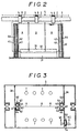
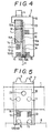
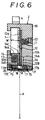
- Fig. 1 through Fig. 3 illustrate wholly the product conveying mechanism for the electroplating device according to this invention and Fig. 4 through Fig. 6 illustrate the jig to be used in the product conveying mechanism.
- the electroplating device of this invention electroplates a thin-wall ribbonlike product A such as a printed wiring board by suspending the product from the upper part thereof nipped with a jig 2 supported laterally movably by a cathode bar 1 and laterally conveying the product A in an electrolyte solution B held in a tank 3 meanwhile feeding an electric current from the cathode bar 1 to the upper part of the product through the jig 2.
- the product conveying mechanism for this electroplating device is composed of the cathode bar 1 having a rectangular cross section and having a difference in the lateral width (W) of the rectangular cross section between the width during the step of releasing the thin-wall ribbonlike product A from the nip and the width during the step of nipping the thin-wall ribbonlike product A, the jig 2 supported laterally movably by the cathode bar 1 and adapted to nip the thin-wall ribbonlike product A in the upper part thereof, suspend the product from the upper part thereof, and feed an electric current to the thin-wall ribbonlike product A through the nipped part thereof, and a conveying means 5 formed of an endless chain furnished with an engaging claw 6 to be meshed with an engaging projection 4 formed on the jig 2 and adapted to move laterally the jig 2 along the cathode bar 1 in consequence of the lateral transfer of the engaging claw 6.
- reference numeral 7 denotes an anode (ball anodes
- the jig 2 mentioned above, as illustrated in Fig. 4 through Fig. 6, is composed of a supporting member 10 made of a synthetic resin and inserted around the cathode bar 1 laterally movably along the cathode bar, a first planar contact plate 12 made of a conductive metal material such as stainless steel and adapted to utilize the upper part side thereof as a contact leaf part 12A allowed to establish face contact with one lateral face side of the cathode bar 1 and urged with the spring pressure exerted by a spring member 11 made of a coil spring on the one lateral face side of the cathode bar and utilize the lower part side thereof as a nipping leaf part 12B adapted to nip the thin-wall ribbonlike product A in the upper part, a second contact plate 14 made of a conductive metal material such as stainless steel and having integrally formed in the shape of the letter L a contact leaf part 14A allowed to establish face contact with the bottom face side of the cathode bar 1 and urged with the spring pressure exerte
- This pressure imparting means constitutes the spring pressure for the cathode bar lateral face pressing spring member 11 serving to exert constantly the spring pressure on the upper part of the first contact plate 12 so as to press the cathode bar lateral face contact leaf part 12A of the first contact plate 12 against the one lateral face side of the cathode bar 1.
- the jig 2 is so constructed as to effect mutual separation of the nipping leaf parts 12B and 14B and consequent release of the thin-wall ribbon product A from the nipping leaf parts 12B and 14B by pressing the cathode bar lateral face contact leaf part 12A of the first contact plate 12 against a gap formed on the one lateral face side of the cathode bar 1 by virtue of the pressure imparting means (the spring pressure of the cathode bar lateral face pressing spring member 11) at the position at which the cathode bar forms a narrowed part of the lateral width (W) and pressing the L-shaped corner part 14C of the second contact plate 14 backward and meanwhile moving the lower part of the first contact plate 12 backward into the vacant place 16 with a stepped part 16A formed at the upper end of the vacant place 16 as a fulcrum.
- the pressure imparting means the spring pressure of the cathode bar lateral face pressing spring member 11
- the aforementioned supporting member 10 made of synthetic resin is composed of a first supporting member 10A for supporting the one lateral face side, the flat face side, and the other upper lateral face side of the cathode bar 1 and a second supporting member 10B supporting the bottom face side and the other lower lateral face side of the cathode bar 1.
- the first supporting member 10A and the second supporting member 10B are fixed by transfixing a clamping bolt 17 having screwed parts 17A and 17B formed in the opposite terminal parts thereof and a shank 17C formed in the middle part thereof across through holes 18 and 19 formed in the nipping leaf parts 12B and 14B of the first contact plate 12 and the second contact plate 14 and causing the screwed parts 17A and 17B to be meshed with screw holes 20 and 21 formed in the first supporting member 10A and the second supporting member 10B.
- the product nipping spring members 15, 15 each made of a coil spring are fitted in a compressed state.
- Reference numeral 22 denotes a blind screw for holding the cathode bar lateral face pressing spring member 11 formed of coil spring in a compressed state in a spring hole.
- the pressure imparting means mentioned above can constitute the operating force for an operating pin (not shown) moved forward and backward via a through hole 23 formed in the supporting member 10 to reach the cathode bar lateral face contacting leaf part 12A and consequently allow the cathode bar lateral face contacting leaf part 12A of the first contact plate 12 to be pressed against the one lateral face side of the cathode bar 1.
- the product sway preventing means denoted by reference numeral 30 in Fig. 1 and Fig. 2 is provided for the purpose of preventing the thin-wall ribbonlike product A from swaying while the product nipped in the upper part thereof with the jig 2 is electroplated by being laterally conveyed in the electrolyte solution B held in the tank 3.
- This product sway preventing means 30 is constructed by forming a depressed guide groove 32 on a rectifying box 31 formed on the bottom part side of the interior of the tank 3 so as to admit the lower parts of the laterally conveyed ribbonlike products A as spaced along the path of conveyance of the ribbonlike products A, forming in the depressed guide groove 32 along the central track on the depressed bottom wall of the depressed guide groove 32 a draining conduit 33 for allowing the electrolyte solution in the tank to flow into the rectifying box 31, forming in the rectifying box mentioned above a baffle plate 34 containing therein a plurality of open holes 35 having a smaller total opening area than the total opening area of the draining conduit 33 so as to uniformize the pressure distribution in the electrolyte solution flowing in through the draining conduit 33, and forming a draining mouth 36 for discharging out of the tank the electrolyte solution which has passed through the baffle plate 34 in the interior of the rectifying box 31, thereby guiding the lower parts of the ribbonlike products A admitted as spaced
- baffle plates 34 By disposing a plurality of baffle plates 34 in a cascade pattern in the rectifying box 31 and causing the total opening area of the holes 35 formed in the baffle plates 34 to decrease in the descending order of the baffle plates 34, it is made possible to disperse the pressure of inflow to a greater extent, allow the electrolyte solution to flow more uniformly into the depressed guide groove 32, and improve the effect of rectification further.
- a product passing means in a tank partition wall denoted by reference numeral 40 in Fig. 3 and Fig. 2 is provided for the purpose of enabling the thin-wall ribbonlike product A conveyed as nipped in the upper part thereof with the jig 2 to acquire smooth passage through an oblong product passing groove 41 formed in a partition wall 3A of the tank 3 so as to pass the partition wall 3A of the tank 3 and, at the same time, preventing the electrolyte solution in the tank 3 from flowing out through the product passing groove 41.
- the product passing means 40 in the tank partition wall is so constructed as to block the product passing groove 41 by forming within the tank 3 a roll regulating frame 42 for enclosing the oblong product passing groove 41 formed in the partition wall 3A of the tank 3 so as to allow passage through the partition wall 3A of the tank 3 of the thin-wall ribbonlike product A conveyed as nipped in the upper part thereof with the jig 2, forming on the product conveying track of the roll regulating frame 42 an inflow groove 43 for allowing inflow of the electrolyte solution in the tank and passage of the product, holding movably inside the roll regulating frame 42 a pair of rolls 44, 44 adapted to sink in an upright state into the electrolyte solution, and utilizing the flowing action of the electrolyte solution in the tank to be discharged from the inflow groove 43 to the product passing groove 41 for moving the pair of rolls 44, 44 from the position indicated by an alternate long and short dash line in Fig. 3 to the position of close contact with the partition wall 3A blocking the product
- the pair of rolls 44, 44 are formed of a plastic material made of vinyl chloride in such a manner that the center of gravity may be caused to occur in the lower parts of the rolls by placing weights in the lower parts of the rolls having a cavity formed in the upper part of roll for the purpose of enabling the rolls to sink in an upright state in the electrolyte solution.
- the size of the jig 2 (excluding the engaging projection 4 mentioned above) is 38 mm in lateral width and 74 mm in height in the bearings of Fig. 5.
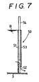
- reference numeral 50 denotes a draining device for adjusting the liquid level of the electrolyte solution B in the tank 3.
- This draining device 50 is constructed by enclosing oblong draining grooves 51 formed on the lateral wall and the partition wall of the tank 3 with a frame 53 having a draining mouth 52 opened in the lower part thereof and inserting a vertically movable adjusting plate 54 in the frame 53 so that the draining mouth 52 mentioned above may be opened and closed by the vertical motion of the adjusting plate 54.
- the vertical operation of this adjusting plate 54 is automatically controlled by a command issued from a liquid level sensor.
- this draining device 50 enables the electrolyte solution to flow out from the middle part of the tank 3, it can decrease the difference between the highest and lowest liquid levels as compared with the device which allows the electrolyte solution to flow out in an overflowing state. Since the difference between the highest and lowest liquid levels can be decreased as described above, the boundary of plating in the partially plated part of the product (the plating treatment performed excepting the upper part of the product) can be uniformized.
- This invention provides a product conveying mechanism for an electroplating device which electroplates a thin-wall ribbonlike product such as a printed wiring board given to be plated by suspending the product from the upper part thereof nipped with a jig supported laterally movably by a cathode bar and conveying the product laterally in an electrolyte solution held in a tank meanwhile feeding an electric current from the cathode bar via the jig to the product through the upper part thereof. It particularly provides a product conveying mechanism which is furnished with a jig of striking originality combining the function of nipping a product and the function of feeding an electric current to the product.
- the jig provided by this invention allows the attachment and detachment of the thin-wall ribbonlike product to be infallibly attained with ease and ensures infallible supply of an electric current from a cathode bar to the product through the jig serving to nip the product in the upper part thereof.
- the product conveying mechanism for the electroplating device according to this invention is furnished with a product sway preventing means, the thin-wall ribbonlike product can be prevented from swaying while the product nipped in the upper part thereof with the jig is electroplated as laterally conveyed in the electrolyte solution held in a tank.
Landscapes
- Chemical & Material Sciences (AREA)
- Engineering & Computer Science (AREA)
- Chemical Kinetics & Catalysis (AREA)
- Electrochemistry (AREA)
- Materials Engineering (AREA)
- Metallurgy (AREA)
- Organic Chemistry (AREA)
- Electroplating Methods And Accessories (AREA)
- Manufacturing Of Printed Wiring (AREA)
Applications Claiming Priority (3)
| Application Number | Priority Date | Filing Date | Title |
|---|---|---|---|
| JP2191897 | 1997-01-22 | ||
| JP02191897A JP3328535B2 (ja) | 1997-01-22 | 1997-01-22 | 電気メッキ装置の製品搬送機構 |
| PCT/JP1998/000177 WO1998032901A1 (en) | 1997-01-22 | 1998-01-19 | Product conveyance mechanism of electroplating apparatus |
Publications (2)
| Publication Number | Publication Date |
|---|---|
| EP0980918A4 EP0980918A4 (de) | 2000-02-23 |
| EP0980918A1 true EP0980918A1 (de) | 2000-02-23 |
Family
ID=12068468
Family Applications (1)
| Application Number | Title | Priority Date | Filing Date |
|---|---|---|---|
| EP98900423A Withdrawn EP0980918A1 (de) | 1997-01-22 | 1998-01-19 | Produktförder- und elektrobeschichtungsvorrichtung |
Country Status (5)
| Country | Link |
|---|---|
| US (1) | US6193863B1 (de) |
| EP (1) | EP0980918A1 (de) |
| JP (1) | JP3328535B2 (de) |
| DE (1) | DE980918T1 (de) |
| WO (1) | WO1998032901A1 (de) |
Families Citing this family (15)
| Publication number | Priority date | Publication date | Assignee | Title |
|---|---|---|---|---|
| US6342138B1 (en) * | 2000-09-01 | 2002-01-29 | M & B Plating Racks Inc. | Clamp for electroplating articles |
| US6521103B2 (en) * | 2001-06-05 | 2003-02-18 | Surface Finishing Technologies, Inc. | Plating clamp assembly |
| JP4746227B2 (ja) * | 2001-09-28 | 2011-08-10 | 秀行 小林 | メッキ装置における製品ガイド機構 |
| FI113280B (fi) * | 2002-04-03 | 2004-03-31 | Outokumpu Oy | Elektrolyysissä käytettävä siirto- ja eristyslaite |
| GB2389370B (en) * | 2002-06-06 | 2006-07-12 | Anopol Ltd | Improvements in stent manufacture |
| US20040007460A1 (en) * | 2002-07-15 | 2004-01-15 | Karl Sagedahl | Clamping device having barbed pin |
| JP5264341B2 (ja) * | 2008-07-23 | 2013-08-14 | 新光電気工業株式会社 | 縦型搬送式めっき装置 |
| JP2011127172A (ja) * | 2009-12-17 | 2011-06-30 | Nitto Denko Corp | めっき装置および配線回路基板の製造方法 |
| KR101038277B1 (ko) * | 2010-12-14 | 2011-05-31 | 주식회사 티케이씨 | 반도체회로 패턴이 형성된 극박형 기판을 위한 비접촉식 도금장치 |
| KR101080896B1 (ko) | 2011-06-10 | 2011-11-07 | 장병원 | 인쇄 회로 기판 제조 공정중 하나인 전기동 도금 라인의 전기동 도금조 내에서 인쇄 회로 기판에 도금액 흐름성을 좋게 하고 인쇄 회로 기판 표면의 동도금을 균일하게 할 수 있도록 한 고정구 |
| JP6448494B2 (ja) * | 2015-07-29 | 2019-01-09 | 株式会社エリアデザイン | サクションめっき装置 |
| US20170145577A1 (en) * | 2015-11-19 | 2017-05-25 | Rohm And Haas Electronic Materials Llc | Method of electroplating low internal stress copper deposits on thin film substrates to inhibit warping |
| CN108004585A (zh) * | 2017-12-01 | 2018-05-08 | 泉州市西决三维科技有限公司 | 一种用于电路板加工的侧夹持旋转电镀机 |
| CN110402034B (zh) * | 2019-07-29 | 2023-01-24 | 吴大伟 | 一种提高pcb图形电镀面均性的方法 |
| CN112342597A (zh) * | 2020-10-15 | 2021-02-09 | 湖州昱日汽车配件有限公司 | 一种用于汽车配件生产用的电镀装置 |
Family Cites Families (7)
| Publication number | Priority date | Publication date | Assignee | Title |
|---|---|---|---|---|
| US4005000A (en) * | 1973-09-17 | 1977-01-25 | National Can Corporation | Electrocoating apparatus and method |
| JPS5921668U (ja) * | 1982-07-29 | 1984-02-09 | 長倉 正次 | 電気メツキ処理装置における被処理物保持材の揺れ防止機構 |
| US4534843A (en) * | 1983-01-28 | 1985-08-13 | Technic, Inc. | Apparatus for electroplating and chemically treating contact elements of encapsulated electronic components and their like |
| JPH0686676B2 (ja) * | 1985-10-18 | 1994-11-02 | 旭化成工業株式会社 | メツキ用電極部 |
| EP0239736B2 (de) * | 1986-02-28 | 1995-10-25 | Schering Aktiengesellschaft | Langgestreckte Gestelle und zugehörige Teile zum lösbaren Befestigen von zu galvanisierenden Leiterplatten, sowie zugehörige Leiterplatten |
| DE19539868C1 (de) * | 1995-10-26 | 1997-02-20 | Lea Ronal Gmbh | Transportvorrichtung und Transportsystem zur vertikalen Führung von plattenähnlichen Gegenständen zur chemischen oder elektrolytischen Oberflächenbehandlung |
| WO1997046740A1 (en) * | 1996-05-30 | 1997-12-11 | M & B Plating Racks Inc. | Holding clamp for electroplating articles in a bath |
-
1997
- 1997-01-22 JP JP02191897A patent/JP3328535B2/ja not_active Expired - Fee Related
-
1998
- 1998-01-19 WO PCT/JP1998/000177 patent/WO1998032901A1/ja not_active Ceased
- 1998-01-19 US US09/341,865 patent/US6193863B1/en not_active Expired - Fee Related
- 1998-01-19 DE DE0980918T patent/DE980918T1/de active Pending
- 1998-01-19 EP EP98900423A patent/EP0980918A1/de not_active Withdrawn
Also Published As
| Publication number | Publication date |
|---|---|
| DE980918T1 (de) | 2000-08-31 |
| US6193863B1 (en) | 2001-02-27 |
| WO1998032901A1 (en) | 1998-07-30 |
| JP3328535B2 (ja) | 2002-09-24 |
| JPH10204691A (ja) | 1998-08-04 |
| EP0980918A4 (de) | 2000-02-23 |
Similar Documents
| Publication | Publication Date | Title |
|---|---|---|
| US6193863B1 (en) | Product conveyance mechanism for electroplating apparatus | |
| US4828654A (en) | Variable size segmented anode array for electroplating | |
| US5516412A (en) | Vertical paddle plating cell | |
| US5514258A (en) | Substrate plating device having laminar flow | |
| US4933061A (en) | Electroplating tank | |
| US4155815A (en) | Method of continuous electroplating and continuous electroplating machine for printed circuit board terminals | |
| US3785474A (en) | Apparatus for sorting and distributing clothing | |
| US4029564A (en) | High speed plating device for rectangular sheets | |
| KR100463807B1 (ko) | 금속스트립의한쪽면내지양쪽면상에의금속내지합금코팅전착장치 | |
| US4832811A (en) | Electroplating apparatus for plate-shaped workpieces, particularly printed circuit boards | |
| TW201003937A (en) | Method and device for producing solar cells | |
| US4986888A (en) | Electroplating apparatus for plate-shaped workpieces | |
| US4425212A (en) | Electroplating device | |
| CN1865520B (zh) | 片状制品的镀覆方法 | |
| KR900018422A (ko) | 도금 시스템(plating system) | |
| WO1996015294A1 (de) | Vorrichtung zur elektrolytischen behandlung von plattenförmigen werkstücken, insbesondere von leiterplatten | |
| JP3065970B2 (ja) | 均一メッキ処理を可能にした電気メッキ処理システム | |
| JPH05209298A (ja) | プリント配線板用電気めっき装置 | |
| NL8502113A (nl) | Werkwijze voor het continu elektrolytisch afzetten van metalen bij hoge stroomdichtheid in vertikale cellen en inrichting voor het uitvoeren van deze werkwijze. | |
| CN116770398A (zh) | 纽扣类用镀敷治具及纽扣类镀敷方法 | |
| JPS6145168Y2 (de) | ||
| US4545884A (en) | High frequency electroplating device | |
| KR20020062642A (ko) | 기판 형태의 작업물, 특히 인쇄 회로 기판을 전해처리하기위한 장치 | |
| KR100515756B1 (ko) | 도금장치의 전극 | |
| AU700448B2 (en) | Anode holder |
Legal Events
| Date | Code | Title | Description |
|---|---|---|---|
| PUAI | Public reference made under article 153(3) epc to a published international application that has entered the european phase |
Free format text: ORIGINAL CODE: 0009012 |
|
| 17P | Request for examination filed |
Effective date: 19990809 |
|
| A4 | Supplementary search report drawn up and despatched |
Effective date: 20000111 |
|
| AK | Designated contracting states |
Kind code of ref document: A4 Designated state(s): DE FR GB IT SE Kind code of ref document: A1 Designated state(s): DE FR GB IT SE |
|
| EL | Fr: translation of claims filed | ||
| DET | De: translation of patent claims | ||
| 17Q | First examination report despatched |
Effective date: 20020426 |
|
| STAA | Information on the status of an ep patent application or granted ep patent |
Free format text: STATUS: THE APPLICATION HAS BEEN WITHDRAWN |
|
| 18W | Application withdrawn |
Withdrawal date: 20020801 |