EP0980523B1 - Appareil de positionnement automatique d'electrodes - Google Patents
Appareil de positionnement automatique d'electrodes Download PDFInfo
- Publication number
- EP0980523B1 EP0980523B1 EP98919082A EP98919082A EP0980523B1 EP 0980523 B1 EP0980523 B1 EP 0980523B1 EP 98919082 A EP98919082 A EP 98919082A EP 98919082 A EP98919082 A EP 98919082A EP 0980523 B1 EP0980523 B1 EP 0980523B1
- Authority
- EP
- European Patent Office
- Prior art keywords
- chamber
- cell
- pipette
- electrode
- image
- Prior art date
- Legal status (The legal status is an assumption and is not a legal conclusion. Google has not performed a legal analysis and makes no representation as to the accuracy of the status listed.)
- Expired - Lifetime
Links
- 0 CCCCCN(C)*C Chemical compound CCCCCN(C)*C 0.000 description 1
Images


Classifications
-
- G—PHYSICS
- G01—MEASURING; TESTING
- G01N—INVESTIGATING OR ANALYSING MATERIALS BY DETERMINING THEIR CHEMICAL OR PHYSICAL PROPERTIES
- G01N33/00—Investigating or analysing materials by specific methods not covered by groups G01N1/00 - G01N31/00
- G01N33/48—Biological material, e.g. blood, urine; Haemocytometers
- G01N33/483—Physical analysis of biological material
- G01N33/487—Physical analysis of biological material of liquid biological material
- G01N33/48707—Physical analysis of biological material of liquid biological material by electrical means
- G01N33/48728—Investigating individual cells, e.g. by patch clamp, voltage clamp
Definitions
- the present invention relates to an apparatus and a method for automatically connecting an electrode to a cell and in particular to an automatic patch clamp apparatus for studying electrical events in cell membranes, such as an apparatus for carrying out patch clamp techniques utilized to study ion transfer channels in biological membranes, and more particularly refers to such patch clamp apparatus having high through-put and utilizing only small test samples of compounds, only small amounts of liquid carrier, and capable of carrying out many tests in a short period of time with an individual membrane patch.
- the invention more broadly refers to a novel electrophysiology drug handling and application set up for screening of chemical substances or compounds, which provides high throughput, and which requires only low volume of solutions and samples to be tested.
- the invention also comprises several methods for utilizing the apparatus of the invention, such as in large scale screening programs in the pharmaceutical industry.
- Ion channels are transmembrane proteins, which catalyze transport of inorganic ions across cell membranes.
- the ion channels participate in processes as diverse as generating and timing of action potentials, synaptic transmission, secretion of hormones, contraction of muscles, etc.
- Many drugs exert their specific effects via modulation of ion channels. Examples are antiepileptic compounds like phenytoin and lamotrigine, which block voltage dependent Na+-channels in the brain, antihypertensive drugs like nifedipine and diltiazem, which block voltage dependent Ca 2+ -channels in smooth muscle cells, and stimulators of insulin release like glibenclamide and tolbutamide, which block an ATP-regulated K+-channel in the pancreas.
- the patch clamp technique has enabled scientists to perform manipulations with voltage dependent channels. These techniques include adjusting the polarity of the electrode in the patch pipette and altering the saline composition to moderate the free ion levels in the bath solution.
- the patch clamp technique represents a major development in biology and medicine, since this technique allows measurement of ion flow through single ion channel proteins, and also allows the study of the single ion channel responses to drugs.
- a thin (app. 0.5-2 ⁇ m in diameter) glass pipette is used. The tip of this patch pipette is pressed against the surface of the cell membrane. The pipette tip seals tightly to the cell and isolates a few ion channel proteins in a tiny patch of membrane. The activity of these channels can be measured electrically (single channel recording) or, alternatively, the patch clamp can be ruptured allowing measurements of the channel activity of the entire cell membrane (whole cell recording).
- the activity of individual channel subtypes can be characterized by imposing a "voltage clamp” across the membrane.
- the "voltage clamp” imposes a voltage gradient across the membrane, and thereby voltage-sensitive channels can be activated.
- a major limitation determining the throughput of the patch clamp technique is the nature of the feeding system, which leads the dissolved compound to perfused cells and patches.
- cells are placed in large experimental chambers (0.2 - 2 ml), which are continuously perfused with a physiological salt solution. Compounds are then applied by changing the inlet to a valve connected to a small number of feeding bottles.
- a number of problems exist in the technique of the prior art.
- the number of different compounds is limited by the number of bottles that may be connected to the application system at one time. This number is usually less than 6.
- the required volumes of the supporting liquid and the sample to be tested are critically high.
- Third, the time needed to change the solute composition around cells and patches is long for usual patch clamp experiments.
- the introduction and application of compounds to be tested usually involves a significant degree of manual manipulation and interruption, thus jeopardizing the integrity of the cell/pipette connection.
- an apparatus for determining the effect of test samples of compounds on ion-transfer channels of a membrane, comprising an autosampler having a plurality of containers adapted to contain test samples in solution, and having means for automatically withdrawing said test samples from each of said containers and discharging them into a receptacle, a container adapted to contain a supporting liquid, a perfusion chamber adapted to receive a test sample in solution, a supporting liquid, and said membrane, said perfusion chamber comprising a reference electrode adapted to contact electrically a solution contained in said chamber, means for transporting said test samples in solution from the receptacle of said autosampler and said supporting liquid from its container into said perfusion chamber, and means for removing said test sample and said supporting liquid from said perfusion chamber, a patch pipette having an electrode therein, movably positioned over said perfusion chamber and adapted to provide a high electrical resistance seal with the surface of a patch of said membrane positioned within said chamber, and means electrically
- US Patent No. US-A-4,907,158 discloses a method for performing work on cells of a cell culture which includes microinjecting cells in the cell culture or drawing liquid from an individual cell or withdrawing whole cells with the aid of suction from the cell culture.
- the system is computer supported and a marker movable in the image on a monitor is superposed on a television image of the cell culture.
- the marker is positioned in the television image on the cell to be injected by the operator by means of a relative movement of the marker with respect to the image.
- the coordinates of the cells marked in this way are stored by the computer which thereafter advances the capillary point automatically to the selected cells and penetrates the latter.
- the computer may guide the penetration movement parallel to the longitudinal axis of the capillary by means of the superposed movement of the object stage and through a superposed movement of the drive for the elevation displacement of the capillary on the micromanipulator.
- an electrode is moved towards one or more cells while an electrical parameter, such as voltage, current, resistance, conductance, inductance, capacitance, etc, is measured in an electrical circuit comprising the electrode and a chamber holding the cells.
- an electrical parameter such as voltage, current, resistance, conductance, inductance, capacitance, etc.
- the parameter changes abruptly and also when the electrode enters a cell the parameter changes whereby contact between the electrode and the cell is detected
- movement of the electrode may be automatically stopped so that the electrode remains in contact with the cell membrane or, the movement may be continued a certain distance to insert the electrode in the internal part of the cell.
- the cell is a macroscopic cell, such as an oocyte, etc
- measurements on the cell is typically performed with two electrodes inserted into the internal part of the cell.
- an automatic electrode positioning apparatus for connecting an electrode to a cell, comprising:
- a method for automatically connecting an electrode to a cell the electrode being contained in a pipette having a pipette tip that is adapted to provide a high electrical resistance seal with the surface of a cell membrane comprising the steps of positioning a chamber for holding cells in an operating position in which connection of the electrode to the cell may be performed, positioning a chamber for holding cells in an operating position in which connection of the electrode to the cell may be performed, positioning the electrode adjacent the chamber in its operating position, determining as electrical parameter in an electrical circuit comprising the electrode and the chamber, and automatically controlling the positioning of the pipette in such a way that the pipette tip is positioned at the determined position of the selected cell and provides a high electrical resistance seal with the cell membrane of the selected cell whereby an electrical parameter of the cell membrane can be determined without intervention of a human operator.
- the apparatus and method of the present invention are capable of automatically connecting an electrode to a cell membrane of an internal part of a cell, e.g. for recording electrical events in cell membranes of cells that are positioned in a chamber.
- the apparatus may comprise selection means for selecting a specific cell to be connected to the electrode.
- the selection means may comprise the measurement means and the controller, the controller being further adapted to continue to control the positioning means so that the electrode scans the chamber with cells until a cell with a parameter within a predetermined range of the parameter is detected whereby that cell is selected.
- the selection means may comprise imaging means for forming an image of cells in the chamber, digitizing means for recording and digitizing the image by dividing the image into pixels, the digitizing means being in operating communication with the imaging means, and a memory for storage of the digitized image and electrically connected to the digitizing means.
- a grey tone image may be represented digitally by a digital image comprising pixels each of which has one pixel value representing the grey tone of the corresponding pixel.
- a colour image may be represented by a digital image comprising pixels each of which has three pixel values, one for each of the colours red, green, and blue.
- the image may be displayed on a display unit, such as a CRT monitor, etc, constituting part of a user interface means of the selection means and an operator may then select a cell to be connected to the electrode, e.g. using a mouse, specific keyboard keys, etc.
- a display unit such as a CRT monitor, etc
- an operator may then select a cell to be connected to the electrode, e.g. using a mouse, specific keyboard keys, etc.
- the selection means may further comprise a processor that is connected to the memory and that is adapted for determination of the position of the selected cell from its position in the image.
- the controller may be electrically connected to the selection means and adapted to receive the position of the selected cell and to automatically control the positioning means in response to the received position in such a way that the electrode is positioned at the determined position of the selected cell.
- the selection of a cell may be performed automatically.
- the processor may be further adapted for processing the digitized image for identification of cells in the chamber, selection of one cell to be connected to the electrode, and determination of the position of the selected cell in the chamber.
- the chamber is typically constituted by a well in a chamber member.
- the cells may be grown on a coverslip, e.g. a 3 millimetre coverslip, which is positioned in the well.
- the chamber is continuously perfused with an appropriate saline solution to prevent cells from drying and dying.
- the chamber for holding cells is also denoted the perfusion chamber or the microperfusion chamber.
- a reference electrode is preferably positioned in the chamber and in contact with liquid in the chamber to facilitate recording of electrical events in a cell membrane of a cell in the chamber.
- the pipette is a patch pipette which typically is a thin (app. 0.5-2 ⁇ m in diameter) glass pipette.
- the tip of the patch pipette is pressed against the surface of the cell membrane.
- the internal volume of the pipette may then be appropriately subjected to negative pressure for the pipette tip to seal tightly to the cell thereby forming a giga-seal between the pipette tip and the cell membrane.
- the pipette has an electrode so that the activity of ion channels of the patched cell membrane can be measured electrically.
- the negative pressure (suction) for the pipette tip may be generated by a modified Eppendorf oocyte injector.
- the injector may be modified to generate output pressures in the range from - 300 hP to + 300 hP in steps of 1 hP with a response time of approximately 10 msec. This fulfils patch clamping requirements.
- the positioning means are adapted to receive and operationally engage with an electrode in a housing or a pipette and to move, preferably in three dimensions, the electrode or pipette to desired positions.
- the positioning means may comprise an electronic micromanipulator, such as a micromanipulator manufactured by Eppendorf.
- the selection means may comprise any sensor suitable for detection of cells.
- the electrode in a chamber with a very large number of cells, the electrode may be used to identify a cell by measurement of conductance between the electrode and the reference electrode of the chamber. When the electrode is lowered into the chamber, the conductance increases when it enters the liquid in the chamber and the conductance decreases again when the electrode connects to a cell membrane.
- a processor may be adapted for identifying cells by monitoring the conductance. In a sufficiently dense population of cells, only a small volume of the chamber need be searched by the electrode to identify a cell membrane by monitoring of the conductance and the first cell identified may be selected, e.g. for patch clamping. In this example, the position of the selected cell is known as the current position of the electrode.
- the processor may comprise any computer such as a standard IBM compatible PC or a computer compatible with an Apple Macintosh (MAC).
- MAC Apple Macintosh
- the selection means may comprise imaging means, such as a microscope, etc, for forming an image of cells in the chamber and positioned adjacent the chamber, digitizing means, such as a hPCCD camera comprising a digital output, a video camera with a frame grabber, etc, for recording and digitizing the image by dividing the recorded image into pixels, each of which has a recorded intensity value, the digitizing means being in operating communication with the imaging means, a memory, such as the memory of a PC, for storage of the digitized image and electrically connected to the digitizing means.
- imaging means such as a microscope, etc
- digitizing means such as a hPCCD camera comprising a digital output, a video camera with a frame grabber, etc, for recording and digitizing the image by dividing the recorded image into pixels, each of which has a recorded intensity value
- the digitizing means being in operating communication with the imaging means
- a memory such as the memory of a PC, for storage of the digitized image and electrically connected to the digitizing means.
- the image may be displayed to an operator of the apparatus, e.g. on a CRT monitor, and the operator may select a cell utilizing a user interface means, such as a mouse, e.g. by moving a cursor with the mouse to a desired cell that may be selected by activation of a mouse button.
- the user interface means may comprise zoom means allowing selection of a specific pixel of the image of the selected cell whereby the corresponding point of the cell surface is selected to be the point of contact with the electrode or pipette.
- the operator may define the position of the tip of the electrode or pipette by moving the cursor to the corresponding position in the image.
- the pixel at the position of the cursor at activation of a mouse button may be selected as the position in the image of the tip of the electrode or pipette.
- the apparatus may automatically move the electrode or pipette to the contact point, e.g. for performing automatical patch clamping.
- the processor is connected to the memory and further adapted for processing the digitized image for identification of cells in the chamber, selection of one cell to be subsequently connected to the pipette or electrode tip, and determination of the position of the selected cell in the chamber.
- the processor may be adapted for processing the digitized image for identification of the pipette or electrode tip, and determination of the position of the pipette or electrode tip.
- Any known and suitable image processing may be utilized to recognize and identify cells and/or the pipette or electrode tip, e.g. comprising edge detecting in order to identify the contour of cells and/or the pipette or electrode tip.
- pixel values are typically stored in an array of memory locations in a digital memory, each memory location corresponding to a pixel of the image.
- a grey tone image may be represented digitally by a digital image comprising pixels each of which has one pixel value representing the grey tone of the pixel.
- a colour image may be represented by a digital image comprising pixels each of which has three pixel values, one for each of the calories red, green, and blue.
- the new pixel value may be calculated from an algorithm, i.e. a spatial digital filter, of the original pixel value and pixel values of neighbouring pixel values, e.g. the new pixel value is the average of the original pixel values of the pixel in question and its eight neighbouring pixels.
- It is presently preferred to identify cells utilizing spatial filtering comprising identifying original pixels and marking, e.g., a corresponding pixel of a new digital image with the same number of pixels as the original image, with a first mark when the original pixel is a pixel onto which a cell has been imaged, i.e. the pixel values of a specific number of neighbouring pixels to the original pixel in question, including the pixel in question, are lower than a selected threshold value.
- the spatial filtering may further comprise identifying and marking with a second mark a group of neighbouring pixels marked with the first mark onto which a single cell is imaged by determining the number of pixels comprised in the group of neighbouring pixels and marking groups having a number of pixels within a predetermined range.
- the spatial filtering may comprise identifying and marking with a third mark a group of neighbouring pixels marked with the second mark if the distance from pixels of the group of neighbouring pixels to pixels marked with the first mark is greater than a predetermined minimum distance.
- the selected cell may be selected among cells that are imaged onto corresponding groups of neighbouring pixels marked with the third mark.
- a set of geometrical parameters are calculated for cells with the third mark, such as maximum cell diameter, cell form factor, cell square extent, etc.
- the value of a selection parameter that is a function of the geometrical parameters is calculated for cells with the third mark and the selection of a cell is made based on calculated selection parameter values. For example the first cell having a calculated selection parameter value within a predetermined range may be selected or, the cell of the cells with the third mark with a selection parameter value closest to a desired value may be selected, etc.
- the selection parameter may be any arithmetic combination of the set of geometrical parameter, such as the product of maximum cell diameter, form factor and square extent.
- the square extent of a cell is calculated by mathematically fitting a square around the cell and calculating the ratio of the number of pixels in the cell to the total number of pixels in the square.
- d max denotes the maximum width of a cell
- A the area of the cell
- the form factor is given by 4 ⁇ ⁇ A C 2 . It is seen that the form factor has a value ranging from 0 to 1 and that the form factor for a circle is 1.
- a predetermined selection parameter range may be determined by manually selecting appropriate cells, e.g. with a mouse and a cursor as described above, and calculating the selection parameter value of the selected cells. Upon selection of an appropriate number of cells, e.g. 25-40, the average and standard deviation of the cells may be calculated and during selection the cell with a parameter selection value closest to the average may be selected. Thus, different types of cells may lead to corresponding different selection parameter ranges.
- the position of the centre pixel of the selected cell may constitute the determined position of the selected cell.
- the signal-to-noise ratio of cell images may be enhanced considerably if the cells are made fluorescent or phosphorescent, e.g. by staining the cells with a fluorescent or phosphorescent dye, by implantation of a gene for a fluorescent or phosphorescent protein, e.g. the enhanced green fluorescent protein (EGFP).
- the imaging means may comprise optical filters for transmission of radiation emitted from the cells and blocking other radiation. This may simplify the cell selection method described above. For example, when EGFP is used, cell selection may be reduced to the steps based on the desired intensity of the green colour marking cells with the first mark, calculating selection parameter values of cells with the first mark, and selecting the cell with the best selection parameter value.
- the processor is adapted to identify pixels onto which the pipette tip or electrode is imaged utilizing spatial filtering of the image.
- the spatial filtering may further comprise identifying and marking with a fourth mark a pixel as a pixel onto which the pipette or electrode tip is imaged when the pixel values of a specific number of neighbouring pixels to the pixel in question, including the pixel in question, are lower than a second threshold value.
- the spatial filtering may comprise identifying a line of pixels, each pixel on the line being positioned at the centre of pixels marked with the fourth mark and being positioned on the line of the pixel in question, and the position of the pipette tip may be determined as the position of an end pixel of the line of pixels.
- test chamber In order to be able to test the influence of various compounds on a cell membrane for hours without intervention of an operator, it is necessary to be able to exchange the test chamber with the cell currently patch clamped with a new test chamber and a new patch pipette so that it is ensured that the test results always can be relied upon.
- the apparatus further comprises a chamber member having a plurality of chambers for holding cells, and chamber member moving means for sequentially moving the chambers from a chamber storage position to the operating position.
- a plurality of test cell cultures are introduced into the respective chambers of the plurality of chambers before performing tests of compounds.
- the cells are grown on a layer of protein on a coverslip that is positioned in a respective chamber prior to testing of compounds.
- operating position means that the positioning means for holding and positioning the pipette and the chamber are positioned in relation to each other in such a way that a selected cell in the chamber can be patch clamped to the pipette tip.
- the chamber member with the chambers may be moved in relation to fixed positioning means or the positioning means may be moved in relation to a fixed chamber member.
- the present apparatus comprises chamber member moving means for moving a chamber from a first storage position in which position the chamber may be supplied with a liquid, e.g. a saline solution, sustaining living cells, to the operating position, and to another storage position when a cell in another chamber is to be patched.
- a liquid e.g. a saline solution, sustaining living cells
- the chamber member moving means may comprise the positioning means as they may be adapted to push and/or pull the chamber member to desired positions.
- the chamber member may comprise a chamber member memory means for storage of data and the apparatus may comprise means for reading the data contained in the chamber member memory means.
- the data may comprise an expiry date of the chamber member, identification data, calibration data, etc.
- the chamber member moving means may be controlled in any known manner.
- This known manner may be a movement controlled by time, length of movement, angle of rotation of the motor shaft, or optical, electrical or mechanical means may be provided for determining when the desired chamber is in its operating position and for terminating the movement
- the chamber member may comprise chambers arranged in a rectangular array of columns and rows of chambers, the chamber member being moved in relation to the positioning means along axis of rows and columns when a new chamber is moved to its operating position, or, the chambers may be arranged in circular arrays, e.g. on a turn-table, the circular array being rotated in relation to the positioning means when a new chamber is moved to its operating position.
- the chamber member may be mounted on a mounting plate which can be moved in an x-y plane by two electromotors and the chamber member may be rotatable, e.g. by a third motor, about an axis perpendicular to the x-y plane so that the individual chambers can be positioned in their respective operating positions by rotation of the chamber member.
- the imaging system may further comprise an inverted microscope forming an assembly with the mounting plate. The position of the focus plane of the microscope may be adjustable thus, facilitating autofocussing prior to initiation of pipette and cell recognition.
- Holders for holding electrodes or pipettes may be positioned with the electrodes or pipettes in an array, e.g. in two rows, on a member that is positioned on the mounting plate.
- the chamber member may further comprise holders for holding pipettes.
- the positioning means may be further adapted to selectively withdraw a pipette from its holder and to insert the pipette into its holder, e.g. when the corresponding chamber is in its operating position.
- the apparatus may further comprise means for supplying liquid, such as a saline solution, to the chambers of the chamber member.
- liquid such as a saline solution
- the means for supplying liquid to the chambers of the chamber member comprises means for supplying a first liquid to the chambers in a storage position and a second liquid to the chamber in the operating position.
- the apparatus may further comprise suction means for removing excess liquid flowing through the chambers.
- the patch clamp technique is combined with the use of an autosampler, a combination which was unobvious at the outset to a person skilled in the art, especially due to the fact that the technique is sensitive to disturbances, such as vibrations and electrical noise arising from the autosampler, so that it would at best have been considered an impossible or inoperative combination.
- the apparatus may be used for automatic drug handling and application, and to utilize the apparatus in an electrophysiological system for screening of chemical substances or compounds to measure their effect on ion channel transfer, the novel system providing high throughput and low fluid volume requirements.
- An apparatus for determining the effect of test samples of compounds on ion-transfer channels of a membrane comprising:
- a microperfusion chamber assembly comprising: a base, an aperture in said base, and transparent means over the bottom of said base, said aperture and said transparent means cooperating to define the side walls and the bottom of a microperfusion chamber, a reference electrode arranged to contact a liquid in said chamber, means for introducing a liquid into said chamber, means for aspirating liquid from said chamber, and means for electrically connecting said reference electrode to an electrical measuring device;
- a microperfusion chamber assembly wherein said transparent means forming the bottom of said chamber is a transparent coverslip;
- said base comprises silver having a coating of a silver halide deposited over at least the surface of the aperture defining the side walls of said microperfusion chamber, thereby providing a reference electrode in said base adapted to make electrical contact with a liquid contained in said chamber;
- said base comprises silver having a coating of silver chloride deposited over at least the surface of the aperture defining the side walls of said microperfusion chamber;
- a method for determining the effect of test samples of compounds on ion-transfer channels of a membrane contained in a perfusion chamber wherein a patch pipette having an electrode therein has its tip engaged in a gigaohm seal with the surface of said membrane, and wherein a reference electrode is provided in said chamber adapted to contact a solution contained in said chamber, comprising:
- the present invention provides apparatus for carrying out patch clamp techniques utilizing an autosampler such as that utilized with HPLC apparatus to provide a very rapid means for carrying out a large number of experiments in a short period of time.
- the invention also permits carrying out patch clamp experiments utilizing only small amounts of test sample and small amounts of supporting liquid.
- the present invention also provides several novel structures for microperfusion chambers capable of supporting patch clamp studies while utilizing only very small amounts of the test samples and very small amounts of supporting liquid.
- the present invention also provides several different procedures for carrying out patch clamp experiments utilizing the novel apparatus.
- the present invention provides a method and an apparatus for automatic recognition of cells and of a pipette tip, facilitating automatic patch clamping and testing of the cells.
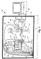
- the assembly of components 10 comprises an air table 12 supporting a Faraday cage 14. Mounted within the Faraday cage 14 is a bridge 16 supporting a table top 18.
- An autosampler 20 (Gilson Model 231 SL), generally used with an HPLC (High Performance Liquid Chromatograph) system, and equipped with a multiple connection valve 22, is mounted on the table top 18, together with a syringe pump 24, and a peristaltic pump 26 (Gilson Model Minipuls 3). Test compounds in solution are contained in sample containers 28, arranged in an autosampler tray 21.
- a needle 30, a component of the autosampler 20, is mounted to be movable both laterally and vertically among the containers 28.
- a rinsing station 23 is provided to collect solution used in rinsing the needle 30.
- An injection port 32 communicates with the multiple connection valve 22.
- the syringe pump 24 is connected to the needle 30 by a duct 40 and, when in operation, causes the needle 30 to draw up a measured volume of liquid from a preselected sample container 28 at a specific position in the autosampler tray 21.
- the needle 30 When the needle 30 has drawn a sample in solution to be tested, it moves to the injection port 32 and injects the sample therein.
- a supporting fluid container 34 adapted to contain a fluid such as a physiological saline solution, is mounted within the Faraday cage 14.
- a waste collection container 36 is also mounted within the Faraday cage 14.
- a plurality of ducts connect the various components of the assembly together for the purpose of transporting fluids among them.
- a duct 38 connects the supporting fluid container 34 to the peristaltic pump 26; a duct 39 connects the supporting fluid container 34 to the syringe pump 24; a duct 40 connects the needle 30 to the syringe pump 24; a duct 42 connects the valve 22 to the waste collection container 36; a duct 44 connects the peristaltic pump 26 to the multiple connection valve 22; a duct 48 connects the injection port 32 to the microperfusion chamber valve 22; a duct 50 connects the rinsing station 23 to the waste collection container 36; and a duct 52 connects the peristaltic pump 26 to the waste container 36.
- an inverted microscope 54 (Nomarski optics, Olympus model IX-70) having a stage 56.
- the microscope itself is attached to the movable part of the table.
- At least one electronic micromanipulator 58 (Eppendorf) is also mounted on the microscope stage 56, and supports a patch pipette electrode holder 60 having mounted there on a preamplifier (headstage) 61 and a conventional patch pipette 62 and which may optionally hold other electrodes for completing voltage and current clamp loops.
- a microperfusion chamber plate 64 is mounted on the microscope stage 56 and includes a microperfusion chamber 72.
- a supply duct 66 connects an outlet from the multiple connection valve 22 to an inlet of the microperfusion chamber plate 64, and a waste duct 68 connects the waste port of the microperfusion chamber plate 64 to a vacuum source for removal of waste.
- the distance from the valve 22 outlet to the microperfusion chamber 72 is 10 cm to minimize the dead-space.
- the electrode within the patch pipette 63 and the reference electrode are both connected to the preamplifier (headstage) 61.
- Electrical wire 76 connects the preamplifier (headstage) 61 to the voltage amplifier 78.
- Electrical wire 77 connects a reference electrode within the microperfusion chamber 72 with the preamplifier (headstage) 61.
- any further voltage or current clamp electrode wires are connected to the amplifier designed to establish the desired current or voltage gradient by the preamplifier (headstage) 61.
- the voltage amplifier 78 is in turn electrically connected to a computer 80 used to measure the electrical impulses indicating the passage of ions through ion channel proteins of the membrane or cell being tested.
- the electronic micromanipulator 58 carrying the patch pipette holder 60 is mounted on the right side of the microscope stage 56.
- valve 22 outlet should be as close as possible to the microperfusion chamber, or to the ti-tube when this component is utilized. Therefore the autosampler itself is placed within the Faraday cage, as shown in Fig. 1, close to the head-stage (preamplifier) 61 of the patch clamp amplifier 78 and the patch pipette 62, which is in contact with the membrane being tested. This raises two potentially serious problems:
- the procedure is carried out by placing a membrane having ion channels into the microperfusion chamber 72.
- the patch clamp procedure may be more conveniently carried out by inserting a small coverslip 74 (2.8 millimetre), on which the cultured cells may be positioned within the microperfusion chamber 72.
- the patch electrode pipette 62 is then lowered into the microperfusion chamber 72 until it comes into contact with the membrane supported on the small coverslip 74.
- Suction is applied to the patch pipette 62 until a giga-seal (giga-ohms) is created between the end of the patch pipette 62 and the biological membrane. Testing is then carried out.
- An electrical signal is detected by an electrode in the patch pipette 62 attached to the preamplifier (headstage) 61, and then is transmitted by electrical wire 76 to the voltage amplifier 78 and the computer 80, shown in Fig. 1.
- a reference electrode (not shown) in contact with the solutions in the chamber is connected to the ground terminal of the preamplifier (headstage) 61.
- a standard solution used for recording of calcium-activated potassium channels comprises (in mM) 140 KCl, 1 CaCl 21 1 MgCl 2 , 1.3 EGTA, 10 HEPES. This composition results in a free calcium concentration in solution of 0.3 ⁇ M. Calcium ion-induced K-channel activation can be achieved by changing the EGTA concentration to 1.07 mM, resulting in a free calcium concentration in solution of 1.0 ⁇ M. Test compounds are dissolved in the supporting solution depending on the protocol of the assay chosen. All test compound solutions and physiological saline solutions are filtered before use in the apparatus.
- a continuous flow of the supporting liquid is established by the peristaltic pump 26.
- the autosampler 20 aspirates a specified volume of test compound from a chosen sample vial 28 and loads it into a tubular loop 70 (total loop filling) via injection port 32.
- the sample volume, loop volume, flow rate, etc. are optional.
- the outlet of the multiple connector valve 22 changes and the loop content is conducted by the duct 66 from the valve to the microperfusion plate into the microperfusion chamber 72 from which excess fluid is removed by aspiration.
- the duration of test compound application is determined by the loop size and the flow rate.
- the wash out time of the compound is optionally determined by the period between injections.
- the autosampler changes chamber solutions automatically according to a predefined program. The number of compounds tested between washout periods varies according to the chosen protocol.
- a physiological saline solution, or other supporting liquid is pumped at a steady rate by the peristaltic pump 26 through the valve 22 and on to the microperfusion chamber 72. Fluid is also continuously aspirated by vacuum from the microperfusion chamber 72 via the duct 68. The procedure continues as follows:
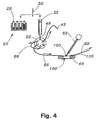
- a modified embodiment of the invention is shown which is utilized to carry out the U-tube technique.
- the components utilized in carrying out the method of this embodiment are substantially the same as those shown in Fig. 1, with the exception that the test sample is discharged into the perfusion chamber 73, through an aperture 83 provided in the bottom of a U-tube 82.
- the peristaltic pump also continuously pumps normal saline through the U-tube 82.
- the fluid is pumped through the multiple connection valve 22 and on to the U-tube through duct 69. Because of the reduced pressure within the U-tube resulting from the fluid flow, a small amount of fluid from the perfusion chamber 73 is aspirated through the aperture 83 into the U-tube.
- a drug sample is loaded into the tubular loop 70.
- the multiple connector valve 22 changes to the injection mode and the tubular loop 70 content is injected into the duct 69 from the outlet port of the multiple connector valve 22 to the U-tube 82.
- the magnetic valve 84 at the outlet of the U-tube 82 is closed, which causes an increase in pressure within the U-tube, thereby forcing a portion of the drug sample through the aperture 83 and into the perfusion chamber 73.
- the valve 84 is reopened, stopping the further flow of the drug sample through the aperture 83.
- the continuous aspiration of the perfusion chamber quickly flushes away the drug sample from the perfusion chamber.
- the application time is optional and determined by the period the valve is closed.
- the use of the U-tube requires a larger experimental perfusion chamber, as shown in Fig. 3.
- the U-tube is placed on 8 separate micromanipulator and positioned under visual guidance from the microscope.
- the advantage of the U-tube system is that it combines the fast application time needed for studying transmitter regulated channels with the high capacity and low volume requirement of the autosampler.
- Fig. 3 shows the flow pattern as it takes place with the U-tube system. This pattern is essentially the same as that in the continuous flow technique, described above.
- saline solution is pumped at a steady rate by the peristaltic pump 26 through a duct 67 from the peristaltic pump 26 to the perfusion chamber 73 (this duct does not pass through the multiple connection valve 22).
- Fluid is also continuously aspirated from the perfusion chamber 73 via duct 68 and the peristaltic pump.
- the peristaltic pump also continuously pumps normal saline through the U-tube 82.
- the fluid is pumped through the multiple connection valve 22 and on to the U-tube through duct 69.
- the general procedure is as follows:
- a somewhat modified arrangement of some of the components is shown for practising the stop flow technique.
- the total volume of the dead space including the injection port 32, the multiple connector valve 22, and the tubing is now particularly critical. Consequently, the tubular loop 70 is replaced with a short straight piece of tubing 86 in order to shorten the path of the test solution and thereby reduce the volume of solution required.
- the volume is reduced to 15 ⁇ l by a special connection of valve inlets and outlets (no loop).
- the operation of the autosampler is somewhat different from that utilized in HPLC autosamplers.
- the general principle is simple, namely, that the autosampler aspirates a specified volume from a sample vial and loads it directly into the microperfusion chamber 100. The process takes place as follows:
- the advantage of the stop flow system is primarily a very low sample volume requirement (maximally 220 ⁇ l total). If less perfusion than around 20 times chamber volume is acceptable, the total volume may be decreased accordingly. Experiments performed according to the present invention indicate that more than 90% exchange is obtained by injecting just 100 ⁇ l (140 ⁇ l total). Such a low volume requirement permits the electrophysiological testing of entire chemical libraries, often based on small amounts of compounds from synthesis and/or isolates from natural products.
- microperfusion chamber assemblies have been developed having extremely small microperfusion chambers.
- the use of these microperfusion chambers provides a system for analysing extremely small volumes of test samples and supporting liquids, thereby greatly reducing the time required for the testing procedure.
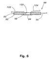
- the chamber assembly 88 comprises a silver disk 90 coated with a thin layer of silver chloride 92.
- the silver disk 90 and the silver chloride layer 92 cooperate to serve as a reference electrode.
- the silver disk 90 has a thickness of 1 mm, and a diameter of 6 mm.
- a 3 mm aperture 94 is bored into the centre of the disk to form the microperfusion chamber 100 cavity.
- a silver wire 96 is soldered to the silver disk 90.
- the silver chloride layer 92 is applied to the surface of the silver disk 90 by placing the silver disk 90 in an aqueous solution of sodium chloride and electrolyzing the disk for 2 hours while it is connected as the anode and utilizing a separate silver wire as the cathode.
- at least the entire surface of the aperture 94 should be coated with silver chloride.
- the entire silver disk 90 is coated with silver chloride, including the surface of the aperture 94.
- a glass coverslip 98, 40 mm in diameter and 0.1 mm thick, is adhesively affixed to the bottom of the coated silver disk 90 and over the aperture 94, to form a transparent bottom of the microperfusion chamber 100.
- the volume of the microperfusion chamber 100 may be in the range of 5-50 ⁇ l. More desirable results may be obtained with a microperfusion chamber 100 in the range of 10-15 ⁇ l, although the preferred range is 10-12 ⁇ l in order to utilize only small samples of the material to be tested and small volumes of supporting liquid, thereby reducing the time required for each test. All solutions enter the chamber through inlet 102 and are aspirated from the chamber through outlet 104.
- Cultured cells may be grown in monolayers on small coverslips 74 (thickness 0.1 mm, diameter 2.6 mm) in a standard incubator. Prior to carrying out the experiments, a single coverslip 74 is transferred by thin forceps to the bottom of the microperfusion chamber 100 and superfused with saline.
- the patch pipette 62 shown in Fig. 1, a standard patch clamp having a final resistance of 2-6 MO, is lowered from above as indicated in Figs. 1, 2, 3, and 4.
- the patch pipette 62 has a silver-silver chloride electrode 63 mounted therein, and is supported by the patch pipette holder 60, a standard type developed by HEKA Electronics.
- the diameter of the pipette tip is about 1 ⁇ m. Consequently, when the pipette is filled by suction, and back-filling, the solution stays in place due to capillary force. Only a slight suction applied by mouth is necessary for creating a giga-seal between the pipette and the membrane used in the testing.
- the electrode 63 contained in the patch pipette 62 is electrically connected to the preamplifier (headstage) 61, which is in turn electrically connected to the patch clamp amplifier 78, which is in turn electrically connected to the computer 80.
- the silver wire 96 is electrically connected to the reference electrode, which comprises the silver disk 90 and the silver chloride layer 92.
- the reference electrode is connected to the silver wire 96, which is in turn electrically connected to the ground terminal on the preamplifier (headstage) 61.
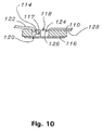
- the assembly 106 comprises a metal sup-25 porting disk 108 designed to fit exactly into the central aperture of the microscope stage 56.
- a microperfusion chamber disk 110 mounted in an aperture provided in the supporting disk 108 is a microperfusion chamber disk 110, shown in detail in Figs. 8 and 9.
- the microperfusion chamber disk 110 may be made of any non-electrically conducting materials, among which are plastics including methyl methacrylate, polystyrene, polyvinyl chloride, phenol formaldehyde, or many other materials.
- An aperture 112 is drilled into the microperfusion chamber disk 110 having a diameter of about 3 mm.
- a groove 114 is provided in the bottom of the microperfusion chamber disk 110 and a coverslip 116 is cemented to the bottom of the disk 110.
- the coverslip 116 cooperates with aperture 112 to form a microperfusion chamber 118.
- the coverslip 116 cooperates with the groove 114 to form a channel 117 for introducing the liquid sample to be tested and the supporting saline solution into the microperfusion chamber 118.
- An aperture 120 is provided in the upper wall of the disk 110 to serve as a port for the introduction of liquids into the channel 117.
- a tube 122 connects the aperture with the autosampler multiple connection valve 22 shown in Fig. 1.
- a small silver/silver chloride pellet electrode 124 is embedded in a groove 126 provided in the upper surface of the disk 110, and serves as a reference electrode.
- the pellet electrode 124 is formed of a mixture of silver and silver chloride compressed around a silver wire, obtained from IN VIVO METRIC, California.
- a wire from the electrode 124 is connected directly to the amplifier headstage 78, shown in Fig. 1.
- Aspiration of excess fluid from the microperfusion chamber such as 72, 100, or 118 represents a special problem with small chambers, since a large fraction of the total chamber volume is aspirated per second.
- a very smooth aspiration with a tiny plastic tube 128 (Eppendorf GELoader Tip) can be utilized and is essential to avoid fluctuations in the level of the liquid surface. Unstable liquid surfaces produce a variable background noise and may also confer an increased mechanical stress to the cell or patch, thereby limiting the recording period.
- the Ca 2+ currents were isolated from other currents by use of the following pipette and bath solutions: Pipette : CsCl (100 mM), CsF (20 UIM), EGTA (10 mM), MgCl 2 (4 mM), HEPES (10 mM). Bath : NaCl (140 mM), KCl (4 mM), CaCl 2 (2 mM), MgCl 2 (1 mM), HEPES (10 mM), TTX (0.3 pM). The high Calcium concentration blocks K+ currents, whereas TTX (tetrodotoxin) blocks Na + currents.
- Pipette CsCl (100 mM), CsF (20 UIM), EGTA (10 mM), MgCl 2 (4 mM), HEPES (10 mM).
- Bath NaCl (140 mM), KCl (4 mM), CaCl 2 (2 mM), MgCl 2 (1 mM), HEPES (10 m
- the (1)-conotoxin MVIIA has a high affinity for N-type calcium channels as demonstrated by the current modulation recorded on the graph.
- the graph also demonstrates that the (i ⁇ -conotoxin MVIIA binding was irreversible because no washout is evident from the graph.
- Bay-k 8644 and nifedipine were injected at 45 minutes and 1 hour respectively.
- Bay-k 8644 stimulates L-type calcium channels reversibly, as is evident from the washout over time.
- Nifedipine blocks the L-type calcium channel.
- the invention is thus demonstrated to be useful in determining the response of patch-clamp isolated membrane ion channels to perfusion with compounds having well-know physiological activity.
- the results indicate that five compounds were tested in little more than one hour using a single membrane preparation, and exhibiting a useful range of physiological response.
- screening of unknown compounds including application periods as well as washout periods between applications are shorter and therefore ten to twenty compounds can be screened in the course of an hour. (See especially Example 2.)
- STOP-FLOW TECHNIQUE The potassium current of a cultured human coronary smooth muscle cell was determined in an excised inside out patch by the stop- flow technique utilizing an apparatus as disclosed above and diagrammed in figures 7-10, comprising an autosampler, syringe pump, and microperfusion chamber having a volume of 12 ⁇ l.
- KCl 140 ZuM
- CaCl 2 1 mM
- MgCl 2 1 mM
- EGTA 0.07 mM to 2.0 mM.
- the free Ca 2+ concentration is determined by the concentration of EGTA. All test compounds were dissolved in bath solution with 0.3 pM free Ca2+.
- the invention is thus demonstrated to provide a mechanism whereby small volumes of test compounds can be analyzed in rapid succession.
- the test is remarkable because over twenty-five (25) unknown test compounds were screened in the course of a two hour time period.
- the test was validated by intermittent full activation of K-channels induced by perfusion with saline solution having a higher free calcium ion concentration. This high calcium induced potassium current demonstrates the scope of current response available from the membrane preparation, evidencing the sensitivity necessary to detect an active compound.
- the present application discloses a novel way of utilizing an HPLC autosampler in carrying out patch clamp techniques. This enables a large number of tests to be carried out in a relatively short time period.
- the application also discloses the use of novel microperfusion chamber assemblies containing very small microperfusion chambers, thereby enabling very small amounts of test sample solutions and supporting solutions to be utilized, and additionally reducing the amount of time required for each test.
- the application also discloses several novel procedures for carrying out the patch clamp technique providing even further benefits.
- the application further includes novel microperfusion chamber structures utilizing very small chambers and having integral electrodes.
- membrane is employed to designate whole cells or partial cell membranes.
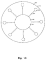
- a turn table 400 comprising several perfusion chambers 202 is shown.
- the turn table 400 comprises three parts, a rotatable outer part 200, a fixed inner part 220 and a top part 246.
- the rotatable outer part 200 has an outer periphery 210, an inner periphery 208 defining an inner volume 206 within the periphery 208, and a plurality of perfusion chambers 202.
- Each of the perfusion chambers 202 is connected to the inner volume 206 through drilled bores 204 in the outer part 200.
- the plurality of perfusion chambers 202 with connecting drilled bores 204 is in a preferred embodiment eight, but fewer, such as four, as well as more, such as sixteen, perfusion chambers 202 may be provided.
- the outer periphery 222 of the inner part 220 is slightly smaller than the inner periphery 208 of the outer part 200, i.e. the inner part 220 fits into the volume 206 of the outer part 200.
- the inner part 220 comprises a milled out grove 228 that communicates with the outer periphery 222 through a plurality of bores.
- the grove 228 has two stop points 230 and 232, as well as a reference electrode 226 connected to the internal of the grove 228 leading to a test perfusion chamber 202'. At the other end, the reference electrode 226 is grounded.
- the top part 246 is a plate with an outer periphery 240 and two holes 242 and 244.
- the periphery 240 of the top plate 246 has the same size as the outer periphery 222 of the inner part 220, but the periphery 240 of the top plate 246 could be made larger or smaller than the outer periphery 222 of the inner part 220, as long as the two holes 242 and 244 are positioned so as to provide connection from the upper side of the top part 246 through the top part 246 to the grove 228 in the inner part 220 when the top part 246 is mounted on the inner part 220.
- the hole 244 in the top part 246 is positioned so as to provide connection from the upper side of the top part 246 through the top part 246 into the grove 228 between the two stop points 230 and 232 and further out to the test perfusion chamber 202' in the other end of the connecting drilled bores 224 and 204.
- the hole 242 provides connection from the upper side of the top part 246 through the top part 246 into the grove 228 and from there to the rest of the perfusion chambers 202 via the drilled bores 204 and 224.
- one solution may be supplied to the test perfusion chamber 202' through the hole 224 and simultaneously another solution may be supplied to the other perfusion chambers 202 through the hole 242 without the two solutions being mixed.
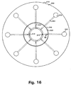
- Fig. 16 the outer part 200, the inner part 220 and the top part 246 have been assembled to constitute the turn table 400.
- the arrows show the direction of flow for the liquid solutions provided to the turn table 400 through the holes 242 and 244.
- test perfusion chamber 202' By rotating the outer part 200 in relation to the inner part 220, the test perfusion chamber 202' may be moved from it's present position to a new position, and at the same time an other perfusion chamber 202 may be moved into the previous position of the test perfusion chamber 202', thereby taking over the function as the test perfusion chamber 202'.
- FIG. 17 another view of the turn table 400 is displayed.
- the outer part 200 of the turn table 400 comprises a plurality of pipette holder supports 250, one pipette holder support 250 for each perfusion chamber 202 in the outer part 200.
- Each of the pipette holder supports 250 is used for holding one pipette holder 260, as shown for half of the pipette holder supports 250.
- a cross section of the turn table 400 is shown.
- the cross section is seen from the point c at the perimeter of the turn table 400 via the centre f to the point d at the perimeter of the turn table 400.
- the path comprising the hole 242, the grove 228, the drilled bore 224 and the drilled bore 204 guides the liquid solution from the hole 242 to the perfusion chamber 202.
- Excessive liquid solution is guided via an overflow grove 203 to a waste chamber (not shown), from where it is removed for disposal through holes (not shown) in the inner part 220 and the top part 246 by a tube connected to a suction pump.
- a detailed view of a pipette holder 260 is displayed.
- the pipette holder 260 comprises three main parts, the upper part 266, the middle part 264, and the lower part 262.
- the lower part 262 comprises a first O-ring 268, a hole 292 for a glass pipette 274, and a first thread 278.
- the middle part 264 comprises a first shoulder 294, a second thread 276 fitting the first thread 278, and a third thread 282.
- the upper part 266 comprises a second shoulder 296, a fourth thread 280 fitting the third thread 282, a second O-ring 270, and first connecting means 302.
- the insertion part 284 When the pipette holder 260 is assembled, the insertion part 284 is inserted into the upper part 266 from below, and the insertion part 284 is hold in place in the upper part 266 by friction. Soldered to the insertion part 284 is an electrode 298 made from silver and with a layer of silver chloride. The upper part 266 is then connected to the middle part 264 by screwing them together using the threads 280 and 282.
- a glass pipe or pipette 274 is inserted into the hole 292 of the lower part 262, and the electrode 298 is inserted into the pipette 274.
- the lower part 262 is then screwed onto the middle part 264 using the threads 276 and 278.
- the glass pipette 274 is pushed up against the lower part of the insertion part 284.
- the first O-ring 268 will seal the opening 292 and fix the glass pipette 274 in it's position.
- the manipulator 300 comprises second connecting means 288 and a terminal 286 connected to a suction pump.
- the first connecting means 302 of the upper part 266 fits into the second connecting means 288 of the manipulator 300 so that when the first connecting means 302 of the upper part 266 is pushed into the second connecting means 288 of the manipulator 300, it is secured in that position by friction between the first connecting means 302 and the second connection means 288.
- the manipulator 300 may also comprise a preamplifier (not shown) for preamplifying the measurement signals obtained during patch clamp.
- the second O-ring 270 provides sealing between the manipulator 300 and the upper part 266 of the pipette holder 260.
- the terminal 286 may be connected to a tube connected to a suction pump. When the pump starts to suck, air or liquid solution will be sucked up through the tiny hole in the tip 290 of the pipette 274.
- the advantage of the pipette holder 260 thus provided is that the necessary vacuum that must be applied at the tip 290 of the pipette 274 may be provided by the second connecting means 288 through the pipette holder 260.
- the pipette 274 and the pipette holder 260 is discarded, and the pipette holder support 250 is connected to another pipette holder 260 with a new pipette 274.
- This procedure may, using the provided pipette holder 260, be performed without the otherwise necessary removal of a suction tube mounted on the pipette holder 260 and thereafter mounting the suction tube on a new pipette holder 260, as the suction tube is mounted on the second connecting means 288 to be reused.
- the pipette holder 260 thus provided is ideal for use in an automatic patch clamp apparatus.
- the pipette holder 260 When not in use, the pipette holder 260 is mounted on the pipette holder support 250. When the manipulator 300 is moved to pick up the pipette holder 260, the second connecting means 288 is pushed against the first connecting means 302 until a frictional engagement is obtained.
- the pipette holder support 250 comprises two engaging parts 310 and 312 engaging with the shoulder 296 of the upper part and the shoulder 294 of the middle part 264, so that when the manipulator 300 pushes against the pipette holder 260, the pipette holder 260 is held in place by the engaging parts 310 and 312.
- the manipulator 300 moves the pipette holder 260 into position in the pipette holder support 250, and when the engaging parts 310 and 312 engages with the shoulders 296 and 294, the first connecting means 302 and the second connecting means 288 may be pulled from each other.
- the outer part 200 may be provided with guide pins 320 positioned on the outer perimeter as shown in Fig 17.
- the manipulator 300 may push against the guide pins 320, thereby rotate the outer part 200 around it's centre f.
- the guide pins 320 may also be positioned on top of the outer part 200 between the pipette holder supports 260, or the pipette holder supports 260 may also be used as guide pins, and in both these cases, the manipulator 300 may push against the guide pins or the pipette holder supports 260 and thereby rotate the outer part 200 around it's centre f.
- one or more of the pipette holders 260 must be equipped with pipettes and positioned in the pipette holder support 250, and the manipulator 300 should be moved to a neutral or resting position.
- the manipulator 300 moves to engage with and pick up a pipette holder 260'.
- the manipulator 300 then moves the pipette holder 260', selected among the plurality of pipette holders 260, to the test perfusion chamber 202' next to the pipette holder 260', where the tip of the pipette is positioned on a chosen cell to be investigated, patch clamp is obtained and the measurement is performed.
- the manipulator 300 moves the pipette holder 260' back to the pipette holder support 250' and the manipulator 300 and the pipette holder 260' are disengaged.
- the manipulator 300 then pushes against the guide pin 320 to rotate the outer part 200 to a new position, whereafter the manipulator 300 may pick up a new pipette holder 260 to start the procedure again.
- the movements of the manipulator 300 may be controlled by a computer, e.g. a standard IBM compatible PC or a computer compatible with an Apple Macintosh (MAC).
- a computer e.g. a standard IBM compatible PC or a computer compatible with an Apple Macintosh (MAC).
- MAC Apple Macintosh
- the manipulator 300 When, as described above, the manipulator 300 has moved the tip of the pipette to the test perfusion chamber 202', the tip should be positioned on a suitable cell.
- the search for a cell to be patch-clamped and the recognition of the tip of the pipette are based on visual (graphics) information in digital images of the objects (cells and pipette).
- the digital images may be recorded by an analog video camera connected to a framegrabber, a digital video camera, a digital camera, etc.
- the same computer that is used to control the manipulator 300 and used as a basis for the framegrabber and the NeuroPatch software, may also be used for acquiring the measurement data during patch clamp, but a separate computer may also be utilized.
- the image that the current implementation of the NeuroPatch software operates on may be obtained from a standard video camera delivering a PAL S-VHS output signal.
- a live image is displayed.
- the live image is frozen and a 256 grey level copy of the frozen image is transferred to an image buffer.
- the recognition routines then operate on the frozen image in the image buffer, but the frozen image will not be changed by the recognition routines. Instead, the results of the recognition routines will be stored in one or more images or image buffers.
- the frozen image 500 comprises a plurality of cells 505 and a pipette 510 with a pipette tip 508.
- the selection of a proper cell for patch clamping may be performed by using the following method.
- the method comprises 5 steps:
- one or more filters are applied on the image. It should be understood that applying a filter on a digitized first image is performed by applying the filter for each pixel one by one in a first image. The result of the filtering is stored in a second image or image buffer in a position corresponding to the pixel in the first image, and after applying the filter for all pixels in the first image, the second image contains the filtered image. This image may then be used for further filtering. A filter may cover more than one pixel in the first image, but the result of the filtering will only be stored in one pixel in the second image.
- a pixel in the first image is designated the centre pixel
- the eight pixels surrounding the centre pixel may be covered by the filter, and the filter therefore in this case uses 9 pixels in the first image to calculate a new pixel value for a pixel in the second image corresponding to the centre pixel in the first image.
- a simple example of a filter using 9 pixels is an averaging or smoothing filter. The average of 9 pixels in a cluster of 3 by 3 pixels in the first image is calculated and stored in the pixel in the position in the second image corresponding to the position of the centre pixel in the first image.
- a specific value of a pixel corresponds to a specific colour (or a specific tone of grey).
- a value of a pixel may therefore be represented by a colour and vice versa.
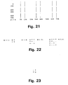
- filters used in the presently preferred embodiment of the invention is displayed.
- the centre pixel is marked with an "x" and the adjacent or neighbouring pixels used in the filter are marked with a "*".
- the filter does not necessarily operate on all the adjacent or neighbouring pixels, and the pixels not used are marked with a "-".
- the original image or the resulting or filtered image may be displayed on a monitor.
- parameters define values to be used when the filters are applied to the image, either for defining parameters of the filters (size, function), or for selecting the pixels in the image to be filtered.
- parameters of the filters size, function
- values of the filters are shown in Table 1, the name, range, and default values for the filters are shown.
- the task of the first step is to convert the 256 grey level image of cells into a binary image comprising pixels having one value of a set of two values. Pixels with a grey level value greater than a calculated threshold value (say lighter pixels) are represented by one value (say the colour white) and pixels with a grey level value less than the threshold value (say darker pixels) are represented by another value (say the colour red).
- m boundsFactor
- Step 1 After Step 1, it is possible to see the outlines of the cells and parts of their interiors.
- the cells should appear as "solid" structures without holes in their interiors. So, in this step an attempt is made to close the holes in the interiors of the cells. The way this is done has the side-effect that small gaps between clusters of cells are also closed. This side-effect later becomes an advantage in the sense that clusters will appear as large structures that will be disqualified due to their size as if it was an artifact.
- Step 2 it is possible to see filled profiles of various sizes. Cells that are positioned closely to each other may appear as a large block of pixels, while cells that are reasonably isolated will appear at their correct sizes. Now, a size filter is applied so that groups of pixels that are smaller than a minimum size or larger than a maximum size are disqualified from further evaluation.
- Step 3 those clusters of pixels that fulfil the size requirements for being cells are marked (blue). Now, further investigation is made to choose those clusters that have a proper degree of isolation for further evaluation.
- Step 4 those clusters of pixels that are assumed to represent cells suited for patch-clamping are marked (green). Now, further investigation is made to the clusters that represents the "best cells” and to have the coordinates of the centre of gravity of the "best cell” returned.
- the function returns with the position of the pixel representing the centre of gravidity.
- NeuroPatch software Another part of the NeuroPatch software relates to recognition of the pipette tip 508 and calculation of the exact position of the pipette tip 508.
- pipette tip 508 When reference is made to the pipette tip 508, it should be understood that because a pipette 510 is formed as a pipe, the pipette tip 508 refers to the centre of the opening of the pipe.
- This part of the software may be performed using a method with 5 steps.
- the first step in the method is to calculate the average grey level in a part of the image. If the grey level is higher than a predetermined threshold value, the image is considered to be to light, and the pixels in the image is made darker by multiplying the value of each of the pixels with a constant between 0 and 1. This step enhances the contrast in the image in the areas with the image of the tip of the pipette, making a quick and accurate determination of the position of the tip of the pipette possible.
- the task of the second step is to convert the 256 grey level image into a two-colour image in which pixels with a grey level value greater than a calculated threshold value (say lighter pixels) are represented by one value (say the colour white) and pixels with a grey level value less than the threshold value (say darker pixels) are represented by another value (say the colour red).
- Fig. 26 an example of an image that has been filtered according to the above described procedure. Only the upper half of the image has been filtered, and the pipette 510 is clearly detected.
- a first estimate for the position of the tip 508 of the pipette 510 may be determined.
- the pipette 510 appears as a triangle, and it is normally positioned in such a way that the widest part of the pipette 510 is positioned at the top of the image and the tip 508 of the pipette 510 is positioned approximately at the centre of the image. Therefore it is possible to use the top row of pixels as the start row in the search for the position of the tip 508 of the pipette 510.
- the number of pixels below the top pixel in the same column (y direction) with the value red is counted. It is required that the pixels with the value red constitutes a continuous column of red pixels, but as there still may be noise in the image, it is only required that the pixel numbered y and at least one of the pixels numbered y+4, y+7, and y+ 10 are red, If this is the case, the count (the y value) is incremented, and the pixels below the pixel numbered y is investigated.
- This procedure is repeated until all the pixels numbered y, y+4, y+7, and y+10 are white, and the previous y-value is stored together with the x-value for that column.
- This procedure is performed for each x-value in the image, and when finished, it is possible to determine the x-value for the largest y-value.
- the resulting position (x,y) is the first estimate for a position of the tip 508 of the pipette 510. In Fig. 26 this position is designated 514.
- the optimal position of the tip 508 of the pipette 510 is in the upper half of the image and in the centre of the image seen in the x-direction.
- the first estimate for the position of the tip 508 of the pipette 510 it is possible to determine if the pipette 510 should be moved, or if the position is acceptable. If the y-coordinate in the first estimate for the position is less than 50 (pixels from the top), the tip 508 is considered too be to close to the top of the image, and the tip 508 should be moved down a distance corresponding to one half of the height of the image.
- the tip 508 is considered to be to close to the bottom of the image, and the tip 508 should be moved up a distance corresponding to one half of the height of the image.
- the tip 508 is moved using the manipulator 300.
- the tip 508 is too close to the sides of the image, and the pipette 510 should be moved towards the centre.
- the size of the movement is in this case app. one third of the width of the image.
- step 4 If the pipette 510 is moved in step 4, the steps 1-4 are repeated.
- the geometric centre line of the pipette may be determined.
- the last step of the procedure is to calculate the actual position of the tip 508 of the pipette 510.
- the pixels should have the values white - red - white - red - white, corresponding to an area outside of and to the left of the pipette 510 (white), the left part of the pipette 510 (red), the area inside the pipette 510 (white), the right part of the pipette 510 (white), and an area outside of and to the right of the pipette 510 (red).
- the symmetric line of the pipette 510 should be positioned in the white area displaying the centre of the pipette 510.
- the intersection is determined to be a first estimate of the tip position.
- the pipette 510 is then moved a bit closer (app. 5-10 ⁇ m) to the cells to get the tip 508 in focus of the camera, and steps 1-6 are repeated. If, again, it is not possible to determine the tip 508 position directly, the pipette 510 is moved in the x-y- plane and a second estimate is calculated using steps 1-6.
- the first and the second estimates are equal (in this case "equal” means, that the difference between the first and the second estimate should not be larger than 2 pixels in the x- or y-direction) this estimation is used as the tip 508 position, otherwise the pipette is moved again in the x-y plane and the position of the tip determined. This procedure continues until two equal estimates are found.
- the function After completion of the last step, the function returns with a set of coordinates for the detected pipette tip 508. In Fig. 26 this set of coordinates is designated 516.
- the NeuroPatch computer program has now determined a position for the "best cell” and a position for the tip 508 of the pipette 510.
- the manipulator 300 is then controlled to move the tip 508 of the pipette 510 to the centre of the "best cell".
- suction is applied to the terminal 286, and a giga-seal may be obtained.
Landscapes
- Health & Medical Sciences (AREA)
- Engineering & Computer Science (AREA)
- Life Sciences & Earth Sciences (AREA)
- Biomedical Technology (AREA)
- Chemical & Material Sciences (AREA)
- Physics & Mathematics (AREA)
- Analytical Chemistry (AREA)
- General Physics & Mathematics (AREA)
- Urology & Nephrology (AREA)
- Hematology (AREA)
- Food Science & Technology (AREA)
- Medicinal Chemistry (AREA)
- Biophysics (AREA)
- Biochemistry (AREA)
- General Health & Medical Sciences (AREA)
- Molecular Biology (AREA)
- Immunology (AREA)
- Pathology (AREA)
- Apparatus Associated With Microorganisms And Enzymes (AREA)
- Measuring Or Testing Involving Enzymes Or Micro-Organisms (AREA)
- Electrical Discharge Machining, Electrochemical Machining, And Combined Machining (AREA)
- Investigating Or Analysing Biological Materials (AREA)
- Immobilizing And Processing Of Enzymes And Microorganisms (AREA)
- Sampling And Sample Adjustment (AREA)
- Discharge Heating (AREA)
Claims (29)
- Appareil de positionnement automatique d'électrode (10) pour connecter une électrode à une cellule, comprenant :une chambre pour maintenir des cellules (72),une pipette (62) comprenant l'électrode et ayant une pointe de pipette (290) adaptée pour fournir un joint de haute résistance électrique avec la surface d'une membrane de cellule, positionnée de manière mobile adjacente à la chambre,des moyens de positionnement (60) pour tenir et positionner la pipette dans des positions désirées par rapport à la chambre,des moyens de mesure (78) pour une détermination d'un paramètre électrique, lesquels moyens de mesure sont connectés électriquement à l'électrode et à la chambre et forment un circuit électrique comprenant l'électrode et la chambre, etun dispositif de commande (58) pour commander les moyens de positionnement en réponse aux déterminations de paramètre, moyennant quoi le dispositif de commande est adapté pour commander automatiquement les moyens de positionnement en réponse à la position reçue de telle manière que la pointe de pipette soit positionnée dans la position déterminée de la cellule sélectionnée et fournisse un joint de haute résistance électrique avec la membrane de cellule de la cellule sélectionnée moyennant quoi un paramètre électrique de la membrane de cellule peut être déterminé sans intervention d'un opérateur humain.
- Appareil selon la revendication 1, comprenant en outre des moyens de sélection (54, 80) pour sélectionner une cellule spécifique à connecter à l'électrode.
- Appareil selon la revendication 2, dans lequel les moyens de sélection comprennent :des moyens d'imagerie (54) pour former une image de cellules dans la chambre,des moyens de numérisation (80) pour enregistrer et numériser l'image en divisant l'image en pixels, chacun desquels a une valeur d'intensité enregistrée, les moyens de numérisation étant en communication fonctionnelle avec les moyens d'imagerie,une mémoire pour la mémorisation de l'image numérisée et connectée électriquement aux moyens de numérisation.
- Appareil selon la revendication 3, dans lequel les moyens de sélection comprennent en outre
des moyens d'interface utilisateur pour afficher l'image (500) et pour la sélection par l'utilisateur d'une cellule à connecter à l'électrode, et
un processeur qui est connecté à la mémoire et qui est adapté pour la détermination de la position de la cellule sélectionnée,
et dans lequel
le dispositif de commande est connectée électriquement aux moyens de sélection et adapté pour recevoir la position de la cellule sélectionnée et pour commander automatiquement les moyens de positionnement en réponse à la position reçue de manière que l'électrode soit positionnée dans la position déterminée de la cellule sélectionnée. - Appareil selon la revendication 3, dans lequel les moyens de sélection comprennent en outre
un processeur qui est connecté à la mémoire et qui est adapté pour traiter l'image numérisée pour
l'identification de cellules dans la chambre,
la sélection d'une cellule à connecter à l'électrode, et
la détermination de la position de la cellule sélectionnée dans la chambre,
et dans lequel
le dispositif de commande est connectée électriquement aux moyens de sélection et adapté pour recevoir la position de la cellule sélectionnée et pour commander automatiquement les moyens de positionnement en réponse à la position reçue de manière que l'électrode soit positionnée dans la position déterminée de la cellule sélectionnée. - Appareil selon la revendication 1, dans lequel le processeur est adapté en outre pour traiter l'image numérisée pour l'identification de la pointe de pipette et la détermination de la position de la pointe de pipette.
- Appareil selon l'une quelconque des revendications 3 à 6, dans lequel les moyens d'imagerie comprennent un microscope.
- Appareil selon l'une quelconque des revendications 3 à 7, dans lequel les moyens d'imagerie comprennent une caméra vidéo.
- Appareil selon l'une quelconque des revendications 3 à 8, dans lequel le processeur est adapté pour identifier des pixels sur lesquels une cellule est représentée par image en utilisant un filtrage spatial de l'image.
- Appareil selon la revendication 9, dans lequel le filtrage spatial comprend l'identification et le marquage avec une première marque d'un pixel comme un pixel sur lequel une cellule a été représentée par image si les valeurs de pixel d'un nombre spécifique de pixels voisins au pixel en question, comprenant le pixel en question, sont inférieures à une première valeur de seuil.
- Appareil selon la revendication 10, dans lequel le filtrage spatial comprend l'identification et le marquage avec une deuxième marque d'un groupe de pixels voisins marqués avec la première marque sur lesquels une unique cellule est représentée par image en déterminant le nombre de pixels compris dans le groupe de pixels voisins et en marquant des groupes ayant un nombre de pixels dans une plage prédéterminée.
- Appareil selon la revendication 11, dans lequel le filtrage spatial comprend l'identification et le marquage avec une troisième marque d'un groupe de pixels voisins marqués avec la deuxième marque si la distance entre des pixels du groupe de pixels voisins et des pixels marqués avec la première marque est supérieure à une distance minimale prédéterminée.
- Appareil selon la revendication 12, dans lequel la cellule sélectionnée est sélectionnée parmi des cellules qui sont représentées par image sur des groupes correspondant de pixels voisins marqués avec la troisième marque.
- Appareil selon la revendication 13, dans lequel la position du pixel central de la cellule sélectionnée constitue la position déterminée de la cellule sélectionnée.
- Appareil selon l'une quelconque des revendications 4 à 14, dans lequel le processeur est adapté pour identifier des pixels sur lesquels la pointe de pipette est représentée par image en utilisant un filtrage spatial de l'image.
- Appareil selon la revendication 15, dans lequel le filtrage spatial comprend l'identification et le marquage avec une quatrième marque d'un pixel comme un pixel sur lequel la pointe de pipette est représentée par image lorsque les valeurs de pixel d'un nombre spécifique de pixels voisins au pixel en question, comprenant le pixel en question, sont inférieures à une deuxième valeur de seuil.
- Appareil selon la revendication 16, dans lequel le filtrage spatial comprend en outre l'identification d'une ligne de pixels, chaque pixel de la ligne étant positionné au centre de pixels marqués avec la quatrième marque et étant positionné dans la rangée du pixel en question.
- Appareil selon la revendication 17, dans lequel la position de la pointe de pipette est déterminée comme la position d'un pixel d'extrémité de la ligne.
- Appareil selon l'une quelconque des revendications précédentes, comprenant en outre
un élément de chambres (400) ayant une pluralité de chambres pour maintenir des cellules,
des moyens de déplacement d'élément de chambres (200) pour déplacer de manière séquentielle les chambres d'une position de stockage de chambre à la position de service. - Appareil selon la revendication 19, dans lequel l'élément de chambres comprend en outre des adaptateurs pour tenir des pipettes, les moyens de positionnement étant adaptés en outre pour retirer sélectivement une pipette de son adaptateur et pour insérer la pipette dans son adaptateur quand la chambre correspondante est dans sa position de service.
- Appareil selon la revendication 19 ou 20, comprenant en outre des moyens (22) pour délivrer du liquide aux chambres de l'élément de chambres.
- Appareil selon la revendication 21, dans lequel les moyens pour délivrer du liquide aux chambres de l'élément de chambres comprennent des moyens (66, 69) pour délivrer un premier liquide aux chambres dans une position de stockage et un deuxième liquide à la chambre dans la position de service.
- Appareil selon l'une quelconque des revendications 19 à 22, comprenant en outre des moyens d'aspiration (68) pour retirer du liquide en excès circulant à travers les chambres.
- Appareil selon l'une quelconque des revendications 19 à 23, dans lequel l'élément de chambres est un plateau tournant positionné dans l'appareil et ayant des puits à l'intérieur définissant les chambres.
- Procédé pour connecter automatiquement une électrode à une cellule, l'électrode étant contenue dans une pipette ayant une pointe de pipette qui est adaptée pour fournir un joint de haute résistance électrique avec la surface d'une membrane de cellule, comprenant les étapes consistant à positionner une chambre pour tenir des cellules dans une position de service dans laquelle une connexion de l'électrode à la cellule peut être effectuée,
positionner l'électrode adjacente à la chambre dans sa position de service,
déterminer un paramètre électrique dans un circuit électrique comprenant l'électrode et la chambre, et
commander automatiquement le positionnement de la pipette de telle manière que la pointe de pipette soit positionnée dans la position déterminée de la cellule sélectionnée et fournisse un joint de haute résistance électrique avec la membrane de cellule de la cellule sélectionnée moyennant quoi un paramètre électrique de la membrane de cellule peut être déterminé sans intervention d'un opérateur humain. - Procédé selon la revendication 25, comprenant en outre l'étape consistant à sélectionner une cellule spécifique à connecter à l'électrode.
- Procédé selon la revendication 26, comprenant en outre les étapes consistant à
former une image de cellules dans la chambre
enregistrer et numériser l'image en divisant l'image en pixels, chacun desquels a une valeur d'intensité enregistrée,
mémoriser l'image numérisée dans une mémoire. - Procédé selon la revendication 27, comprenant en outre les étapes consistant à
afficher l'image,
sélection par l'utilisateur d'une cellule à connecter à l'électrode,
déterminer automatiquement la position de la cellule sélectionnée,
positionner automatiquement l'électrode dans la position déterminée de la cellule sélectionnée. - Procédé selon la revendication 27, comprenant en outre les étapes consistant à identifier automatiquement des cellules dans la chambre,
sélectionner une cellule à connecter à l'électrode, et
déterminer la position de la cellule sélectionnée dans la chambre, et
positionner automatiquement l'électrode dans la position déterminée de la cellule sélectionnée.
Applications Claiming Priority (7)
| Application Number | Priority Date | Filing Date | Title |
|---|---|---|---|
| DK49697 | 1997-05-01 | ||
| DK49697 | 1997-05-01 | ||
| DK90297 | 1997-08-01 | ||
| DK90297 | 1997-08-01 | ||
| DK115197 | 1997-10-08 | ||
| DK115197 | 1997-10-08 | ||
| PCT/DK1998/000167 WO1998050791A1 (fr) | 1997-05-01 | 1998-04-29 | Appareil de positionnement automatique d'electrodes |
Publications (2)
| Publication Number | Publication Date |
|---|---|
| EP0980523A1 EP0980523A1 (fr) | 2000-02-23 |
| EP0980523B1 true EP0980523B1 (fr) | 2006-12-27 |
Family
ID=27220731
Family Applications (1)
| Application Number | Title | Priority Date | Filing Date |
|---|---|---|---|
| EP98919082A Expired - Lifetime EP0980523B1 (fr) | 1997-05-01 | 1998-04-29 | Appareil de positionnement automatique d'electrodes |
Country Status (11)
| Country | Link |
|---|---|
| US (1) | US6470226B1 (fr) |
| EP (1) | EP0980523B1 (fr) |
| JP (1) | JP2002507278A (fr) |
| AT (1) | ATE349694T1 (fr) |
| AU (1) | AU729397B2 (fr) |
| CA (1) | CA2285279A1 (fr) |
| DE (1) | DE69836736T2 (fr) |
| DK (1) | DK0980523T3 (fr) |
| IL (1) | IL131823A0 (fr) |
| NZ (1) | NZ337814A (fr) |
| WO (1) | WO1998050791A1 (fr) |
Cited By (3)
| Publication number | Priority date | Publication date | Assignee | Title |
|---|---|---|---|---|
| EP2302375A1 (fr) | 2009-09-29 | 2011-03-30 | Karlsruher Institut für Technologie | Procédé et dispositif de saisie de la courbe de tension de courant d'une cellule |
| WO2012155973A1 (fr) | 2011-05-19 | 2012-11-22 | NMI Naturwissenschaftliches und Medizinisches Institut an der Universität Tübingen | Procédé et dispositif pour la détermination automatique de la position d'un microsystème pour la manipulation d'un micro-objet sphérique |
| DK201670155A1 (en) * | 2016-03-17 | 2017-10-02 | Itu Business Dev As | A robot and a method of controlling a robot |
Families Citing this family (52)
| Publication number | Priority date | Publication date | Assignee | Title |
|---|---|---|---|---|
| US20020144905A1 (en) | 1997-12-17 | 2002-10-10 | Christian Schmidt | Sample positioning and analysis system |
| AU746580B2 (en) | 1997-12-17 | 2002-05-02 | Ecole Polytechnique Federale De Lausanne | Positioning and electrophysiological characterization of individual cells and reconstituted membrane systems on microstructured carriers |
| US7244349B2 (en) | 1997-12-17 | 2007-07-17 | Molecular Devices Corporation | Multiaperture sample positioning and analysis system |
| GB9812783D0 (en) | 1998-06-12 | 1998-08-12 | Cenes Ltd | High throuoghput screen |
| AU775985B2 (en) | 1998-12-05 | 2004-08-19 | Xention Limited | Interface patch clamping |
| JP3582390B2 (ja) * | 1999-01-13 | 2004-10-27 | 松下電器産業株式会社 | 微細物体の自動探索装置 |
| ATE308770T1 (de) | 1999-04-19 | 2005-11-15 | Imp College Innovations Ltd | Optische mikroskopie und deren verwendung bei der untersuchung von zellen |
| AU2001234996A1 (en) * | 2000-02-11 | 2001-08-20 | Yale University | Planar patch clamp electrodes |
| GB0006748D0 (en) * | 2000-03-21 | 2000-05-10 | Cenes Ltd | Improved interface patch clamping |
| US7011939B2 (en) * | 2000-03-22 | 2006-03-14 | Abbott Laboratories | Apparatus and method for electrophysiological testing |
| US7270730B2 (en) * | 2000-08-04 | 2007-09-18 | Essen Instruments, Inc. | High-throughput electrophysiological measurement system |
| US7067046B2 (en) | 2000-08-04 | 2006-06-27 | Essen Instruments, Inc. | System for rapid chemical activation in high-throughput electrophysiological measurements |
| US6461860B2 (en) * | 2001-01-25 | 2002-10-08 | Axon Instruments, Inc. | Alignment mechanism for two-electrode voltage-clamp perfusion chamber for electrophysiological testing of oocytes |
| FR2820756B1 (fr) * | 2001-02-09 | 2004-01-23 | Daniel Attias | Incubateur et procede d'incubation menageant l'organisme mis a incuber |
| US6815197B2 (en) * | 2001-02-16 | 2004-11-09 | Multi Channel System Mcs Gmbh | Apparatus for conducting electrophysiological measurements on cells |
| US20060029955A1 (en) | 2001-03-24 | 2006-02-09 | Antonio Guia | High-density ion transport measurement biochip devices and methods |
| US7968305B2 (en) | 2001-03-24 | 2011-06-28 | Aviva Biosciences Corporation | Biochips including ion transport detecting structures and methods of use |
| JP2005506056A (ja) | 2001-06-06 | 2005-03-03 | ニューロサーチ、アクティーゼルスカブ | カチオン伝導gabaaレセプターおよびその使用 |
| EP1423505A2 (fr) * | 2001-08-06 | 2004-06-02 | Vanderbilt University | Dispositif et procede de surveillance de l'etat d'au moins une cellule |
| WO2003021230A2 (fr) * | 2001-09-05 | 2003-03-13 | Essen Instruments, Inc. | Systeme de mesure electrophysiologique de grande capacite |
| AU2002337745A1 (en) * | 2001-09-28 | 2003-04-14 | University Of North Carolina At Chapel Hill | Methods and systems for three-dimensional motion control and tracking of a mechanically unattached magnetic probe |
| JP4842512B2 (ja) * | 2001-11-27 | 2011-12-21 | セレクトリコン アーベー | 並列薬剤送達と細胞構造の電気穿孔法を併合した方法及びその使用 |
| IL161689A0 (en) | 2001-11-30 | 2004-09-27 | Bristol Myers Squibb Co | Pipette configurations and arrays thereof for measuring cellular electrical properties |
| US7241565B2 (en) | 2001-11-30 | 2007-07-10 | Bristol-Myers Squibb Company | Liquid interface configurations for automated patch clamp recording |
| US7470518B2 (en) * | 2002-02-12 | 2008-12-30 | Cellectricon Ab | Systems and method for rapidly changing the solution environment around sensors |
| WO2003068906A1 (fr) * | 2002-02-12 | 2003-08-21 | Cellectricon Ab | Systemes et procedes de changement rapide de l'environnement liquide autour de capteurs |
| US7136696B2 (en) | 2002-04-05 | 2006-11-14 | The Cleveland Clinic Foundation | Neuron signal analysis system and method |
| WO2003093494A2 (fr) | 2002-05-04 | 2003-11-13 | Aviva Biosciences Corporation | Appareil comportant des structures de detection de transport d'ions et procedes d'utilisation |
| IL151315A (en) * | 2002-08-18 | 2010-04-29 | Maroon J Abu Nassar | Fixture for electrode placement |
| WO2004018690A1 (fr) * | 2002-08-21 | 2004-03-04 | Cellectricon Ab | Systeme et procede destines a obtenir et a maintenir des joints haute resistance dans des enregistrements de patch-clamp |
| AU2003278461A1 (en) | 2002-10-16 | 2004-05-04 | Cellectricon Ab | Nanoelectrodes and nanotips for recording transmembrane currents in a plurality of cells |
| US7119645B2 (en) * | 2003-02-25 | 2006-10-10 | The University Of North Carolina | Methods and systems for controlling motion of and tracking a mechanically unattached probe |
| US7015376B2 (en) * | 2004-01-30 | 2006-03-21 | Pioneer Hi-Bred International, Inc. | Soybean variety 95M80 |
| US20050256541A1 (en) * | 2004-04-30 | 2005-11-17 | Medtronic, Inc. | Catheter with temporary stimulation electrode |
| US20050241940A1 (en) * | 2004-05-03 | 2005-11-03 | Wyeth | Fast perfusion system and patch clamp technique utilizing an interface chamber system having high throughput and low volume requirements |
| US7465558B2 (en) * | 2004-05-12 | 2008-12-16 | Wyeth | Perfusion system and apparatus for automated multi-channel patch-clamp recordings utilizing inside-out whole-cell configuration |
| WO2006020187A2 (fr) * | 2004-07-16 | 2006-02-23 | The University Of North Carolina At Chapel Hill | Procedes, systemes et progiciels de projection en spectre continu |
| US8095210B2 (en) * | 2007-01-19 | 2012-01-10 | California Institute Of Technology | Prosthetic devices and methods and systems related thereto |
| WO2008103430A2 (fr) * | 2007-02-22 | 2008-08-28 | The University Of North Carolina At Chapel Hill | Procédés et systèmes pour criblage haut débit multiforce |
| DE102008010436A1 (de) * | 2008-02-21 | 2009-09-03 | Berthold Technologies Gmbh & Co. Kg | Vorrichtung und Verfahren zur Messung von Lumineszenz und Fluoreszenz von transfizierten Zellen oder Organteilen |
| EP2356438B1 (fr) * | 2008-11-12 | 2018-04-11 | Kerr Scientific Instruments Limited | Appareil pour tester l activité électrique provenant d un échantillon de tissu biologique |
| DE102008058065A1 (de) * | 2008-11-18 | 2010-05-20 | Diasys Diagnostic Systems Gmbh | Automatisierte Analysevorrichtung mit einer automatischen Pipettiervorrichtung und mit einer Messvorrichtung zum Bestimmen der Position der Pipettiernadelspitze |
| ES2823456T3 (es) | 2009-06-25 | 2021-05-07 | Univ North Carolina Chapel Hill | Método y sistema para utilizar postes unidos a una superficie accionados para evaluar la reología de fluidos biológicos |
| BE1018834A3 (nl) * | 2009-07-21 | 2011-09-06 | Praet Peter Van | Inspectie camera gemonteerd op een medische diagnose automaat. |
| CN102866247A (zh) * | 2012-09-26 | 2013-01-09 | 东南大学 | 一种全自动膜片钳电生理纪录系统及记录方法 |
| US9772322B2 (en) * | 2012-10-25 | 2017-09-26 | Hamamatsu Photonics K.K. | Cell observation device, and cell observation method |
| EP2913390B1 (fr) * | 2012-10-25 | 2020-12-09 | Hamamatsu Photonics K.K. | Dispositif de stimulation électrique, dispositif d'observation cellulaire et procédé d'observation cellulaire |
| US9952149B2 (en) | 2012-11-30 | 2018-04-24 | The University Of North Carolina At Chapel Hill | Methods, systems, and computer readable media for determining physical properties of a specimen in a portable point of care diagnostic device |
| US10324080B2 (en) * | 2015-11-17 | 2019-06-18 | Purdue Research Foundation | Systems and methods for automated image-guided patch-clamp electrophysiology in vitro |
| US20210063341A1 (en) * | 2015-12-05 | 2021-03-04 | Mohammad Abdolahad | Electromechanical approach for cancer detection |
| WO2018144814A1 (fr) | 2017-02-03 | 2018-08-09 | Infinitesimal Llc | Système d'électroporation avec micromanipulateur et sonde |
| EP4231011A1 (fr) * | 2022-02-16 | 2023-08-23 | Luigs & Neumann Feinmechanik und Elektrotechnik GmbH | Dispositifs et procédés pour les techniques de mesure de type patch clamp |
Family Cites Families (8)
| Publication number | Priority date | Publication date | Assignee | Title |
|---|---|---|---|---|
| DE3718066A1 (de) * | 1987-05-29 | 1988-12-08 | Zeiss Carl Fa | Verfahren zur mikroinjektion in zellen bzw. zum absaugen aus einzelnen zellen oder ganzer zellen aus zellkulturen |
| US5108926A (en) * | 1987-09-08 | 1992-04-28 | Board Of Regents, The University Of Texas System | Apparatus for the precise positioning of cells |
| US4932044A (en) * | 1988-11-04 | 1990-06-05 | Yale University | Tissue analyzer |
| US5991028A (en) * | 1991-02-22 | 1999-11-23 | Applied Spectral Imaging Ltd. | Spectral bio-imaging methods for cell classification |
| CA2084099C (fr) * | 1991-12-06 | 1996-06-18 | James V. Bacus | Methode et appareil d'analyse cellulaire automatisee |
| US5484731A (en) * | 1993-05-26 | 1996-01-16 | Becton, Dickinson And Company | Multiwell in-vitro fertilization plate |
| ES2171542T3 (es) * | 1994-10-28 | 2002-09-16 | Sophion Bioscience As | Aparato y tecnica de patch-clamp que tienen alta produccion y que requieren un pequeño volumen de fluido. |
| AU1059997A (en) * | 1995-11-08 | 1997-05-29 | Trustees Of Boston University | Cellular physiology workstations for automated data acquisition and perfusion control |
-
1998
- 1998-04-29 IL IL13182398A patent/IL131823A0/xx unknown
- 1998-04-29 CA CA002285279A patent/CA2285279A1/fr not_active Abandoned
- 1998-04-29 EP EP98919082A patent/EP0980523B1/fr not_active Expired - Lifetime
- 1998-04-29 WO PCT/DK1998/000167 patent/WO1998050791A1/fr active IP Right Grant
- 1998-04-29 AT AT98919082T patent/ATE349694T1/de not_active IP Right Cessation
- 1998-04-29 DE DE69836736T patent/DE69836736T2/de not_active Expired - Lifetime
- 1998-04-29 DK DK98919082T patent/DK0980523T3/da active
- 1998-04-29 AU AU72054/98A patent/AU729397B2/en not_active Ceased
- 1998-04-29 JP JP54764298A patent/JP2002507278A/ja active Pending
- 1998-04-29 NZ NZ337814A patent/NZ337814A/en unknown
-
1999
- 1999-09-21 US US09/400,283 patent/US6470226B1/en not_active Expired - Lifetime
Cited By (6)
| Publication number | Priority date | Publication date | Assignee | Title |
|---|---|---|---|---|
| EP2302375A1 (fr) | 2009-09-29 | 2011-03-30 | Karlsruher Institut für Technologie | Procédé et dispositif de saisie de la courbe de tension de courant d'une cellule |
| WO2012155973A1 (fr) | 2011-05-19 | 2012-11-22 | NMI Naturwissenschaftliches und Medizinisches Institut an der Universität Tübingen | Procédé et dispositif pour la détermination automatique de la position d'un microsystème pour la manipulation d'un micro-objet sphérique |
| US11054409B2 (en) | 2011-05-19 | 2021-07-06 | Multichannel Systems Mcs Gmbh | Method and device for automatically determining the position of a microsystem for manipulating a spherical microobject |
| DK201670155A1 (en) * | 2016-03-17 | 2017-10-02 | Itu Business Dev As | A robot and a method of controlling a robot |
| DK179325B1 (en) * | 2016-03-17 | 2018-04-30 | Itu Business Dev A/S | A robot and a method of controlling a robot |
| US10702990B2 (en) | 2016-03-17 | 2020-07-07 | Flow Robotics A/S | Robot and a method of controlling a robot |
Also Published As
| Publication number | Publication date |
|---|---|
| NZ337814A (en) | 2001-04-27 |
| WO1998050791A1 (fr) | 1998-11-12 |
| AU729397B2 (en) | 2001-02-01 |
| CA2285279A1 (fr) | 1998-11-12 |
| AU7205498A (en) | 1998-11-27 |
| EP0980523A1 (fr) | 2000-02-23 |
| IL131823A0 (en) | 2001-03-19 |
| DE69836736D1 (de) | 2007-02-08 |
| DK0980523T3 (da) | 2007-04-30 |
| US6470226B1 (en) | 2002-10-22 |
| ATE349694T1 (de) | 2007-01-15 |
| JP2002507278A (ja) | 2002-03-05 |
| DE69836736T2 (de) | 2007-10-04 |
Similar Documents
| Publication | Publication Date | Title |
|---|---|---|
| EP0980523B1 (fr) | Appareil de positionnement automatique d'electrodes | |
| EP0788600B1 (fr) | Appareil et methode de patch-clamp a haut debit et a faibles exigences en volume fluidique | |
| US4734372A (en) | Cell culturing methods and apparatus | |
| US8852881B2 (en) | Multiwell assay apparatus and method for determining biological activity of compounds | |
| EP1352952A1 (fr) | Dispositif de mesure du potentiel extracellulaire, procede permettant de mesurer le potentiel extracellulaire a l'aide dudit dispositif et appareil utilise pour cribler rapidement le medicament apporte par ce dernier | |
| CA2564360A1 (fr) | Systeme de perfusion et appareil pour enregistrements de fixation de patch multicanal automatique utilisant une configuration de cellule pleine et complete | |
| US7006929B2 (en) | Signal detecting sensor provided with multi-electrode | |
| US6541243B1 (en) | Perfusion chamber for electrophysiological testing of oocytes | |
| DE202005022035U1 (de) | Paralleles Patch-Clamp-System | |
| JP2003528308A (ja) | 電気生理学的検査のための装置および方法 | |
| AU2001249334A1 (en) | Apparatus and method for electrophysiological testing | |
| JP3624292B2 (ja) | 生体試料の活動信号計測装置および計測方法 |
Legal Events
| Date | Code | Title | Description |
|---|---|---|---|
| PUAI | Public reference made under article 153(3) epc to a published international application that has entered the european phase |
Free format text: ORIGINAL CODE: 0009012 |
|
| 17P | Request for examination filed |
Effective date: 19991201 |
|
| AK | Designated contracting states |
Kind code of ref document: A1 Designated state(s): AT BE CH CY DE DK ES FI FR GB GR IE IT LI LU MC NL PT SE |
|
| RAP1 | Party data changed (applicant data changed or rights of an application transferred) |
Owner name: SOPHION BIOSCIENCE A/S |
|
| 17Q | First examination report despatched |
Effective date: 20040726 |
|
| GRAP | Despatch of communication of intention to grant a patent |
Free format text: ORIGINAL CODE: EPIDOSNIGR1 |
|
| GRAS | Grant fee paid |
Free format text: ORIGINAL CODE: EPIDOSNIGR3 |
|
| GRAA | (expected) grant |
Free format text: ORIGINAL CODE: 0009210 |
|
| AK | Designated contracting states |
Kind code of ref document: B1 Designated state(s): AT BE CH CY DE DK ES FI FR GB GR IE IT LI LU MC NL PT SE |
|
| PG25 | Lapsed in a contracting state [announced via postgrant information from national office to epo] |
Ref country code: NL Free format text: LAPSE BECAUSE OF FAILURE TO SUBMIT A TRANSLATION OF THE DESCRIPTION OR TO PAY THE FEE WITHIN THE PRESCRIBED TIME-LIMIT Effective date: 20061227 Ref country code: LI Free format text: LAPSE BECAUSE OF FAILURE TO SUBMIT A TRANSLATION OF THE DESCRIPTION OR TO PAY THE FEE WITHIN THE PRESCRIBED TIME-LIMIT Effective date: 20061227 Ref country code: IT Free format text: LAPSE BECAUSE OF FAILURE TO SUBMIT A TRANSLATION OF THE DESCRIPTION OR TO PAY THE FEE WITHIN THE PRESCRIBED TIME-LIMIT;WARNING: LAPSES OF ITALIAN PATENTS WITH EFFECTIVE DATE BEFORE 2007 MAY HAVE OCCURRED AT ANY TIME BEFORE 2007. THE CORRECT EFFECTIVE DATE MAY BE DIFFERENT FROM THE ONE RECORDED. Effective date: 20061227 Ref country code: FI Free format text: LAPSE BECAUSE OF FAILURE TO SUBMIT A TRANSLATION OF THE DESCRIPTION OR TO PAY THE FEE WITHIN THE PRESCRIBED TIME-LIMIT Effective date: 20061227 Ref country code: CH Free format text: LAPSE BECAUSE OF FAILURE TO SUBMIT A TRANSLATION OF THE DESCRIPTION OR TO PAY THE FEE WITHIN THE PRESCRIBED TIME-LIMIT Effective date: 20061227 Ref country code: BE Free format text: LAPSE BECAUSE OF FAILURE TO SUBMIT A TRANSLATION OF THE DESCRIPTION OR TO PAY THE FEE WITHIN THE PRESCRIBED TIME-LIMIT Effective date: 20061227 Ref country code: AT Free format text: LAPSE BECAUSE OF FAILURE TO SUBMIT A TRANSLATION OF THE DESCRIPTION OR TO PAY THE FEE WITHIN THE PRESCRIBED TIME-LIMIT Effective date: 20061227 |
|
| REG | Reference to a national code |
Ref country code: GB Ref legal event code: FG4D |
|
| REG | Reference to a national code |
Ref country code: SE Ref legal event code: TRGR |
|
| REG | Reference to a national code |
Ref country code: IE Ref legal event code: FG4D |
|
| REF | Corresponds to: |
Ref document number: 69836736 Country of ref document: DE Date of ref document: 20070208 Kind code of ref document: P |
|
| PG25 | Lapsed in a contracting state [announced via postgrant information from national office to epo] |
Ref country code: ES Free format text: LAPSE BECAUSE OF FAILURE TO SUBMIT A TRANSLATION OF THE DESCRIPTION OR TO PAY THE FEE WITHIN THE PRESCRIBED TIME-LIMIT Effective date: 20070407 |
|
| REG | Reference to a national code |
Ref country code: DK Ref legal event code: T3 |
|
| PG25 | Lapsed in a contracting state [announced via postgrant information from national office to epo] |
Ref country code: PT Free format text: LAPSE BECAUSE OF FAILURE TO SUBMIT A TRANSLATION OF THE DESCRIPTION OR TO PAY THE FEE WITHIN THE PRESCRIBED TIME-LIMIT Effective date: 20070528 |
|
| NLV1 | Nl: lapsed or annulled due to failure to fulfill the requirements of art. 29p and 29m of the patents act | ||
| REG | Reference to a national code |
Ref country code: CH Ref legal event code: PL |
|
| ET | Fr: translation filed | ||
| PLBE | No opposition filed within time limit |
Free format text: ORIGINAL CODE: 0009261 |
|
| STAA | Information on the status of an ep patent application or granted ep patent |
Free format text: STATUS: NO OPPOSITION FILED WITHIN TIME LIMIT |
|
| 26N | No opposition filed |
Effective date: 20070928 |
|
| PG25 | Lapsed in a contracting state [announced via postgrant information from national office to epo] |
Ref country code: GR Free format text: LAPSE BECAUSE OF FAILURE TO SUBMIT A TRANSLATION OF THE DESCRIPTION OR TO PAY THE FEE WITHIN THE PRESCRIBED TIME-LIMIT Effective date: 20070328 |
|
| PG25 | Lapsed in a contracting state [announced via postgrant information from national office to epo] |
Ref country code: IE Free format text: LAPSE BECAUSE OF NON-PAYMENT OF DUE FEES Effective date: 20070430 |
|
| PG25 | Lapsed in a contracting state [announced via postgrant information from national office to epo] |
Ref country code: MC Free format text: LAPSE BECAUSE OF NON-PAYMENT OF DUE FEES Effective date: 20070430 |
|
| PG25 | Lapsed in a contracting state [announced via postgrant information from national office to epo] |
Ref country code: LU Free format text: LAPSE BECAUSE OF NON-PAYMENT OF DUE FEES Effective date: 20070429 Ref country code: CY Free format text: LAPSE BECAUSE OF FAILURE TO SUBMIT A TRANSLATION OF THE DESCRIPTION OR TO PAY THE FEE WITHIN THE PRESCRIBED TIME-LIMIT Effective date: 20061227 |
|
| PGFP | Annual fee paid to national office [announced via postgrant information from national office to epo] |
Ref country code: DE Payment date: 20120502 Year of fee payment: 15 Ref country code: DK Payment date: 20120411 Year of fee payment: 15 |
|
| PGFP | Annual fee paid to national office [announced via postgrant information from national office to epo] |
Ref country code: SE Payment date: 20120411 Year of fee payment: 15 Ref country code: FR Payment date: 20120504 Year of fee payment: 15 Ref country code: GB Payment date: 20120425 Year of fee payment: 15 |
|
| REG | Reference to a national code |
Ref country code: SE Ref legal event code: EUG |
|
| REG | Reference to a national code |
Ref country code: DK Ref legal event code: EBP Effective date: 20130430 |
|
| GBPC | Gb: european patent ceased through non-payment of renewal fee |
Effective date: 20130429 |
|
| PG25 | Lapsed in a contracting state [announced via postgrant information from national office to epo] |
Ref country code: SE Free format text: LAPSE BECAUSE OF NON-PAYMENT OF DUE FEES Effective date: 20130430 Ref country code: DE Free format text: LAPSE BECAUSE OF NON-PAYMENT OF DUE FEES Effective date: 20131101 Ref country code: GB Free format text: LAPSE BECAUSE OF NON-PAYMENT OF DUE FEES Effective date: 20130429 |
|
| REG | Reference to a national code |
Ref country code: FR Ref legal event code: ST Effective date: 20131231 |
|
| REG | Reference to a national code |
Ref country code: DE Ref legal event code: R119 Ref document number: 69836736 Country of ref document: DE Effective date: 20131101 |
|
| PG25 | Lapsed in a contracting state [announced via postgrant information from national office to epo] |
Ref country code: FR Free format text: LAPSE BECAUSE OF NON-PAYMENT OF DUE FEES Effective date: 20130430 |
|
| PG25 | Lapsed in a contracting state [announced via postgrant information from national office to epo] |
Ref country code: DK Free format text: LAPSE BECAUSE OF NON-PAYMENT OF DUE FEES Effective date: 20130430 |