EP0980482B1 - Appareil d'accouplement hydrocinetique, notamment pour vehicule automobile - Google Patents
Appareil d'accouplement hydrocinetique, notamment pour vehicule automobile Download PDFInfo
- Publication number
- EP0980482B1 EP0980482B1 EP99937971A EP99937971A EP0980482B1 EP 0980482 B1 EP0980482 B1 EP 0980482B1 EP 99937971 A EP99937971 A EP 99937971A EP 99937971 A EP99937971 A EP 99937971A EP 0980482 B1 EP0980482 B1 EP 0980482B1
- Authority
- EP
- European Patent Office
- Prior art keywords
- axially
- annular
- annular portion
- piston
- radial
- Prior art date
- Legal status (The legal status is an assumption and is not a legal conclusion. Google has not performed a legal analysis and makes no representation as to the accuracy of the status listed.)
- Expired - Lifetime
Links
Images






Classifications
-
- F—MECHANICAL ENGINEERING; LIGHTING; HEATING; WEAPONS; BLASTING
- F16—ENGINEERING ELEMENTS AND UNITS; GENERAL MEASURES FOR PRODUCING AND MAINTAINING EFFECTIVE FUNCTIONING OF MACHINES OR INSTALLATIONS; THERMAL INSULATION IN GENERAL
- F16H—GEARING
- F16H45/00—Combinations of fluid gearings for conveying rotary motion with couplings or clutches
- F16H45/02—Combinations of fluid gearings for conveying rotary motion with couplings or clutches with mechanical clutches for bridging a fluid gearing of the hydrokinetic type
-
- F—MECHANICAL ENGINEERING; LIGHTING; HEATING; WEAPONS; BLASTING
- F16—ENGINEERING ELEMENTS AND UNITS; GENERAL MEASURES FOR PRODUCING AND MAINTAINING EFFECTIVE FUNCTIONING OF MACHINES OR INSTALLATIONS; THERMAL INSULATION IN GENERAL
- F16H—GEARING
- F16H45/00—Combinations of fluid gearings for conveying rotary motion with couplings or clutches
- F16H45/02—Combinations of fluid gearings for conveying rotary motion with couplings or clutches with mechanical clutches for bridging a fluid gearing of the hydrokinetic type
- F16H2045/0273—Combinations of fluid gearings for conveying rotary motion with couplings or clutches with mechanical clutches for bridging a fluid gearing of the hydrokinetic type characterised by the type of the friction surface of the lock-up clutch
- F16H2045/0278—Combinations of fluid gearings for conveying rotary motion with couplings or clutches with mechanical clutches for bridging a fluid gearing of the hydrokinetic type characterised by the type of the friction surface of the lock-up clutch comprising only two co-acting friction surfaces
Definitions
- the present invention relates to a coupling device hydrokinetic, in particular for a motor vehicle, of the type described and shown for example in document WO-A-93/13339.
- the drive legs here through the disc of friction, are therefore disengageably connected to the transverse wall, via an annular element.
- the portion annular on the one hand, is shaped into an annular tube or torus in which circumferential coil springs are trapped and, on the other hand, is fixed to the turbine wheel by a radial web extending in one piece inward the annular portion.
- the veil is made in two parts linked together by riveting, one of which, arranged axially towards the rear, is particularly complex conformation insofar as it ensures the radial inward retention of the springs and insofar as it must have cutouts for the passage of the legs drive.
- the invention proposes a hydrokinetic coupling device of the type mentioned previously, characterized in that the peripheral annular portion is open axially towards the rear to allow axial insertion, from back to front, elastic members, between the support zones, and in that the elastic members are carried by the annular element between the training legs.
- the annular element consists of a friction disc suitable for being clamped between the transverse wall and the piston.
- the locking clutch comprises a reduced number of parts since the peripheral annular portion is elastically coupled to the friction disc.
- a part is removed, which makes it possible to increase the size of the elastic members because the volume of accommodation of the members elastic is more important. They are therefore not embarrassed to the rear by any part and can come axially at most near the outer periphery of the piston because they are carried by the friction disc.
- the elastic organs may therefore be more resistant.
- This arrangement lends itself well to the implantation of elastic members in the form of curved springs pre-curved with a long circumferential length.
- the elastic members move axially with the legs drive and therefore with the friction disc, so that the main function of the annular portion is a guiding function in particular axial elastic members retained axially at the front by said portion but not at the rear contrary to the provision of the aforementioned prior art. All this is made possible by the fact that the annular portion is open towards the rear, allowing movement axial of the elastic members, which advantageously extend radially above the piston to facilitate mounting thereof on the radial wall of the casing.
- This sub-assembly can be made in a separate place from the one where the final assembly of the coupling device takes place hydrokinetic.
- This final assembly is thus simplified by the fact that the annular portion is open at the rear so that the introduction of elastic members of the above-mentioned subset in the annular portion is easy.
- a locking clutch comprising a torsion damper with two torque transmission parts, know the annular portion and the friction disc, between which are circumferentially interposed the elastic members.
- the springs are carried by the friction disc via support cups interposed between the circumferential ends springs and drive legs.
- the cups are worn by the drive legs and, on the one hand, center the springs external and, on the other hand, serve to support the internal springs housed inside the outer springs.
- the friction disc can be made of synthetic material, such as plastic, reinforced by fibers, such as carbon, glass, Kevelar or other.
- This friction disc can be, in general, in composite material and include thermosetting resins reinforced with fibers.
- the friction linings can therefore come in one piece with the friction disc and have grooves on their external face opposite piston and crankcase wall, respectively. It is therefore possible to carry out a controlled sliding of the friction linings.
- the annular portion serves as a guide pocket for the organs elastic.
- the friction disc has a retaining function axial of the elastic members so that these work in good conditions.
- the inner annular part of said portion is inclined, for example of frustoconical shape, to facilitate mounting and the release.
- the annular element is formed by the piston itself, the drive tabs coming directly from the piston or reported individually on it. All provisions mentioned above can be transposed to an embodiment with a piston.
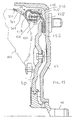
- a coupling device hydrokinetic 10 especially for vehicle transmission automobile, of the type comprising a sealed casing 12 filled with oil with two shells interconnected tightly at their periphery external.
- One of the shells, illustrated in the figures, has a wall called radial wall 14 which extends generally transversely in a plane perpendicular to the general axis X-X of rotation and symmetry axial of the coupling device 10.
- the radial wall 14 is made integrally in one sheet metal part of constant thickness and stamped and it extends, beyond its outer radial edge, by an annular portion axial orientation 16 in the form of a cylindrical skirt whose edge front end 18 is designed to allow the connection of this shell 12 with the other casing shell (not shown in the figures) which is shaped to form the impeller.
- the radial wall 14 includes a sleeve central 20.
- the rotational connection of the radial wall 14 to a shaft leading (not shown in the figure), here the crankshaft of the vehicle, is produced here using a flexible flange (not shown) attaching to threaded fasteners 300 integral with the wall 14.
- the sleeve extends axially rearward from a central portion 22 of the radial wall 14 which is axially offset forward with respect to the median radial plane in which the wall 14.
- the rear annular free end edge 24 of the sleeve 20 is welded to the smaller diameter rear portion 26 of a stepped ring thrust 28 which extends axially towards the rear, outside the casing 12, by a rear end cylindrical section 30 forming centering.
- the ring 28 is therefore secured to the wall 14.
- the front portion 32 of larger diameter of the ring thrust 28 extends axially inside the casing 12 and radially partly opposite the front internal face 34 of the central portion 22 of wall 14.
- the front part 32 of the push ring 28 defines externally a cylindrical annular surface 36 of axial orientation which constitutes an external peripheral guidance surface in axial sliding, here sealed, of an inner radial ferrule 38 belonging to a piston 40.
- the bearing surface 36 has a radial groove 42 which is designed to receive a seal (not shown).
- the part of large diameter 32 of the push ring 28 has a series pins 46, of axial orientation, which are angularly distributed by regular and which determine, with the face 34 of the part central 22 of the radial wall 14, as many orientation passages radial which connect an interior chamber 48, axially delimited by the wall 14 and the piston 40, with one or more channels 50 which pass through the smaller front cylindrical part diameter 26 of the thrust ring 28, to communicate the chamber 48 with the interior of the thrust ring 28 which is closed axially forward by the cylindrical section 30 and which opens out axially backwards inside the sleeve-shaped body 52 hollow cylindrical belonging to a hub 54 which is grooved internally 56 to allow its connection in rotation with a shaft led (not shown in the figures).
- the push ring 28 therefore has a central bore blind for supplying fluid to the chamber 48 via the channels 50, the lugs 46 and the driven shaft provided in a known manner with a channel Power.
- the hub 54 is coaxial with the other elements of the device 10, and in particular to the thrust ring 28, and it extends radially towards the outside, from the rear end portion 58 of its socket 52, by a flange 60 of radial orientation.
- a part 62 is attached to the flange 60, or alternatively on the thrust ring 28, to constitute an axial support piece, of a part, for the front radial face 64 of the front part 32 of the ring thrust 28 and, on the other hand, for the annular front end face 66 of the ferrule 38 for sliding guide of the piston 40.
- the part 62 therefore avoids metal-to-metal contacts and has a low coefficient of friction.
- the part 62 is essentially constituted by a plate in the form of a flat ring, forming a stop plate.
- the rear flat annular face 74 of the plate 62 constitutes a bearing face for the ferrule 38 and for the front radial face 64 of the ring 28 which has a countersink for centering it on the edge inner cylindrical of the plate 62.
- the insert 62 therefore also ensures centering of the ring 28 relative to the hub 54.
- the plate 62 also forms a spacer between the flange 60 and the piston 40, that is to say that, in the disassembled position of the piston 40, there is an axial clearance between the front annular face 80 vis-à-vis the part inner radial 82 of the piston 40 and the annular face opposite 84 of the flange 60.
- the main central part of the flange 60 extends radially outward by an outer radial edge 86, which has an annular countersink 88 formed in the front radial face 90 of the flange 60.
- the flange 60 is therefore thinner at the edge 86.
- the radial bottom of the countersink 88 constitutes an axial bearing surface backwards for a flat annular inner radial orientation radial 92 belonging to a veil 94.
- This inner radial edge 92 is fixed to the edge 86 of the flange 60 by a series of rivets 95 each of which passes through a hole 96 formed in the edge 86 of the flange 60 and a corresponding hole 98 formed in the edge internal radial 92 of the web 94.
- Each rivet 95 also passes through a hole 100 formed in an internal ring 102 belonging to a wheel turbine 104.
- the ring 102 extends radially inwards in a plane radial and is adjacent to the front annular face 106 of the edge 92 of the web 94 so as to also be received inside the counterbore 88.
- the flange 94 From its inner radial edge 92, the flange 94 comprises, radially outwards, a bend 108 then a central portion 110 in the form of a flat ring so as to conform substantially to the outline facing the turbine wheel 104, then a portion 112 of shape general frustoconical, and an outer peripheral annular portion 114 generally in the form of a half torus. This portion 114 extends in mostly radially above the piston 40 and is located at the outer periphery of the turbine wheel 104 with blades.
- the annular portion 114 of concave shape is shaped generally in an axially oriented groove which is open axially backwards towards the radial wall 14 and is very close to the piston 40 extending to the outer periphery of the apparatus 10 and the turbine wheel 104.
- said portion comprises a outer annular portion 116 of axial orientation which extends axially backwards from a front part 118 of shape concave, here of generally semi-circular section, which extends in a radial plane and which is connected to the outer peripheral edge of the portion frustoconical 112 by an inner annular part 120 of orientation globally axial.
- the front part 118 is flat in shape at level of its connection area to the interior part 120 to come very close to the turbine wheel 104, here tangentially, and occupy all available space at the outer periphery of the turbine wheel 104.
- the peripheral annular portion 114 has a C profile, and it receives elastic action organs circumferential, here in the form of a series of coil springs 122 with circumferential action, which operate on the same circumference and whose outside diameter is slightly less than the height vertical of the groove 114 between its parts 116,120.
- the springs 122 are thus guided circumferentially.
- the outer part 116 is axially longer that the internal part 120 slightly inclined in the direction of the axis X-X of symmetry for the introduction of the springs 122 into the groove 114. This internal part 120 facilitates the release of the springs 122.
- the annular portion 114 comprises zones which are circumferential bearing surfaces formed by the circumferential ends of stamped 124 and 126 opposite which are formed radially inward, respectively outward, in the outer 116 and inner 120 annular parts.
- the disc 152 is a part in the general shape of a flat ring. This disk 152 is disengageably connected to wall 14.
- the rear friction lining 160 of the friction disc 152 is provided to cooperate with an annular friction track 170 which is formed vis-à-vis in the inner face of the radial wall 14.
- the friction track 170 is machined in the inner face of a middle portion 172 of the radial wall 14 which is produced, by means of an annular axial stamping, so as to extend in a vertical plane offset axially forward, that is to say to the left when considering figure 1, in relation to the vertical median plane in which the radial wall 14 extends.
- the front friction lining 162 is designed to cooperate with an annular friction track 176, oriented axially towards the back, which is formed on the corresponding face of the part outer annular device 178 of the piston 40.
- the disc 152 is devoid of linings 160, 162 and rubs directly on the tracks 170,176.
- this peripheral part external radial 178 of the piston 40 is offset axially towards the rear relative to the general radial plane in which the piston 40 extends.
- the piston 40 is linked in rotation to the radial wall 14 by a series elastic tabs 180 arranged substantially in a circumference and which intervene tangentially between the cover12 and the piston 14 while allowing relative axial displacement of these two elements as described in document FR97 15600 of 8 December 1997.
- the friction disc 152 has at its outer periphery drive legs 128 which extend axially forward towards the annular portion 114, substantially halfway between the annular parts 116 and 120.
- the drive legs 128 are distributed angularly from in a regular way and each of them is connected to the peripheral edge outside 153 of the friction disc 152 by a connection elbow 130 at right angles.
- Each drive leg 128 comprises, in the vicinity of its front axial end 132, two opposite fingers or studs 134.
- Each stud 134 is a centering and holding stud of a spring 122 which extends circumferentially from a side edge 136 and which penetrates inside the open end 138 of the adjacent spring.
- Plots 134 here have a trapezoidal shape.
- Circumferential leg spacing 128 and the length of each spring 122 are such that each spring is mounted between two studs or fingers 134 opposite between which it is held to form a structural whole with the friction disc 152 before mounting the latter, beforehand fitted with its springs 122, in the device 10.
- the springs are held axially towards the rear by retaining lugs 140 which extend radially outward from from the peripheral edge 153 of the friction disc 152 while being slightly folded axially forward to come into contact with the part upper of the springs 122 radially above the legs 128 and here radially below the stamped 124.
- each spring 122 in position mounted between two studs 134, is slightly less than the distance separating the facing and consecutive bearing surfaces 124, 126 of so that the sub-assembly constituted by the friction disc 152 which carries the springs 122 can be inserted axially, from rear to front in the annular portion 114 in the form of a groove.
- the legs 140 for retaining the springs 122 are bent in S so as to extend overall from tilted forward towards the annular portion 114.
- the device 10 has no circumferential damping springs intervening between the friction disc 152 and the web.
- a friction disc 152 is used in all points identical to that described with reference to Figures 1 and 2 which is rotated by a veil whose peripheral annular portion is modified for, beyond from the peripheral edge 113 of the frustoconical part 112, extend by lugs 148 which extend generally radially towards the outside being inclined axially backwards.
- the legs of reaction 148 are evenly distributed angularly by sets of three, two legs 140 being received practically without play circumferential between three consecutive 148 reaction legs.
- the turbine wheel 104 is driven by an impeller (not shown), thanks to the circulation of fluid contained in the casing between the blades of said wheels and that, after starting the vehicle, the locking clutch allows, to avoid sliding phenomena between the wheels turbine and impeller, a connection of the driven shaft connected to the wheel turbine, with the drive shaft connected to the radial wall 14 of the housing.
- the locking clutch thus intervenes between the wheel turbine and the radial wall. It slides by its piston 40 on the ring of thrust 28 integral with the radial wall 14.
- the tightening control or clutch engagement and release is ensured, according to a known technique, by varying the pressure in chamber 48 axially delimited by the piston 40 and the radial wall 14 and radially inwards by the thrust ring 28 and towards the exterior by the friction disc 152.
- the wall 14 forms the actual input element of the device hydrokinetic coupling 10 because it is connected to the driving shaft, while the turbine wheel 104, via the hub 54 integral with the latter, forms the outlet element of said device 10.
- the piston 40 can be linked in rotation to the radial wall 14 using a ring integral with the piston and having axial grooves, forming mortises, in which engage radial lugs, forming tenons, belonging to a plate integral with the wall 14 and forming a friction track for the rear friction lining.
- the plate has axial legs each engaged between two stampings formed in the piston.
- the friction linings 160, 162 can be secured, for example example by bonding respectively part 178 of piston 40 and the middle part 172 of the radial wall 114.
- the disc 152 is a friction disc intended to be tightened so disengageable between the wall 14, optionally provided with a coating, and the piston 40, possibly provided with a coating.
- the friction linings 160,162 can be fitted with grooves as described in document WO-A-93 13339 cited above. These grooves allow a controlled sliding of the linings 160,162.
- the friction disc 152 is interposed between the two friction linings 160,162 possibly in one piece with the friction disc 152.
- fingers or studs 134 can be used for mounting support cups 234 interposed between the ends circumferential springs 122 and legs 128, as shown in figure 7.
- the cups 234 protect the legs 128.
- the cups 234 have a protuberance centrally cylindrical 235, here in the form of hollow pawns, penetrating inside a spring 122 to serve as a support by its end face 236 for a spring with coil 222 surrounded by spring 122.
- the springs 122,222 are mounted concentrically and the cup 234 bears against the lateral edge 136 of the tab 128 while being maintained by the central stud 134 entering the protuberance 235, of circumferential orientation, of the cup 234 for maintenance of it.
- the cup 234 is therefore hat-shaped and serves as spring centralizer 122 and internal spring support 222.
- the engine torque is transmitted from the wall 14 to the turbine wheel via a torsion damper with two transmission parts torque, namely the friction disc and the wall 94 with a single part of the peripheral annular portion for guiding the organs elastic 122,222 intervening between these two parts.
- the inner part 120 of the portion 114 can come closer piston 40, the outer periphery of which is chamfered so as not to interfere with the connection area of part 120 with the portion tapered 122 of the veil.
- the elastic members 122 carried by the friction disc 152, extend above the outer periphery of the piston 40.
- the legs 128 symmetrically attack the springs, that is to say diametrically.
- legs 128 can be axially inclined as well as the upper part 116.
- the annular portion 114 can be fixed directly to the turbine wheel 104, for example by stapling, stapling, friction welding or using a weld bead. Such a codon is visible at 200 in FIG. 8. In in this case the welding is carried out between the turbine wheel 104 and the part flat 218 connecting the front part 118, of curved shape. Of course we can keep the outer part of the veil 94 and fix the central portion 110 directly on the turbine wheel 104 by stapling or welding as visible in 201 in FIG. 8.
- This second fixing point 201 reinforces the direct fixing of the portion 114.
- the interior part 120 of the portion 114 is interrupted by fixing lugs 220 directed radially inward and conforming to the shape of the turbine wheel.
- fixing lugs 220 directed radially inward and conforming to the shape of the turbine wheel.
- a staple tab of a blade of the turbine wheel at torus outside of it The tab 301 passes through an opening 302 made in the fixing lugs 220 to then be folded down contact of this tab 220 so that each fixing tab 220 is stapled to the turbine wheel 104.
- the fixing lugs 220 are advantageously cut in the area of the internal part 120 between two supports 126 using the central part of the material which is lost during the production of the portion 114.
- the fixing lugs 320 are cut out in the internal part 120 between two supports 126 and in the bottom 118 constituting the front part of the portion 114. These legs 320 are directed radially outwards to be stapled in contact with the wheel 104 as in FIG. 11.
- the stapling tabs can be from the annular portion for each pass through an opening in the outer toroid of the turbine wheel to be folded inwardly in contact with said torus.
- the stapling tabs 401 come from the front part 118 between two supports 126 to pass through an opening 402 of the wheel 104 and be folded down in contact with the outer toroid 403 of the wheel 104.
- the stapling tabs can come from the vanes of the wheel 104 for stapling the part 118 contrary to the figure 13.
- axial support legs 317 and mounting lugs 318 axially inclined towards the X-X axis in the part interior 316 and this circumferentially alternately.
- the legs 318 by their inclination, facilitate the mounting of the springs 122.
- the front part 118 of the concave portion 114 comprises here an outer portion 116 of axial orientation which extends rearwardly from a front part 118 of annular concave shape extending in circular arc over 180 ° and connected to an interior 316 inclined towards the X-X axis and connecting to the web 94.
- the support zones 324, formed in the part 116 can be made by cutting and consist of strips of material.
- tongues 180 are fixed to the piston 40 by simple rivets as described in document FR97 15600 filed on 8 December 1997, plugs (not visible) being provided in the piston 40 for fixing the part to the support by riveting.
- the piston has plugs facing the fasteners to the wall 14 of the support plate 181 of the tongues, which are thus fixed in advance to the piston 40 which can be mounted in Figure 1 on the ring despite the presence of the springs 122 and the disc 152 since the springs 122 extend radially above the web 122.
- the stampings 124 are replaced by extra thicknesses from the external part 116.
- the external part 116 has at its level free end of the axes of axial orientation directed towards the wall 14, which we fold back afterwards to bring them into contact with the periphery internal of the external part 116.
- Stampings 124, 126 can be replaced by parts welded or attached in any way, for example by snap-fastening, respectively on the internal periphery of the part external 116 and on the external periphery of the internal part 120.
- stampings 124, 126 may belong to a same part added by welding inside the portion 114 as described in document FRA-2 709 164.
- This part can be attached by snapping onto the portion 114.
- FIG. 14 So in Figure 14 we see at 500 such a part overall U-shaped with a bottom in contact with the front part 118 and two branch parallel to the drive legs 128 and extending from one side and on the other with an associated leg 128.
- the branches serve to support the circumferential ends of the springs 122.
- the outer part 116 has at its free end beads 600 in the form of sectors annulars directed radially inwards and therefore towards the piston 40 which creates a safety stop limiting movement springs 122, in order to prevent them from escaping from the portion 114.
- the stop 600 allowing axial movement of the legs 128 and the springs 122.
- the part internal 120 has holes 602 in which notches are mounted not referenced each belonging to the free end of a loop 502 extending the lower branch of part 500. penetrate without their circumferential play in their associated hole 602 for blocking in rotation of the part 500.
- the part 500 is thus mounted by threading and snap-fastening or clipping inside the portion 114; the tab 501 retracting when the bead 600 passes to deploy then in contact with the bead 600, while the notch enters its hole 602.
- the external part 116 and the front part 118 can be drilled respectively at 603 and 604 for receiving respectively a notch 503, here in the form of sawtooth, and an inclined leg 604 obtained by cutting the bottom of the part 500, the tab 501 being replaced by a transverse tab 505 can be deleted.
- the branches of the room 500 extend circumferentially.
- the branches of the part 500 extend transversely so that you need two 500 pieces between two springs consecutive as shown in Figure 17 with lugs fixing 220 as in FIG. 11, the legs 301 folded down circumferentially in contact with the wheel 104 being better visible in this figure.
- the parts 500 are stapled to the portion 114 using stapling tabs 701 from the bottom of parts 500 and folded down circumferentially in contact with the front part 118 and notches 703, 704 from the ends of the branches of the U-shaped part 500.
- the notches 703, 704 are each engaged in a notch made in the free end respectively of the external part 116 and of the internal part 120.
- the bottom of the part 500 is engaged in a window 706 in part 118 to clear the most space centrally possible for 128 drive legs without increasing axial dimensions.
- part 500 can be fixed by welding on the portion 114 preferably at several points.
- the annular portion 114 is divided into several parts 111 reported by stapling using legs 220 as in Figures 16 and 11 Parts 1114 have section a U shape with ends folded back transversely to form a support for the circumferential ends of the springs 122.
- the parts 1114 therefore consist of parts made of form of pockets open axially in one direction.
- the alternatively parts 1114 are fixed directly to the wheel 104 at the level of their front part for example by welding as visible on the figure 20.
- the limitation of the relative angular displacement of the disc by compared to veil 94 can be achieved by engagement of a extension of at least some of the legs 128 in windows associated carried out in the front part 118 of the portion 114 as visible in dotted lines in figure 1.
- the extensions penetrate with clearances circumferential in their associated windows to cooperate, according to the direction of relative displacement, with one of the side edges of this window at the end of movement.
- the free end of the extensions is advantageously chamfered, as visible at 228 in FIG. 1, for avoid interference with the turbine wheel.
- the extension is also shifted inward to interfere with the leg 140 concerned so that the support 126 is stepped in diameter.
- the legs cooperate after catching up a game with 500 coins to limit movement.
- the drive legs 128 can be slightly inclined towards the skirt 16; their inclination being weaker than those of the retaining tabs 140.
- the tabs 128 are in all cases of axial orientation and are intended to be disengageably connected to the transverse wall 14, here by means of the friction disc 152 which can be without friction lining 160, 162.
- This disc 152 is intended, in the illustrated figures coming into contact with the scope 170 of the wall 14 and this opposite the external periphery of the piston.
- the drive legs are attached so individual or issue piston 40. In all cases, the legs are carried by an annular element of generally radial orientation clean to come into disengageable contact with the internal face 170 of the radial wall of the casing 12.
Landscapes
- Engineering & Computer Science (AREA)
- General Engineering & Computer Science (AREA)
- Mechanical Engineering (AREA)
- Mechanical Operated Clutches (AREA)
- Hydraulic Clutches, Magnetic Clutches, Fluid Clutches, And Fluid Joints (AREA)
- Braking Arrangements (AREA)
- Snaps, Bayonet Connections, Set Pins, And Snap Rings (AREA)
- Orthopedics, Nursing, And Contraception (AREA)
- Soil Working Implements (AREA)
- Accommodation For Nursing Or Treatment Tables (AREA)
Description
- un carter doté d'une paroi, globalement d'orientation radiale, propre à être liée en rotation à un arbre menant ;
- une roue de turbine solidaire en rotation d'un moyeu propre à être lié en rotation à un arbre mené ;
- un embrayage de verrouillage, intervenant entre la roue de turbine et la paroi radiale, qui comporte, agencés axialement d'avant en arrière entre la roue de turbine et la paroi radiale :
- une portion annulaire périphérique d'orientation globalement axiale, solidaire en rotation de la roue de turbine, qui guide circonférentiellement et retient axialement vers l'avant des organes élastiques à action circonférentielle, et qui comporte localement des zones d'appui pour les extrémités circonférentielles des organes élastiques ;
- un piston, d'orientation globalement radiale, mobile axialement et lié en rotation au carter ;
- la portion annulaire périphérique est conformée en une gorge ou rainure axiale ouverte axialement vers l'arrière pour un montage aisé des organes élastiques et pour un bon guidage axial des organes élastiques ;
- ladite gorge est délimitée radialement par une partie annulaire extérieure et une partie annulaire intérieure, d'orientation globalement axiale, qui sont reliées par une partie avant de forme concave, d'orientation globalement radiale, formant fond ;
- les zones d'appui pour les extrémités circonférentielles des organes élastiques sont formées dans lesdites parties annulaires extérieure et intérieure de la portion annulaire périphérique du voile en sorte que lesdites zones sont robustes et longues axialement ;
- les pattes d'entraínement d'orientation axiale sont reliées au bord périphérique extérieur du disque de friction par des coudes de raccordement sensiblement à angle droit et peuvent être inclinées axialement ;
- chaque patte d'entraínement comporte deux plots ou doigts opposés qui s'étendent circonférentiellement et dont chacun constitue un plot de centrage qui est reçu dans un logement complémentaire formé à l'extrémité circonférentielle d'un organe élastique adjacent pour attelage axial de l'organe élastique aux pattes d'entraínement ;
- le disque de friction comporte des pattes de retenue, axialement vers l'arrière, des organes élastiques qui s'étendent, globalement radialement vers l'extérieur à partir du bord périphérique extérieur du disque de friction, en regard des organes élastiques pour retenue axiale de ceux-ci à l'arrière ;
- les pattes de retenue sont réparties angulairement de manière régulière entre les pattes d'entraínement ;
- l'extrémité libre de chaque patte de retenue est reçue, avec jeu circonférentiel, à l'intérieur d'une encoche formée dans le bord arrière de la partie annulaire extérieure de la portion annulaire périphérique du voile, de manière à limiter le déplacement angulaire du disque de friction par rapport à la portion annulaire qui s'étend à la périphérie externe de l'appareil d'accouplement hydrocinétique. Le disque de friction porte sur chacune de ses faces des garnitures de friction ;
- chaque organe élastique est un ressort à boudin à action circonférentielle ;
- chaque plot de centrage est reçu à l'intérieur de l'extrémité d'un ressort adjacent.
- la figure 1 est une demi-vue en section axiale d'un premier mode de réalisation d'un appareil d'accouplement conforme aux enseignements de l'invention ;
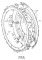
- la figure 2 est une vue en perspective qui illustre le voile et le disque de friction de l'appareil de la figure 1 ;
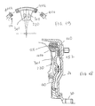
- les figures 3 et 4 sont des vues similaires à celles des figures 1 et 2 qui illustrent une variante de réalisation de l'appareil conforme aux enseignements de l'invention ;
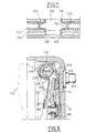
- les figures 5 et 6 sont des vues similaires à celles des figures 1 et 2 qui illustrent la possibilité d'utiliser le disque de friction illustré aux figures 1 à 4 en association avec un voile modifié dans un appareil d'accouplement ne comportant pas de ressorts à action circonférentielle;
- la figure 7 est une vue partielle de dessus montrant une patte d'entraínement équipée de coupelles d'appui pour montage de ressorts concentriques ;
- la figure 8 est une vue analogue à la figure 3 pour un autre exemple de réalisation ;
- la figure 9 est une demi-vue analogue à la figure 1 pour encore un autre exemple de réalisation ;
- la figure 10 est une vue partielle analogue à la figure 9 mais coupée en un autre endroit pour montrer un autre détail ;
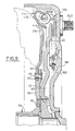
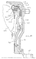
- les figures 11à 16 sont des vues analogues à la figure 1 pour encore d'autres exemples de réalisation ;
- la figure 17 est une vue de la portion de guidage selon la flèche 17 de la figure 16 ;
- les figures 18et 19 sont des vues analogues aux figures 16,17 pour encore un autre exemple de réalisation ;
- la figure 20 est une variante de la figure 18
Claims (15)
- Appareil (10) d'accouplement hydrocinétique, notamment pour véhicule automobile, du type comportant :un carter (12) doté d'une paroi (14), globalement d'orientation radiale, propre à être liée en rotation à un arbre menant ;une roue de turbine (104) solidaire en rotation d'un moyeu (54) propre à être lié en rotation à un arbre mené ;un embrayage de verrouillage, intervenant entre la roue de turbine (104) et la paroi radiale (14), qui comporte, agencés axialement d'avant en arrière entre la roue de turbine et la paroi radiale :une portion annulaire périphérique (114), d'orientation globalement axiale, solidaire en rotation de la roue de turbine (104), qui guide circonférentiellement et retient axialement vers l'avant des organes élastiques (122) à action circonférentielle, et qui comporte des zones (124, 126) d'appui pour les extrémités circonférentielles des organes élastiques (122), ladite portion (114) étant solidaire de la roue de turbine (104) en étant implantée à la périphérie externe de celle-ci et étant ouverte axialement vers l'arrière pour permettre l'introduction axiale, d'arrière en avant, des organes élastiques (122), entre les zones d'appui (124, 126);un piston (40), d'orientation globalement radiale, mobile axialement et lié en rotation au carter ;et un élément annulaire (152), d'orientation globalement radiale, d'une part, propre à venir en contact avec la face interne (170) de la paroi radiale (14) du carter (12) en vis à vis du piston et, d'autre part, qui comporte à sa périphérie extérieure des pattes d'entraínement (128) qui s'étendent globalement axialement vers l'arrière à l'intérieur de la portion annulaire périphérique (114) pour être reçues chacune entre les extrémités circonférentielles de deux organes élastiques consécutifs (122) à action circonférentielle, et qui est mobile axialement par rapport à la portion périphérique (114), caractérisé en ce que les organes élastiques (122) sont portés par l'élément annulaire (152) entre les pattes d'entraínement (128).
- Appareil selon la revendication précédente, caractérisé en ce que la portion annulaire périphérique (114) du voile est conformée en une gorge axiale ouverte axialement vers l'arrière.
- Appareil selon la revendication précédente, caractérisé en ce que ladite gorge (114) est délimitée radialement par une partie annulaire extérieure (116) et une partie annulaire intérieure (120,316), d'orientation globalement axiale, qui sont reliées par une partie avant (118) de forme concave, d'orientation globalement radiale, formant fond.
- Appareil selon la revendication précédente, caractérisé en ce que les zones d'appui (124, 126) pour les extrémités circonférentielles des organes élastiques (122) sont formées dans lesdites parties annulaires extérieure (116) et intérieure (120) de la portion annulaire périphérique (114).
- Appareil selon la revendication 3, caractérisé en ce que la partie annulaire intérieure (120,316) est inclinée en direction de l'axe de symétrie axiale (X-X-) que présente l'appareil.
- Appareil selon l'une quelconque des revendications précédentes, caractérisé en ce que les pattes d'entraínement (128) d'orientation axiale sont reliées au bord périphérique extérieur (153) de l'élément annulaire (152) par des coudes de raccordement (130) sensiblement à angle droit.
- Appareil selon la revendication 1, caractérisé en ce que chaque patte d'entraínement (128) comporte deux plots opposés (134) qui s'étendent circonférentiellement et dont chacun constitue un plot de centrage qui est reçu dans un logement complémentaire formé à l'extrémité circonférentielle (138) d'un organe élastique adjacent (122).
- Appareil selon la revendication 7, caractérisé en ce que des coupelles d'appui (234) sont interposées entre les extrémités circonférentielles des organes élastiques (122) et les pattes d'entraínement, les plots (134) étant reçus dans des protubérances (235) que présentent les coupelles.
- Appareil selon la revendication 3, caractérisé en ce que l'élément annulaire (152) comporte des pattes (140) de retenue, axialement vers l'arrière, des organes élastiques (122) qui s'étendent, globalement radialement vers l'extérieur à partir du bord périphérique extérieur (153) de l'élément annulaire, en regard des organes élastiques (122).
- Appareil selon la revendication précédente, caractérisé en ce que les pattes de retenue (140) sont réparties angulairement de manière régulière entre les pattes d'entraínement (128).
- Appareil selon la revendication 9, caractérisé en ce que l'extrémité libre (142) de chaque patte de retenue est reçue, avec jeu circonférentiel, à l'intérieur d'une encoche (144) formée dans le bord arrière (146) de la partie annulaire extérieure (116) de la portion annulaire périphérique (114) du voile (94), de manière à limiter le déplacement angulaire de l'élément annulaire (152) par rapport au voile.
- Appareil selon la revendication 7, caractérisé en ce que chaque organe élastique (122) est un ressort à boudin à action circonférentielle.
- Appareil selon la revendication précédente, caractérisé en ce que chaque plot de centrage (134) est reçu à l'intérieur de l'extrémité (138) d'un ressort adjacent.
- Appareil selon la revendication 1, caractérisé en ce que la portion annulaire périphérique (114) est solidaire d'un voile (94) qui comporte une partie périphérique intérieure en forme d'anneau plat (106) dont le bord radial intérieur (92) est reçu axialement entre la roue de turbine (104) et un flasque (86), d'orientation radiale, du moyeu (54), et en ce que le voile (94) est fixé au flasque (86) du moyeu (54).
- Appareil selon la revendication 1, caractérisé en ce que l'élément annulaire (152) consiste en un disque de friction propre à être serré entre la paroi radiale (14) et le piston (40).
Applications Claiming Priority (3)
| Application Number | Priority Date | Filing Date | Title |
|---|---|---|---|
| FR9802808A FR2775747B1 (fr) | 1998-03-03 | 1998-03-03 | Appareil d'accouplement hydrocinetique, notamment pour vehicule automobile |
| FR9802808 | 1998-03-03 | ||
| PCT/FR1999/000483 WO1999045294A1 (fr) | 1998-03-03 | 1999-03-03 | Appareil d'accouplement hydrocinetique, notamment pour vehicule automobile |
Publications (2)
| Publication Number | Publication Date |
|---|---|
| EP0980482A1 EP0980482A1 (fr) | 2000-02-23 |
| EP0980482B1 true EP0980482B1 (fr) | 2002-10-23 |
Family
ID=9523783
Family Applications (1)
| Application Number | Title | Priority Date | Filing Date |
|---|---|---|---|
| EP99937971A Expired - Lifetime EP0980482B1 (fr) | 1998-03-03 | 1999-03-03 | Appareil d'accouplement hydrocinetique, notamment pour vehicule automobile |
Country Status (10)
| Country | Link |
|---|---|
| EP (1) | EP0980482B1 (fr) |
| JP (1) | JP2001525046A (fr) |
| KR (1) | KR100600220B1 (fr) |
| BR (1) | BR9904843A (fr) |
| CA (1) | CA2288220C (fr) |
| CZ (1) | CZ293362B6 (fr) |
| DE (1) | DE19980568T1 (fr) |
| ES (1) | ES2186394T3 (fr) |
| FR (1) | FR2775747B1 (fr) |
| WO (1) | WO1999045294A1 (fr) |
Families Citing this family (15)
| Publication number | Priority date | Publication date | Assignee | Title |
|---|---|---|---|---|
| FR2768794A1 (fr) * | 1997-09-23 | 1999-03-26 | Valeo | Embrayage de verrouillage pour un appareil d'accouplement hydrocinetique, notamment de vehicule automobile |
| FR2783298B1 (fr) * | 1998-09-10 | 2001-02-09 | Valeo | Appareil d'accouplement hydrocinetique a rainure de refroidissement |
| FR2793295A1 (fr) | 1999-05-05 | 2000-11-10 | Valeo | Appareil d'accouplement hydrocinetique d'encombrement reduit, notamment pour vehicule automobile |
| FR2801084B1 (fr) * | 1999-11-17 | 2001-12-07 | Valeo | Appareil d'accouplement hydrocinetique, notamment pour vehicule automobile |
| FR2802265B1 (fr) * | 1999-12-10 | 2002-03-01 | Valeo | Embrayage de verrouillage, notamment pour vehicule automobile |
| FR2806457B1 (fr) * | 2000-03-17 | 2002-06-21 | Valeo | Dispositif d'accouplement hydrocinetique, en particulier pour vehicule automobile |
| FR2808066B1 (fr) * | 2000-04-21 | 2002-07-12 | Valeo | Appareil d'accouplement hydrocinetique, notamment pour vehicule automobile |
| FR2811048B1 (fr) * | 2000-06-29 | 2002-10-25 | Valeo | Appareil d'accouplement hydrocinetique, notamment pour vehicule automobile, comportant une butee a aiguilles entre le piston et le moyeu de turbine |
| FR2813651B1 (fr) * | 2000-09-05 | 2004-06-11 | Valeo | Appareil d'accouplement hydrocinetique, notamment pour vehicule automobile |
| AU2002210545A1 (en) | 2000-11-29 | 2002-06-11 | Thyssen Krupp Automotive Ag | Hydrodynamic torque converter |
| DE102008057658A1 (de) * | 2007-11-29 | 2009-06-04 | Luk Lamellen Und Kupplungsbau Beteiligungs Kg | Drehmomentwandler mit Verbindungsscheibe für eine Scheibenkupplung und mit Bogenfeder |
| US9322463B2 (en) * | 2014-04-25 | 2016-04-26 | Valeo Embrayages | Hydrokinetic torque coupling device with centered lock-up clutch friction disc, and method for assembling the same |
| US11174903B1 (en) * | 2019-05-28 | 2021-11-16 | Logan Clutch Corporation | Clutch assembly and system |
| US11525493B2 (en) * | 2019-12-19 | 2022-12-13 | Schaeffler Technologies AG & Co. KG | Torsional vibration damper with centered flanges |
| KR102446911B1 (ko) * | 2020-12-14 | 2022-09-22 | 주식회사 카펙발레오 | 토크 컨버터 |
Family Cites Families (6)
| Publication number | Priority date | Publication date | Assignee | Title |
|---|---|---|---|---|
| US4413711A (en) * | 1981-03-30 | 1983-11-08 | Borg-Warner Corporation | Extended travel damper in a lock-up clutch for a torque converter |
| US4790792A (en) * | 1983-12-22 | 1988-12-13 | Eaton Corporation | Torsion damping assembly |
| JPH07502325A (ja) * | 1991-12-23 | 1995-03-09 | フオード モーター カンパニー | 流体トルクコンバータ用のダンパ及びバイパスクラッチ |
| DE4397755A5 (de) * | 1992-10-12 | 2013-07-11 | Schaeffler Technologies AG & Co. KG | Kraftübertragungseinrichtung |
| DE4433256A1 (de) * | 1993-10-29 | 1995-05-04 | Luk Lamellen & Kupplungsbau | Drehmomentwandler |
| JP4341992B2 (ja) * | 1997-06-30 | 2009-10-14 | ヴァレオ | 自動車用ロックアップクラッチを有する流体動力カプリング装置 |
-
1998
- 1998-03-03 FR FR9802808A patent/FR2775747B1/fr not_active Expired - Fee Related
-
1999
- 1999-03-03 CA CA002288220A patent/CA2288220C/fr not_active Expired - Fee Related
- 1999-03-03 WO PCT/FR1999/000483 patent/WO1999045294A1/fr not_active Ceased
- 1999-03-03 CZ CZ19993908A patent/CZ293362B6/cs not_active IP Right Cessation
- 1999-03-03 KR KR1019997010067A patent/KR100600220B1/ko not_active Expired - Lifetime
- 1999-03-03 EP EP99937971A patent/EP0980482B1/fr not_active Expired - Lifetime
- 1999-03-03 BR BR9904843-4A patent/BR9904843A/pt not_active IP Right Cessation
- 1999-03-03 DE DE19980568T patent/DE19980568T1/de not_active Withdrawn
- 1999-03-03 JP JP54433999A patent/JP2001525046A/ja not_active Ceased
- 1999-03-03 ES ES99937971T patent/ES2186394T3/es not_active Expired - Lifetime
Also Published As
| Publication number | Publication date |
|---|---|
| ES2186394T3 (es) | 2003-05-01 |
| DE19980568T1 (de) | 2000-07-27 |
| CZ293362B6 (cs) | 2004-04-14 |
| WO1999045294A1 (fr) | 1999-09-10 |
| CZ9903908A3 (cs) | 2001-11-14 |
| JP2001525046A (ja) | 2001-12-04 |
| CA2288220C (fr) | 2008-08-19 |
| FR2775747B1 (fr) | 2000-07-13 |
| KR100600220B1 (ko) | 2006-07-13 |
| KR20010020436A (ko) | 2001-03-15 |
| FR2775747A1 (fr) | 1999-09-10 |
| CA2288220A1 (fr) | 1999-09-10 |
| EP0980482A1 (fr) | 2000-02-23 |
| BR9904843A (pt) | 2000-07-18 |
Similar Documents
| Publication | Publication Date | Title |
|---|---|---|
| EP0612384B1 (fr) | Amortisseur de torsion pour embrayage de verrouillage et embrayage de verrouillage comportant un tel amortisseur de torsion | |
| WO2000003158A1 (fr) | Appareil d'accouplement hydrocinetique, notamment pour vehicule automobile | |
| CA2288220C (fr) | Appareil d'accouplement hydrocinetique, notamment pour vehicule automobile | |
| FR2738890A1 (fr) | Amortisseur de torsion pour embrayage de verrouillage et embrayage de verrouillage comportant un tel amortisseur de torsion | |
| FR2721084A1 (fr) | Embrayage de verrouillage, notamment pour véhicules automobiles. | |
| WO1996035890A1 (fr) | Appareil d'accouplement hydrocinetique, notamment pour vehicule automobile | |
| WO2001007801A1 (fr) | Appareil d'accouplement hydrocinetique, notamment pour vehicule automobile | |
| WO1999001683A1 (fr) | Appareil d'accouplement hydrocinetique a embrayage de verrouillage, pour vehicule automobile | |
| WO1997042432A1 (fr) | Appareil d'accouplement hydrocinetique a piece d'entrainement de languettes, notamment pour vehicule automobile | |
| FR2760057A1 (fr) | Dispositif de roue libre a flasque de retenue et procede de mise en place du flasque | |
| WO2001036845A1 (fr) | Appareil d'accouplement hydrocinetique, notamment pour vehicule | |
| FR2695975A1 (fr) | Embrayage de verrouillage pour appareil d'acouplement hydrocinétique. | |
| WO2001007799A1 (fr) | Appareil d'accouplement hydrocinetique, notamment pour vehicule automobile | |
| EP1110012B1 (fr) | Appareil d'accouplement hydrocinetique d'encombrement reduit, notamment pour vehicule automobile | |
| FR2808066A1 (fr) | Appareil d'accouplement hydrocinetique, notamment pour vehicule automobile | |
| WO1997047901A1 (fr) | Appareil d'accouplement hydrocinetique, notamment pour vehicule automobile | |
| FR2825770A1 (fr) | Appareil d'accouplement hydrocinetique, notamment pour vehicule automobile | |
| FR2766894A1 (fr) | Appareil d'accouplement hydrocinetique a piece d'entrainement de languettes, notamment pour vehicule automobile | |
| EP1331126B1 (fr) | Système de propulsion hybride d'un véhicule automobile avec dispositif d'accouplement élastique entre le rotor de la machine électrique tournante réversible et l'arbre primaire de la boîte de vitesses du moteur thermique du véhicule automobile | |
| EP0836685B1 (fr) | Montage de butee de debrayage | |
| FR2788575A1 (fr) | Appareil d'accouplement hydrocinetique, notamment pour vehicule automobile | |
| FR2749634A1 (fr) | Amortisseur de torsion pour embrayage de verrouillage, notamment de vehicule automobile | |
| WO1998058194A1 (fr) | Procede de montage d'un embrayage de verrouillage pour un appareil d'accouplement hydrocinetique, notamment de vehicule automobile | |
| FR2747441A1 (fr) | Montage de butee de debrayage | |
| FR2797015A1 (fr) | Appareil d'accouplement hydrocinetique |
Legal Events
| Date | Code | Title | Description |
|---|---|---|---|
| PUAI | Public reference made under article 153(3) epc to a published international application that has entered the european phase |
Free format text: ORIGINAL CODE: 0009012 |
|
| 17P | Request for examination filed |
Effective date: 19991203 |
|
| AK | Designated contracting states |
Kind code of ref document: A1 Designated state(s): ES FR GB IT |
|
| GRAG | Despatch of communication of intention to grant |
Free format text: ORIGINAL CODE: EPIDOS AGRA |
|
| 17Q | First examination report despatched |
Effective date: 20020115 |
|
| GRAG | Despatch of communication of intention to grant |
Free format text: ORIGINAL CODE: EPIDOS AGRA |
|
| GRAH | Despatch of communication of intention to grant a patent |
Free format text: ORIGINAL CODE: EPIDOS IGRA |
|
| GRAH | Despatch of communication of intention to grant a patent |
Free format text: ORIGINAL CODE: EPIDOS IGRA |
|
| GRAA | (expected) grant |
Free format text: ORIGINAL CODE: 0009210 |
|
| RAP1 | Party data changed (applicant data changed or rights of an application transferred) |
Owner name: VALE EMBRAYAGES |
|
| AK | Designated contracting states |
Kind code of ref document: B1 Designated state(s): ES FR GB IT |
|
| REG | Reference to a national code |
Ref country code: GB Ref legal event code: FG4D Free format text: NOT ENGLISH |
|
| GBT | Gb: translation of ep patent filed (gb section 77(6)(a)/1977) |
Effective date: 20030217 |
|
| REG | Reference to a national code |
Ref country code: FR Ref legal event code: TP |
|
| REG | Reference to a national code |
Ref country code: ES Ref legal event code: FG2A Ref document number: 2186394 Country of ref document: ES Kind code of ref document: T3 |
|
| PLBE | No opposition filed within time limit |
Free format text: ORIGINAL CODE: 0009261 |
|
| STAA | Information on the status of an ep patent application or granted ep patent |
Free format text: STATUS: NO OPPOSITION FILED WITHIN TIME LIMIT |
|
| 26N | No opposition filed |
Effective date: 20030724 |
|
| PGFP | Annual fee paid to national office [announced via postgrant information from national office to epo] |
Ref country code: IT Payment date: 20080329 Year of fee payment: 10 |
|
| PG25 | Lapsed in a contracting state [announced via postgrant information from national office to epo] |
Ref country code: IT Free format text: LAPSE BECAUSE OF NON-PAYMENT OF DUE FEES Effective date: 20090303 |
|
| REG | Reference to a national code |
Ref country code: FR Ref legal event code: PLFP Year of fee payment: 18 |
|
| REG | Reference to a national code |
Ref country code: FR Ref legal event code: PLFP Year of fee payment: 19 |
|
| PGFP | Annual fee paid to national office [announced via postgrant information from national office to epo] |
Ref country code: FR Payment date: 20170331 Year of fee payment: 19 |
|
| PGFP | Annual fee paid to national office [announced via postgrant information from national office to epo] |
Ref country code: GB Payment date: 20170323 Year of fee payment: 19 |
|
| PGFP | Annual fee paid to national office [announced via postgrant information from national office to epo] |
Ref country code: ES Payment date: 20170331 Year of fee payment: 19 |
|
| GBPC | Gb: european patent ceased through non-payment of renewal fee |
Effective date: 20180303 |
|
| PG25 | Lapsed in a contracting state [announced via postgrant information from national office to epo] |
Ref country code: GB Free format text: LAPSE BECAUSE OF NON-PAYMENT OF DUE FEES Effective date: 20180303 |
|
| PG25 | Lapsed in a contracting state [announced via postgrant information from national office to epo] |
Ref country code: FR Free format text: LAPSE BECAUSE OF NON-PAYMENT OF DUE FEES Effective date: 20180331 |
|
| REG | Reference to a national code |
Ref country code: ES Ref legal event code: FD2A Effective date: 20190904 |
|
| PG25 | Lapsed in a contracting state [announced via postgrant information from national office to epo] |
Ref country code: ES Free format text: LAPSE BECAUSE OF NON-PAYMENT OF DUE FEES Effective date: 20180304 |