EP0980085B1 - Leitungsschutzschalter mit lichtbogenbetätigter Blasspule - Google Patents
Leitungsschutzschalter mit lichtbogenbetätigter Blasspule Download PDFInfo
- Publication number
- EP0980085B1 EP0980085B1 EP99115328A EP99115328A EP0980085B1 EP 0980085 B1 EP0980085 B1 EP 0980085B1 EP 99115328 A EP99115328 A EP 99115328A EP 99115328 A EP99115328 A EP 99115328A EP 0980085 B1 EP0980085 B1 EP 0980085B1
- Authority
- EP
- European Patent Office
- Prior art keywords
- arc
- circuit breaker
- coil
- contact
- contact element
- Prior art date
- Legal status (The legal status is an assumption and is not a legal conclusion. Google has not performed a legal analysis and makes no representation as to the accuracy of the status listed.)
- Expired - Lifetime
Links
- 238000000926 separation method Methods 0.000 claims abstract description 5
- 230000008878 coupling Effects 0.000 claims abstract description 3
- 238000010168 coupling process Methods 0.000 claims abstract description 3
- 238000005859 coupling reaction Methods 0.000 claims abstract description 3
- 238000010891 electric arc Methods 0.000 claims description 6
- 238000007664 blowing Methods 0.000 abstract description 11
- 238000010438 heat treatment Methods 0.000 description 5
- 238000010791 quenching Methods 0.000 description 5
- 230000000171 quenching effect Effects 0.000 description 5
- 230000000694 effects Effects 0.000 description 4
- 230000008901 benefit Effects 0.000 description 3
- 239000004020 conductor Substances 0.000 description 3
- 230000003068 static effect Effects 0.000 description 3
- 238000004804 winding Methods 0.000 description 3
- 239000002800 charge carrier Substances 0.000 description 2
- 230000006378 damage Effects 0.000 description 2
- 238000000034 method Methods 0.000 description 2
- 230000008569 process Effects 0.000 description 2
- 230000009471 action Effects 0.000 description 1
- 238000004061 bleaching Methods 0.000 description 1
- 230000008859 change Effects 0.000 description 1
- 230000001419 dependent effect Effects 0.000 description 1
- 230000005611 electricity Effects 0.000 description 1
- 230000020169 heat generation Effects 0.000 description 1
- 230000006872 improvement Effects 0.000 description 1
- 230000007246 mechanism Effects 0.000 description 1
- 230000005012 migration Effects 0.000 description 1
- 238000013508 migration Methods 0.000 description 1
Images
Classifications
-
- H—ELECTRICITY
- H01—ELECTRIC ELEMENTS
- H01H—ELECTRIC SWITCHES; RELAYS; SELECTORS; EMERGENCY PROTECTIVE DEVICES
- H01H9/00—Details of switching devices, not covered by groups H01H1/00 - H01H7/00
- H01H9/30—Means for extinguishing or preventing arc between current-carrying parts
- H01H9/44—Means for extinguishing or preventing arc between current-carrying parts using blow-out magnet
- H01H9/443—Means for extinguishing or preventing arc between current-carrying parts using blow-out magnet using permanent magnets
-
- H—ELECTRICITY
- H01—ELECTRIC ELEMENTS
- H01H—ELECTRIC SWITCHES; RELAYS; SELECTORS; EMERGENCY PROTECTIVE DEVICES
- H01H9/00—Details of switching devices, not covered by groups H01H1/00 - H01H7/00
- H01H9/30—Means for extinguishing or preventing arc between current-carrying parts
- H01H9/46—Means for extinguishing or preventing arc between current-carrying parts using arcing horns
- H01H9/465—Shunt circuit closed by transferring the arc onto an auxiliary electrode
-
- H—ELECTRICITY
- H01—ELECTRIC ELEMENTS
- H01H—ELECTRIC SWITCHES; RELAYS; SELECTORS; EMERGENCY PROTECTIVE DEVICES
- H01H73/00—Protective overload circuit-breaking switches in which excess current opens the contacts by automatic release of mechanical energy stored by previous operation of a hand reset mechanism
- H01H73/02—Details
- H01H73/18—Means for extinguishing or suppressing arc
Definitions
- the invention relates to a circuit breaker or circuit breaker with a fixed contact and with a switchable for producing a switchable electrical connection of two leads against this moving contact and a blow coil for the magnetic blowing of a resulting in the separation of the contacts electric arc.
- a resulting in a turn-off operation of a circuit breaker (LS-switch) electrical arc is highly undesirable because such a one hand, even after opening the contact point maintains the flow of current and thus extends the switching time.
- the electrical flashover referred to as an arc
- releases a comparatively large amount of heat which in particular leads to a strong heating of the switch contacts at the point of application of the arc. This heating can lead to damage or destruction of the contacts. It is therefore necessary to extinguish the arc which inevitably occurs during a switch-off process as quickly as possible after it has arisen.
- an extinguishing device in particular an extinguishing chamber, is usually provided on the side of the switch contacts.
- the arc In order to drive the arc out of the contact region into the extinguishing device and thus accelerate the switch-off process, the arc is frequently exposed to a magnetic field acting transversely to the arc gap. With the correct orientation of the magnetic field, a force known as the Lorentz force is exerted on the arc consisting of moving charge carriers, accelerating it in the direction of the extinguishing device.
- a magnetic field forced migration of the arc is referred to as magnetic blowing.
- the circuit breaker disclosed therein comprises a fixed contact and a switchable for making a switchable electrical connection of two leads against this moving contact and a blow coil for magnetic blowing of a resulting in the separation of the contacts electric arc, the blow coil between such a supply line and a contact element for coupling the arc is connected, that after disconnection of the contacts, an electrical connection of the leads via the arc and the blow coil takes place.
- the invention has for its object to provide a circuit breaker with an independent of the Stromflußraum and particularly effective magnetic blowing of an electric arc.
- a blow coil is provided for the magnetic blowing of the arc, on the one hand to a supply line, in particular the moving contact associated feed line is connected.
- the blow coil is connected to a contact element, which is provided as a derivative for the arc.
- the contact element is designed such that after separation of the contacts, the arc acts on the contact element.
- the blow coil is switched such that the two leads are conductively connected via the arc and the blow coil.
- the contact element is at least laterally as the moving contact in its open position formed with respect to an arc gap surrounding fishing shoe.
- the invention is based on the consideration that a magnetic blowing in an all-current circuit breaker is particularly effective when the direction of the magnetic field always changes with the Stromflußraum within the arc. It uses the experience that such a flow-dependent magnetic field change is advantageously achieved by means of a blow coil. In this case, an improvement over a conventional blinding coil could be achieved if the blown coil operated only in an existing arc, i. E. flowed through by electricity would. At all other times, however, a flow of current through the puff coil should be prevented in order to prevent unnecessary power consumption and thus unwanted heat generation. As is known, the described effect is achieved when the puff is contacted by the arc.
- the arc acts as a kind of switch that only switches on the blower coil when the arc is present.
- the contact element in the form of a catching shoe, which surrounds the moving contact in the open position at least laterally with respect to the arc gap, the moving contact immersed in its open position in the catching shoe, wherein the arc from the moving contact on skip the fishing shoe and turn on the blower field in this way.
- the contact element is provided with a permanent magnet, which generates a magnetic field approximately perpendicular to the magnetic field and thus deflects the arc in the direction of the contact element. In this way, the skipping of the arc to the contact element is significantly accelerated.
- the LS switch in an expedient embodiment comprises two rails, which feed the arc from the region of the contacts of a quenching chamber.
- the area formed between the rails is referred to as the expansion area of the arc.
- an insulating wall is preferably arranged between the expansion region of the arc and the blow coil, which prevents a rollover of the arc to the blow coil.
- a first running rail connects electrically conductively to the contact element.
- the electrical connection of the first rail to the contact element favors the skipping of the arc from the contact element on the running rail.
- the first running rail is only brought up to an insulating distance to the contact element and connected via a line parallel to the blow coil line with the corresponding supply line. In this way, the blow coil is only turned on to drive the arc from the contact element on the rails.
- the current flow through the blower coil is interrupted as soon as the arc has jumped over the rails. Heating the blown coil by the electrical power converted into it is thus further reduced.
- the blower coil can be realized in a particularly space-saving way.
- the advantages achieved by the invention are in particular that a particularly effective magnetic blowing of an arc takes place by means of an arc-operated blow coil, since the blow coil only in case of need, i. when an arc occurs in operation.
- the direction of the Lorentz force only depends on the winding sense of the blow coil, but not on the current flow direction within the arc.
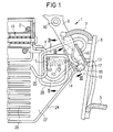
- FIG. 1 shows a partial view of a circuit breaker (LS switch) 1, which is arranged via two leads 2 and 3 in a circuit, not shown.
- the supply line 2 is electrically connected via a contact clip 4 with a fixed contact 5.
- the supply line 3 is electrically connected via conductors 6 and 7 to a contact arm 8, which carries a moving contact 9 end.
- the contact arm 8 is mounted pivotably about a rotation axis 10 such that in the closed position of the circuit breaker 1, not shown, the moving contact 9 rests on the fixed contact 5.
- the circuit is closed in this case via the supply line 2, the contact bracket 4, the fixed contact 5, the moving contact 9, the contact arm 8, the conductors 7 and 6 and the supply line 3.
- the LS-switch 1 is provided with a trigger shown only hinted 11, which emits a mechanical impulse to the contact arm 8 and a not-shown switching mechanism upon the occurrence of a predetermined trigger condition.
- a trigger condition for example, a short-circuit current can be set within the circuit.
- mechanical pulse of the contact arm 8 is pivoted in the open position shown in FIG 1.
- this pivoting of the contact arm 8 which can also be done manually in a conventional manner, the fixed contact 5 and the moving contact 9 are separated from each other.
- the moving contact 9 is arranged in its open position within a catching shoe 13.
- the trapping shoe 13 is formed substantially as a hollow cuboid of a conductive material.
- the catching shoe 13 is open at one of the fixed contact 5 facing side surface 14 and at one of the axis of rotation 10 of the contact arm 8 facing side surface 15, so that the interior 16 of the fishing boot 13 forms a pocket into which the contact arm 8 can be pivoted.
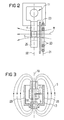
- the north-south axis 19 is at least approximately aligned with the axis of rotation 10 out.
- the north-south axis 19 thus runs approximately parallel to the contact arm 8 in its open position. In this way it is achieved that the static magnetic field S generated by the permanent magnet 18 (shown in FIG. 3) is approximately perpendicular to the arc gap 12.
- the fishing boot 13 is electrically connected to a blow coil 20, which in turn is electrically connected to the supply line 3.
- the blow coil 20 is wound in a coil plane 21 which is arranged parallel to a contact plane 22.
- the contact plane 22 is defined as the plane in which the contact arm 8 is pivotable, and which contains the contacts 5 and 9 and the arc gap 12.
- an insulating wall 23 is arranged between the inflation coil 20 and the contact plane 22. In this way it is prevented that the arc B rolls over the blow coil 20 and short circuits it.
- the LS switch 1 further comprises two rails 24 and 25, each near an end point of the arc gap 12 begin and extend from there to a quenching chamber 26. In this case, the distance between the rails 24,25 increases in their course to the quenching chamber 26 toward.
- the moving contact 9 associated with the first track 24 is electrically connected to the fishing boot 13.
- the second running rail 25 is formed from a remote from the trigger 11 and beyond the fixed contact 5 also extended part of the contact clip 4.
- the rails 24 and 25 thereby extend approximately within the contact plane 22.
- the area enclosed by the arc gap 12, the rails 24, 25 and the quenching chamber 26 is designated as the widening area 27 of the electric arc B.
- the magnetic field direction within the catching shoe 13 is approximately parallel to the north-south axis 19 of the permanent magnet 18.
- the arc B is displaced in the direction of a side wall 28 or 29 of the catching shoe 13 as a result of the Lorentz force F1.
- the direction of the Lorentz force F1 is - depending on the current flow direction within the arc B - either aligned with the side wall 28 or diametrically opposite to the opposite side wall 29.
- the arc B thus automatically switches on the bleaching coil 20, which now generates a magnetic field M which is approximately perpendicular to the contact plane 22. Under the influence of this magnetic field M, the arc B is acted upon by a further Lorentz force F2, which acts on the arc B in the direction of the rails 24,25. Under the action of the Lorentz force F2, the arc B jumps from the fixed contact 5 to the adjacent second running rail 25 or from the catching shoe 13 to the associated first running rail 24. Thereafter, the arc is fed along the extension region 27 to the quenching chamber 26, where the arc B is extinguished.
- the leads 2 and 3 are electrically isolated. Since in a reversal of the direction of current flow within the arc B, the direction of current flow inside the blow coil 20 and thus the direction of the magnetic field M reverses, the direction of the Lorentz force F2 depends only on the winding sense of the blow coil 20, but not from the current flow direction.
- the winding sense of the blow coil 20 is chosen such that the direction of the Lorentz force F2 is aligned with the expansion region 27 of the arc B.
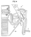
- FIG. 4 shows an advantageous development of the circuit breaker switch 1.
- the first running rail 24 is not connected directly to the catching shoe 13. Rather, an insulating gap 30 is formed between the running rail 24 and the fishing boot 13.
- the running rail 24 is connected by means of a separate line 31 to the supply line 3.
- This embodiment has the advantage that after skipping the arc B on the running rail 24, the puff 20 is de-energized. Another heating up the blow coil 20 and thus the LS switch 1 is thereby avoided.
Landscapes
- Arc-Extinguishing Devices That Are Switches (AREA)
- Circuit Breakers (AREA)
- Driving Mechanisms And Operating Circuits Of Arc-Extinguishing High-Tension Switches (AREA)
- Breakers (AREA)
Applications Claiming Priority (2)
| Application Number | Priority Date | Filing Date | Title |
|---|---|---|---|
| DE19836829 | 1998-08-13 | ||
| DE19836829 | 1998-08-13 |
Publications (3)
| Publication Number | Publication Date |
|---|---|
| EP0980085A2 EP0980085A2 (de) | 2000-02-16 |
| EP0980085A3 EP0980085A3 (de) | 2000-08-02 |
| EP0980085B1 true EP0980085B1 (de) | 2006-11-22 |
Family
ID=7877497
Family Applications (1)
| Application Number | Title | Priority Date | Filing Date |
|---|---|---|---|
| EP99115328A Expired - Lifetime EP0980085B1 (de) | 1998-08-13 | 1999-08-03 | Leitungsschutzschalter mit lichtbogenbetätigter Blasspule |
Country Status (4)
| Country | Link |
|---|---|
| EP (1) | EP0980085B1 (es) |
| AT (1) | ATE346366T1 (es) |
| DE (1) | DE59913992D1 (es) |
| ES (1) | ES2276490T3 (es) |
Cited By (3)
| Publication number | Priority date | Publication date | Assignee | Title |
|---|---|---|---|---|
| US7417520B2 (en) | 2006-08-01 | 2008-08-26 | Schaltbau Gmbh | Contactor for direct current and alternating current operation |
| DE102007054960B3 (de) * | 2007-11-17 | 2009-04-23 | Moeller Gmbh | Schaltgerät für Gleichstrom-Anwendungen |
| EP2061053A2 (de) | 2007-11-17 | 2009-05-20 | Moeller GmbH | Schaltgerät für Gleichstrom-Anwendungen |
Families Citing this family (6)
| Publication number | Priority date | Publication date | Assignee | Title |
|---|---|---|---|---|
| DE10352934B4 (de) * | 2003-11-11 | 2005-12-22 | Siemens Ag | Lichtbogen-Löschvorrichtung |
| EP2393096B1 (de) * | 2010-06-07 | 2013-02-13 | ABB Schweiz AG | Einfach unterbrechendes Niederspannungsschaltgerät, insbesondere Leitungsschutzschalter |
| DE102010031907B9 (de) * | 2010-07-22 | 2013-01-17 | Schaltbau Gmbh | Unidirektional schaltendes DC-Schütz |
| EP2642500A1 (de) * | 2012-03-21 | 2013-09-25 | Eaton Industries GmbH | DC-Schalter ohne Löschkammern |
| US10510506B1 (en) * | 2019-01-31 | 2019-12-17 | Carling Technologies, Inc. | Narrow profile circuit breaker with arc interruption |
| CN114937580B (zh) * | 2022-06-13 | 2025-11-14 | 浙江天正电气股份有限公司 | 一种用于直流断路器的灭弧室及直流断路器 |
Family Cites Families (5)
| Publication number | Priority date | Publication date | Assignee | Title |
|---|---|---|---|---|
| GB930101A (en) * | 1958-08-02 | 1963-07-03 | Whipp & Bourne Ltd | Improvements in or relating to air-break circuit-breakers |
| US3155801A (en) * | 1960-12-21 | 1964-11-03 | Ite Circuit Breaker Ltd | Arc chute side with encapsulated face wound blowout coil |
| DE2841004C2 (de) * | 1978-09-21 | 1980-10-02 | Licentia Gmbh | Leitungsschutzschalter mit zusätzlicher Blasschleife |
| DE3023673A1 (de) * | 1980-06-25 | 1982-01-14 | Deutsche Forschungs- und Versuchsanstalt für Luft- und Raumfahrt e.V., 5300 Bonn | Verfahren zur loeschung des abreissbogens in schaltern und magnetfeldanordnung im kathodenbereich eines schalters zur durchfuehrung dieses verfahrens |
| US4451718A (en) * | 1981-02-27 | 1984-05-29 | Mitsubishi Denki Kabushiki Kaisha | Circuit breaker |
-
1999
- 1999-08-03 EP EP99115328A patent/EP0980085B1/de not_active Expired - Lifetime
- 1999-08-03 DE DE59913992T patent/DE59913992D1/de not_active Expired - Lifetime
- 1999-08-03 ES ES99115328T patent/ES2276490T3/es not_active Expired - Lifetime
- 1999-08-03 AT AT99115328T patent/ATE346366T1/de not_active IP Right Cessation
Cited By (6)
| Publication number | Priority date | Publication date | Assignee | Title |
|---|---|---|---|---|
| US7417520B2 (en) | 2006-08-01 | 2008-08-26 | Schaltbau Gmbh | Contactor for direct current and alternating current operation |
| DE102007054960B3 (de) * | 2007-11-17 | 2009-04-23 | Moeller Gmbh | Schaltgerät für Gleichstrom-Anwendungen |
| EP2061053A2 (de) | 2007-11-17 | 2009-05-20 | Moeller GmbH | Schaltgerät für Gleichstrom-Anwendungen |
| EP2061052A2 (de) | 2007-11-17 | 2009-05-20 | Moeller GmbH | Schaltgerät für Gleichstrom-Anwendungen |
| DE102007054958A1 (de) | 2007-11-17 | 2009-06-04 | Moeller Gmbh | Schaltgerät für Gleichstrom-Anwendungen |
| EP2383761A1 (de) | 2007-11-17 | 2011-11-02 | Eaton Industries GmbH | Schaltgerät für Gleichstrom-Anwendungen |
Also Published As
| Publication number | Publication date |
|---|---|
| DE59913992D1 (de) | 2007-01-04 |
| ATE346366T1 (de) | 2006-12-15 |
| ES2276490T3 (es) | 2007-06-16 |
| EP0980085A3 (de) | 2000-08-02 |
| EP0980085A2 (de) | 2000-02-16 |
Similar Documents
| Publication | Publication Date | Title |
|---|---|---|
| DE102015000796B4 (de) | Schaltgerät mit permanentmagnetischer Lichtbogenlöschung | |
| EP3766090B1 (de) | Schutzschalter zur trennung eines stromkreises | |
| EP2079088A2 (de) | Schaltgerät, insbesondere Leistungsschaltgerät, mit zwei in Reihe geschalteten Schaltkontaktpaaren zur Unterbrechung einer Strombahn. | |
| EP2463878A1 (de) | Schalter mit Löschkammer | |
| DE102011089234B4 (de) | Lichtbogen-Löschvorrichtung und Schutzschaltgerät | |
| EP0980085B1 (de) | Leitungsschutzschalter mit lichtbogenbetätigter Blasspule | |
| DE10352934B4 (de) | Lichtbogen-Löschvorrichtung | |
| EP0039096B1 (de) | Blaskolbenschalter | |
| DE3141324A1 (de) | Leistungsschalter | |
| DE1640262A1 (de) | Stromunterbrecher | |
| DE29823717U1 (de) | Leitungsschutzschalter mit lichtbogenbetätigter Blasspule | |
| DE19524915A1 (de) | Lichtbogenlöschanordnung für einen elektrischen Schalter, insbesondere für einen Leitungsschutzschalter | |
| DE19629867C2 (de) | Strombegrenzender Leistungsschalter | |
| DE939460C (de) | Elektrischer Schalter | |
| EP3607572B1 (de) | Schaltgerät mit kontaktabdeckung | |
| EP0884747A2 (de) | Installationsschaltgerät | |
| EP2541574B1 (de) | Doppeltunterbrechendes Schutzschaltgerät | |
| EP0255008B1 (de) | Leitungsschutzschalter | |
| DE3803849C1 (en) | High-power switching path for protective switching devices | |
| EP3602593B1 (de) | Schaltgerät mit verbesserter permanentmagnetischer lichtbogenlöschung | |
| DE102009035299B4 (de) | Kontaktsystem und Schaltgerät | |
| DE102016213073A1 (de) | Schaltsystem | |
| EP0624889B1 (de) | Elektrischer Schalter | |
| EP1056105A2 (de) | Elektrisches Installationsgerät, insbesondere Leitungsschutzschalter | |
| DE102011080525A1 (de) | Doppeltunterbrechendes Schutzschaltgerät |
Legal Events
| Date | Code | Title | Description |
|---|---|---|---|
| PUAI | Public reference made under article 153(3) epc to a published international application that has entered the european phase |
Free format text: ORIGINAL CODE: 0009012 |
|
| AK | Designated contracting states |
Kind code of ref document: A2 Designated state(s): AT BE CH CY DE DK ES FI FR GB GR IE IT LI LU MC NL PT SE |
|
| AX | Request for extension of the european patent |
Free format text: AL;LT;LV;MK;RO;SI |
|
| PUAL | Search report despatched |
Free format text: ORIGINAL CODE: 0009013 |
|
| AK | Designated contracting states |
Kind code of ref document: A3 Designated state(s): AT BE CH CY DE DK ES FI FR GB GR IE IT LI LU MC NL PT SE |
|
| AX | Request for extension of the european patent |
Free format text: AL;LT;LV;MK;RO;SI |
|
| 17P | Request for examination filed |
Effective date: 20000818 |
|
| AKX | Designation fees paid |
Free format text: AT BE CH CY DE DK ES FI FR GB GR IE IT LI LU MC NL PT SE |
|
| GRAP | Despatch of communication of intention to grant a patent |
Free format text: ORIGINAL CODE: EPIDOSNIGR1 |
|
| GRAS | Grant fee paid |
Free format text: ORIGINAL CODE: EPIDOSNIGR3 |
|
| GRAA | (expected) grant |
Free format text: ORIGINAL CODE: 0009210 |
|
| AK | Designated contracting states |
Kind code of ref document: B1 Designated state(s): AT BE CH CY DE DK ES FI FR GB GR IE IT LI LU MC NL PT SE |
|
| PG25 | Lapsed in a contracting state [announced via postgrant information from national office to epo] |
Ref country code: NL Free format text: LAPSE BECAUSE OF FAILURE TO SUBMIT A TRANSLATION OF THE DESCRIPTION OR TO PAY THE FEE WITHIN THE PRESCRIBED TIME-LIMIT Effective date: 20061122 Ref country code: IE Free format text: LAPSE BECAUSE OF FAILURE TO SUBMIT A TRANSLATION OF THE DESCRIPTION OR TO PAY THE FEE WITHIN THE PRESCRIBED TIME-LIMIT Effective date: 20061122 Ref country code: FI Free format text: LAPSE BECAUSE OF FAILURE TO SUBMIT A TRANSLATION OF THE DESCRIPTION OR TO PAY THE FEE WITHIN THE PRESCRIBED TIME-LIMIT Effective date: 20061122 |
|
| REG | Reference to a national code |
Ref country code: GB Ref legal event code: FG4D Free format text: NOT ENGLISH |
|
| REG | Reference to a national code |
Ref country code: CH Ref legal event code: EP |
|
| GBT | Gb: translation of ep patent filed (gb section 77(6)(a)/1977) |
Effective date: 20061127 |
|
| REG | Reference to a national code |
Ref country code: IE Ref legal event code: FG4D Free format text: LANGUAGE OF EP DOCUMENT: GERMAN |
|
| REF | Corresponds to: |
Ref document number: 59913992 Country of ref document: DE Date of ref document: 20070104 Kind code of ref document: P |
|
| PG25 | Lapsed in a contracting state [announced via postgrant information from national office to epo] |
Ref country code: SE Free format text: LAPSE BECAUSE OF FAILURE TO SUBMIT A TRANSLATION OF THE DESCRIPTION OR TO PAY THE FEE WITHIN THE PRESCRIBED TIME-LIMIT Effective date: 20070222 Ref country code: DK Free format text: LAPSE BECAUSE OF FAILURE TO SUBMIT A TRANSLATION OF THE DESCRIPTION OR TO PAY THE FEE WITHIN THE PRESCRIBED TIME-LIMIT Effective date: 20070222 |
|
| PG25 | Lapsed in a contracting state [announced via postgrant information from national office to epo] |
Ref country code: PT Free format text: LAPSE BECAUSE OF FAILURE TO SUBMIT A TRANSLATION OF THE DESCRIPTION OR TO PAY THE FEE WITHIN THE PRESCRIBED TIME-LIMIT Effective date: 20070423 |
|
| NLV1 | Nl: lapsed or annulled due to failure to fulfill the requirements of art. 29p and 29m of the patents act | ||
| ET | Fr: translation filed | ||
| REG | Reference to a national code |
Ref country code: ES Ref legal event code: FG2A Ref document number: 2276490 Country of ref document: ES Kind code of ref document: T3 |
|
| REG | Reference to a national code |
Ref country code: IE Ref legal event code: FD4D |
|
| PLBE | No opposition filed within time limit |
Free format text: ORIGINAL CODE: 0009261 |
|
| STAA | Information on the status of an ep patent application or granted ep patent |
Free format text: STATUS: NO OPPOSITION FILED WITHIN TIME LIMIT |
|
| 26N | No opposition filed |
Effective date: 20070823 |
|
| BERE | Be: lapsed |
Owner name: SIEMENS A.G. Effective date: 20070831 |
|
| REG | Reference to a national code |
Ref country code: CH Ref legal event code: PL |
|
| PG25 | Lapsed in a contracting state [announced via postgrant information from national office to epo] |
Ref country code: MC Free format text: LAPSE BECAUSE OF NON-PAYMENT OF DUE FEES Effective date: 20070831 Ref country code: LI Free format text: LAPSE BECAUSE OF NON-PAYMENT OF DUE FEES Effective date: 20070831 Ref country code: GR Free format text: LAPSE BECAUSE OF FAILURE TO SUBMIT A TRANSLATION OF THE DESCRIPTION OR TO PAY THE FEE WITHIN THE PRESCRIBED TIME-LIMIT Effective date: 20070223 Ref country code: CH Free format text: LAPSE BECAUSE OF NON-PAYMENT OF DUE FEES Effective date: 20070831 |
|
| PG25 | Lapsed in a contracting state [announced via postgrant information from national office to epo] |
Ref country code: BE Free format text: LAPSE BECAUSE OF NON-PAYMENT OF DUE FEES Effective date: 20070831 |
|
| PG25 | Lapsed in a contracting state [announced via postgrant information from national office to epo] |
Ref country code: AT Free format text: LAPSE BECAUSE OF NON-PAYMENT OF DUE FEES Effective date: 20070803 |
|
| PG25 | Lapsed in a contracting state [announced via postgrant information from national office to epo] |
Ref country code: LU Free format text: LAPSE BECAUSE OF NON-PAYMENT OF DUE FEES Effective date: 20070803 Ref country code: CY Free format text: LAPSE BECAUSE OF FAILURE TO SUBMIT A TRANSLATION OF THE DESCRIPTION OR TO PAY THE FEE WITHIN THE PRESCRIBED TIME-LIMIT Effective date: 20061122 |
|
| PGFP | Annual fee paid to national office [announced via postgrant information from national office to epo] |
Ref country code: ES Payment date: 20090909 Year of fee payment: 11 |
|
| PGFP | Annual fee paid to national office [announced via postgrant information from national office to epo] |
Ref country code: GB Payment date: 20090813 Year of fee payment: 11 |
|
| PGFP | Annual fee paid to national office [announced via postgrant information from national office to epo] |
Ref country code: DE Payment date: 20101018 Year of fee payment: 12 |
|
| GBPC | Gb: european patent ceased through non-payment of renewal fee |
Effective date: 20100803 |
|
| PG25 | Lapsed in a contracting state [announced via postgrant information from national office to epo] |
Ref country code: GB Free format text: LAPSE BECAUSE OF NON-PAYMENT OF DUE FEES Effective date: 20100803 |
|
| REG | Reference to a national code |
Ref country code: ES Ref legal event code: FD2A Effective date: 20111020 |
|
| PG25 | Lapsed in a contracting state [announced via postgrant information from national office to epo] |
Ref country code: ES Free format text: LAPSE BECAUSE OF NON-PAYMENT OF DUE FEES Effective date: 20100804 |
|
| PGFP | Annual fee paid to national office [announced via postgrant information from national office to epo] |
Ref country code: FR Payment date: 20110826 Year of fee payment: 13 |
|
| PGFP | Annual fee paid to national office [announced via postgrant information from national office to epo] |
Ref country code: IT Payment date: 20110824 Year of fee payment: 13 |
|
| REG | Reference to a national code |
Ref country code: FR Ref legal event code: ST Effective date: 20130430 |
|
| PG25 | Lapsed in a contracting state [announced via postgrant information from national office to epo] |
Ref country code: IT Free format text: LAPSE BECAUSE OF NON-PAYMENT OF DUE FEES Effective date: 20120803 |
|
| PG25 | Lapsed in a contracting state [announced via postgrant information from national office to epo] |
Ref country code: DE Free format text: LAPSE BECAUSE OF NON-PAYMENT OF DUE FEES Effective date: 20130301 |
|
| PG25 | Lapsed in a contracting state [announced via postgrant information from national office to epo] |
Ref country code: FR Free format text: LAPSE BECAUSE OF NON-PAYMENT OF DUE FEES Effective date: 20120831 |
|
| REG | Reference to a national code |
Ref country code: DE Ref legal event code: R119 Ref document number: 59913992 Country of ref document: DE Effective date: 20130301 |