EP0980085B1 - Power circuit breaker with blast coil operated by the arc - Google Patents
Power circuit breaker with blast coil operated by the arc Download PDFInfo
- Publication number
- EP0980085B1 EP0980085B1 EP99115328A EP99115328A EP0980085B1 EP 0980085 B1 EP0980085 B1 EP 0980085B1 EP 99115328 A EP99115328 A EP 99115328A EP 99115328 A EP99115328 A EP 99115328A EP 0980085 B1 EP0980085 B1 EP 0980085B1
- Authority
- EP
- European Patent Office
- Prior art keywords
- arc
- circuit breaker
- coil
- contact
- contact element
- Prior art date
- Legal status (The legal status is an assumption and is not a legal conclusion. Google has not performed a legal analysis and makes no representation as to the accuracy of the status listed.)
- Expired - Lifetime
Links
Images
Classifications
-
- H—ELECTRICITY
- H01—ELECTRIC ELEMENTS
- H01H—ELECTRIC SWITCHES; RELAYS; SELECTORS; EMERGENCY PROTECTIVE DEVICES
- H01H9/00—Details of switching devices, not covered by groups H01H1/00 - H01H7/00
- H01H9/30—Means for extinguishing or preventing arc between current-carrying parts
- H01H9/44—Means for extinguishing or preventing arc between current-carrying parts using blow-out magnet
- H01H9/443—Means for extinguishing or preventing arc between current-carrying parts using blow-out magnet using permanent magnets
-
- H—ELECTRICITY
- H01—ELECTRIC ELEMENTS
- H01H—ELECTRIC SWITCHES; RELAYS; SELECTORS; EMERGENCY PROTECTIVE DEVICES
- H01H9/00—Details of switching devices, not covered by groups H01H1/00 - H01H7/00
- H01H9/30—Means for extinguishing or preventing arc between current-carrying parts
- H01H9/46—Means for extinguishing or preventing arc between current-carrying parts using arcing horns
- H01H9/465—Shunt circuit closed by transferring the arc onto an auxiliary electrode
-
- H—ELECTRICITY
- H01—ELECTRIC ELEMENTS
- H01H—ELECTRIC SWITCHES; RELAYS; SELECTORS; EMERGENCY PROTECTIVE DEVICES
- H01H73/00—Protective overload circuit-breaking switches in which excess current opens the contacts by automatic release of mechanical energy stored by previous operation of a hand reset mechanism
- H01H73/02—Details
- H01H73/18—Means for extinguishing or suppressing arc
Definitions
- the invention relates to a circuit breaker or circuit breaker with a fixed contact and with a switchable for producing a switchable electrical connection of two leads against this moving contact and a blow coil for the magnetic blowing of a resulting in the separation of the contacts electric arc.
- a resulting in a turn-off operation of a circuit breaker (LS-switch) electrical arc is highly undesirable because such a one hand, even after opening the contact point maintains the flow of current and thus extends the switching time.
- the electrical flashover referred to as an arc
- releases a comparatively large amount of heat which in particular leads to a strong heating of the switch contacts at the point of application of the arc. This heating can lead to damage or destruction of the contacts. It is therefore necessary to extinguish the arc which inevitably occurs during a switch-off process as quickly as possible after it has arisen.
- an extinguishing device in particular an extinguishing chamber, is usually provided on the side of the switch contacts.
- the arc In order to drive the arc out of the contact region into the extinguishing device and thus accelerate the switch-off process, the arc is frequently exposed to a magnetic field acting transversely to the arc gap. With the correct orientation of the magnetic field, a force known as the Lorentz force is exerted on the arc consisting of moving charge carriers, accelerating it in the direction of the extinguishing device.
- a magnetic field forced migration of the arc is referred to as magnetic blowing.
- the circuit breaker disclosed therein comprises a fixed contact and a switchable for making a switchable electrical connection of two leads against this moving contact and a blow coil for magnetic blowing of a resulting in the separation of the contacts electric arc, the blow coil between such a supply line and a contact element for coupling the arc is connected, that after disconnection of the contacts, an electrical connection of the leads via the arc and the blow coil takes place.
- the invention has for its object to provide a circuit breaker with an independent of the Stromflußraum and particularly effective magnetic blowing of an electric arc.
- a blow coil is provided for the magnetic blowing of the arc, on the one hand to a supply line, in particular the moving contact associated feed line is connected.
- the blow coil is connected to a contact element, which is provided as a derivative for the arc.
- the contact element is designed such that after separation of the contacts, the arc acts on the contact element.
- the blow coil is switched such that the two leads are conductively connected via the arc and the blow coil.
- the contact element is at least laterally as the moving contact in its open position formed with respect to an arc gap surrounding fishing shoe.
- the invention is based on the consideration that a magnetic blowing in an all-current circuit breaker is particularly effective when the direction of the magnetic field always changes with the Stromflußraum within the arc. It uses the experience that such a flow-dependent magnetic field change is advantageously achieved by means of a blow coil. In this case, an improvement over a conventional blinding coil could be achieved if the blown coil operated only in an existing arc, i. E. flowed through by electricity would. At all other times, however, a flow of current through the puff coil should be prevented in order to prevent unnecessary power consumption and thus unwanted heat generation. As is known, the described effect is achieved when the puff is contacted by the arc.
- the arc acts as a kind of switch that only switches on the blower coil when the arc is present.
- the contact element in the form of a catching shoe, which surrounds the moving contact in the open position at least laterally with respect to the arc gap, the moving contact immersed in its open position in the catching shoe, wherein the arc from the moving contact on skip the fishing shoe and turn on the blower field in this way.
- the contact element is provided with a permanent magnet, which generates a magnetic field approximately perpendicular to the magnetic field and thus deflects the arc in the direction of the contact element. In this way, the skipping of the arc to the contact element is significantly accelerated.
- the LS switch in an expedient embodiment comprises two rails, which feed the arc from the region of the contacts of a quenching chamber.
- the area formed between the rails is referred to as the expansion area of the arc.
- an insulating wall is preferably arranged between the expansion region of the arc and the blow coil, which prevents a rollover of the arc to the blow coil.
- a first running rail connects electrically conductively to the contact element.
- the electrical connection of the first rail to the contact element favors the skipping of the arc from the contact element on the running rail.
- the first running rail is only brought up to an insulating distance to the contact element and connected via a line parallel to the blow coil line with the corresponding supply line. In this way, the blow coil is only turned on to drive the arc from the contact element on the rails.
- the current flow through the blower coil is interrupted as soon as the arc has jumped over the rails. Heating the blown coil by the electrical power converted into it is thus further reduced.
- the blower coil can be realized in a particularly space-saving way.
- the advantages achieved by the invention are in particular that a particularly effective magnetic blowing of an arc takes place by means of an arc-operated blow coil, since the blow coil only in case of need, i. when an arc occurs in operation.
- the direction of the Lorentz force only depends on the winding sense of the blow coil, but not on the current flow direction within the arc.
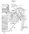
- FIG. 1 shows a partial view of a circuit breaker (LS switch) 1, which is arranged via two leads 2 and 3 in a circuit, not shown.
- the supply line 2 is electrically connected via a contact clip 4 with a fixed contact 5.
- the supply line 3 is electrically connected via conductors 6 and 7 to a contact arm 8, which carries a moving contact 9 end.
- the contact arm 8 is mounted pivotably about a rotation axis 10 such that in the closed position of the circuit breaker 1, not shown, the moving contact 9 rests on the fixed contact 5.
- the circuit is closed in this case via the supply line 2, the contact bracket 4, the fixed contact 5, the moving contact 9, the contact arm 8, the conductors 7 and 6 and the supply line 3.
- the LS-switch 1 is provided with a trigger shown only hinted 11, which emits a mechanical impulse to the contact arm 8 and a not-shown switching mechanism upon the occurrence of a predetermined trigger condition.
- a trigger condition for example, a short-circuit current can be set within the circuit.
- mechanical pulse of the contact arm 8 is pivoted in the open position shown in FIG 1.
- this pivoting of the contact arm 8 which can also be done manually in a conventional manner, the fixed contact 5 and the moving contact 9 are separated from each other.
- the moving contact 9 is arranged in its open position within a catching shoe 13.
- the trapping shoe 13 is formed substantially as a hollow cuboid of a conductive material.
- the catching shoe 13 is open at one of the fixed contact 5 facing side surface 14 and at one of the axis of rotation 10 of the contact arm 8 facing side surface 15, so that the interior 16 of the fishing boot 13 forms a pocket into which the contact arm 8 can be pivoted.
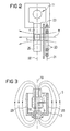
- the north-south axis 19 is at least approximately aligned with the axis of rotation 10 out.
- the north-south axis 19 thus runs approximately parallel to the contact arm 8 in its open position. In this way it is achieved that the static magnetic field S generated by the permanent magnet 18 (shown in FIG. 3) is approximately perpendicular to the arc gap 12.
- the fishing boot 13 is electrically connected to a blow coil 20, which in turn is electrically connected to the supply line 3.
- the blow coil 20 is wound in a coil plane 21 which is arranged parallel to a contact plane 22.
- the contact plane 22 is defined as the plane in which the contact arm 8 is pivotable, and which contains the contacts 5 and 9 and the arc gap 12.
- an insulating wall 23 is arranged between the inflation coil 20 and the contact plane 22. In this way it is prevented that the arc B rolls over the blow coil 20 and short circuits it.
- the LS switch 1 further comprises two rails 24 and 25, each near an end point of the arc gap 12 begin and extend from there to a quenching chamber 26. In this case, the distance between the rails 24,25 increases in their course to the quenching chamber 26 toward.
- the moving contact 9 associated with the first track 24 is electrically connected to the fishing boot 13.
- the second running rail 25 is formed from a remote from the trigger 11 and beyond the fixed contact 5 also extended part of the contact clip 4.
- the rails 24 and 25 thereby extend approximately within the contact plane 22.
- the area enclosed by the arc gap 12, the rails 24, 25 and the quenching chamber 26 is designated as the widening area 27 of the electric arc B.
- the magnetic field direction within the catching shoe 13 is approximately parallel to the north-south axis 19 of the permanent magnet 18.
- the arc B is displaced in the direction of a side wall 28 or 29 of the catching shoe 13 as a result of the Lorentz force F1.
- the direction of the Lorentz force F1 is - depending on the current flow direction within the arc B - either aligned with the side wall 28 or diametrically opposite to the opposite side wall 29.
- the arc B thus automatically switches on the bleaching coil 20, which now generates a magnetic field M which is approximately perpendicular to the contact plane 22. Under the influence of this magnetic field M, the arc B is acted upon by a further Lorentz force F2, which acts on the arc B in the direction of the rails 24,25. Under the action of the Lorentz force F2, the arc B jumps from the fixed contact 5 to the adjacent second running rail 25 or from the catching shoe 13 to the associated first running rail 24. Thereafter, the arc is fed along the extension region 27 to the quenching chamber 26, where the arc B is extinguished.
- the leads 2 and 3 are electrically isolated. Since in a reversal of the direction of current flow within the arc B, the direction of current flow inside the blow coil 20 and thus the direction of the magnetic field M reverses, the direction of the Lorentz force F2 depends only on the winding sense of the blow coil 20, but not from the current flow direction.
- the winding sense of the blow coil 20 is chosen such that the direction of the Lorentz force F2 is aligned with the expansion region 27 of the arc B.
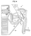
- FIG. 4 shows an advantageous development of the circuit breaker switch 1.
- the first running rail 24 is not connected directly to the catching shoe 13. Rather, an insulating gap 30 is formed between the running rail 24 and the fishing boot 13.
- the running rail 24 is connected by means of a separate line 31 to the supply line 3.
- This embodiment has the advantage that after skipping the arc B on the running rail 24, the puff 20 is de-energized. Another heating up the blow coil 20 and thus the LS switch 1 is thereby avoided.
Abstract
Description
Die Erfindung bezieht sich auf einen Leitungsschutzschalter oder auch Leistungsschalter mit einem Festkontakt und mit einem zur Herstellung einer schaltbaren elektrischen Verbindung zweier Zuleitungen gegen diesen verschwenkbaren Bewegkontakt sowie mit einer Blasspule zur magnetischen Beblasung eines bei der Trennung der Kontakte entstehenden elektrischen Lichtbogens.The invention relates to a circuit breaker or circuit breaker with a fixed contact and with a switchable for producing a switchable electrical connection of two leads against this moving contact and a blow coil for the magnetic blowing of a resulting in the separation of the contacts electric arc.
Ein bei einem Ausschaltvorgang eines Leitungsschutzschalters (LS-Schalter) entstehender elektrischer Lichtbogen ist in hohem Maße unerwünscht, da ein solcher einerseits auch nach dem Öffnen der Kontaktstelle den Stromfluß aufrechterhält und somit die Schaltzeit verlängert. Andererseits setzt der als Lichtbogen bezeichnete elektrische Funkenüberschlag eine vergleichsweise große Wärmemenge frei, die insbesondere zu einer starken Erhitzung der Schalterkontakte am Ansatzpunkt des Lichtbogens führt. Diese Erhitzung kann zu einer Schädigung oder Zerstörung der Kontakte führen. Es ist deshalb erforderlich, den unvermeidlicherweise bei einem Ausschaltprozeß entstehenden Lichtbogen möglichst schnell nach dessen Entstehen zu löschen.A resulting in a turn-off operation of a circuit breaker (LS-switch) electrical arc is highly undesirable because such a one hand, even after opening the contact point maintains the flow of current and thus extends the switching time. On the other hand, the electrical flashover, referred to as an arc, releases a comparatively large amount of heat, which in particular leads to a strong heating of the switch contacts at the point of application of the arc. This heating can lead to damage or destruction of the contacts. It is therefore necessary to extinguish the arc which inevitably occurs during a switch-off process as quickly as possible after it has arisen.
Zu diesem Zweck ist üblicherweise seitlich der Schalterkontakte eine Löscheinrichtung, insbesondere eine Löschkammer, vorgesehen. Um den Lichtbogen aus dem Kontaktbereich in die Löscheinrichtung zu treiben und somit den Aus-Schaltvorgang zu beschleunigen, wird der Lichtbogen häufig einem quer zur Lichtbogenstrecke wirkenden magnetischen Feldes ausgesetzt. Auf den aus bewegten Ladungsträgern bestehenden Lichtbogen wird bei richtiger Ausrichtung des Magnetfeldes eine als Lorentzkraft bezeichnete Kraft ausgeübt, die diesen in Richtung der Löscheinrichtung beschleunigt. Eine solche mittels eines Magnetfeldes erzwungene Wanderung des Lichtbogens wird als magnetische Beblasung bezeichnet.For this purpose, an extinguishing device, in particular an extinguishing chamber, is usually provided on the side of the switch contacts. In order to drive the arc out of the contact region into the extinguishing device and thus accelerate the switch-off process, the arc is frequently exposed to a magnetic field acting transversely to the arc gap. With the correct orientation of the magnetic field, a force known as the Lorentz force is exerted on the arc consisting of moving charge carriers, accelerating it in the direction of the extinguishing device. Such means A magnetic field forced migration of the arc is referred to as magnetic blowing.
Es ist insbesondere bei Gleichstromanwendungen üblich, das zur magnetischen Beblasung erforderliche Magnetfeld mittels eines nahe der Lichtbogenstrecke angeordneten Permanentmagneten zu erzeugen. Da ein Permanentmagnet ein statisches Magnetfeld erzeugt, ist die Wirksamkeit des LS-Schalters von der Richtung des durch diesen fließenden Stromes abhängig. Bei Umkehr des Stromflußrichtung kehrt sich nämlich auch die Richtung der auf den Lichtbogen wirkenden Lorentzkraft um. Dies bedeutet, daß bei einem Stromfluß entgegen der vorgesehenen Richtung der Lichtbogen nicht in die Löscheinrichtung getrieben wird, sondern von ihr weg. Beim Betrieb des LS-Schalters mit einem Wechselstrom wechselt auch die Lorentzkraft alternierend. Dies bewirkt in nachteiliger Weise eine gegenüber dem Gleichstrombetrieb erheblich gestörte Abschaltung.It is customary, in particular in DC applications, to generate the magnetic field required for magnetic blowing by means of a permanent magnet arranged close to the arc gap. Since a permanent magnet generates a static magnetic field, the effectiveness of the LS switch depends on the direction of the current flowing through it. In fact, when the current flow direction is reversed, the direction of the Lorentz force acting on the arc also reverses. This means that in a current flow contrary to the intended direction of the arc is not driven into the extinguishing device, but away from her. When operating the LS-switch with an alternating current also changes the Lorentz force alternately. This causes a disadvantageous compared to the DC operation significantly disturbed shutdown.
Bei einem sogenannten Allstrom-Leitungsschutzschalter, d.h. bei einem LS-Schalter, der polungsunabhängig für Gleichstrom und Wechselstrom geeignet ist, könnte der Einsatz einer mit einem Dauerstrom durchflossenen Magnetspule zur Beblasung vorgesehen werden. Diese Blasspule ist zwischen die Zuleitungen des LS-Schalters geschaltet, so daß der Netzstrom in der Blasspule ein einem Permanentmagneten vergleichbares Magnetfeld erzeugt. Eine Blasspule hat gegenüber einem Permanentmagneten den Vorteil, daß sich ihr Magnetfeld bei einer Umkehr der Stromflußrichtung ebenfalls umkehrt. Die gleichzeitige Invertierung des Stromflusses und der Magnetfeldrichtung bewirkt, daß die resultierende Lorentzkraft unabhängig von der jeweiligen Stromflußrichtung stets in dieselbe Richtung zeigt. Bei geeigneter Anordnung der Spule wird somit der Lichtbogen stets in die Löscheinrichtung getrieben.In a so-called all-current circuit breaker, i. in the case of a circuit-breaker which is polarity-independent suitable for direct current and alternating current, it would be possible to use a magnetic coil through which a continuous current flows for blowing. This blow coil is connected between the leads of the circuit breaker, so that the mains current in the blow coil generates a magnetic field comparable to a permanent magnet. A blow coil has the advantage over a permanent magnet that its magnetic field also reverses when the current flow direction is reversed. The simultaneous inversion of the current flow and the magnetic field direction causes the resulting Lorentz force always points in the same direction, regardless of the current flow direction. With a suitable arrangement of the coil thus the arc is always driven into the extinguishing device.
Der Einsatz einer dauerstromdurchflossenen Blasspule hat jedoch den Nachteil, daß sich die Blasspule infolge des Stromflusses stark erwärmt. Eine Erwärmung der Blasspule und somit des Innenraums des LS-Schalters ist jedoch unerwünscht. Ferner ist die Wirkung einer dauerstromdurchflossenen Blasspule vergleichsweise gering. Dies liegt daran, daß die Windungszahl der dauerstromdurchflossenen Blasspule aufgrund des im LS-Schalter vorhandenen Raumes gering gehalten werden muß.However, the use of a continuous current blown coil has the disadvantage that the blow coil due to the current flow strongly heated. However, heating the blow coil and thus the interior of the circuit breaker is undesirable. Furthermore, the effect of a blown through current blow coil is comparatively low. This is due to the fact that the number of turns of the blown coil through which the continuous current flows must be kept low due to the space present in the MCB switch.
Aus der GB 930 101 A ist ein Leitungsschutzschalter gemäß dem Oberbegriff des Anspruchs 1 bekannt. Der dort offenbarte Leitungsschutzschalter umfasst einen Festkontakt und einen zur Herstellung einer schaltbaren elektrischen Verbindung zweier Zuleitungen gegen diesen verschwenkbaren Bewegkontakt sowie eine Blasspule zur magnetischen Beblasung eines bei der Trennung der Kontakte entstehenden elektrischen Lichtbogens, wobei die Blasspule derart zwischen einer Zuleitung und einem Kontaktelement zur Ankopplung an den Lichtbogen geschaltet ist, daß nach Trennung der Kontakte eine elektrische Verbindung der Zuleitungen über den Lichtbogen und die Blasspule erfolgt.From GB 930 101 A a circuit breaker according to the preamble of claim 1 is known. The circuit breaker disclosed therein comprises a fixed contact and a switchable for making a switchable electrical connection of two leads against this moving contact and a blow coil for magnetic blowing of a resulting in the separation of the contacts electric arc, the blow coil between such a supply line and a contact element for coupling the arc is connected, that after disconnection of the contacts, an electrical connection of the leads via the arc and the blow coil takes place.
Der Erfindung liegt die Aufgabe zugrunde, einen Leitungsschutzschalter mit einer von der Stromflußrichtung unabhängigen und besonders effektiven magnetischen Beblasung eines elektrischen Lichtbogens anzugeben.The invention has for its object to provide a circuit breaker with an independent of the Stromflußrichtung and particularly effective magnetic blowing of an electric arc.
Diese Aufgabe wird erfindungsgemäß gelöst durch die Merkmale des Anspruchs 1. Danach ist zur magnetischen Beblasung des Lichtbogens eine Blasspule vorgesehen, die einerseits an eine Zuleitung, insbesondere die dem Bewegkontakt zugeordnete Zuleitung, angeschlossen ist. Andererseits ist die Blasspule mit einem Kontaktelement verbunden, welches als Ableitung für den Lichtbogen vorgesehen ist. Das Kontaktelement ist derart ausgebildet, daß nach Trennung der Kontakte der Lichtbogen am Kontaktelement angreift. Die Blasspule ist derart geschaltet, daß über den Lichtbogen und die Blasspule die beiden Zuleitungen leitend verbunden sind. Das Kontaktelement ist als den Bewegkontakt in dessen Öffnungsstellung zumindest seitlich bezüglich einer Lichtbogenstrecke umgebender Fangschuh ausgebildet.This object is achieved by the features of claim 1. Thereafter, a blow coil is provided for the magnetic blowing of the arc, on the one hand to a supply line, in particular the moving contact associated feed line is connected. On the other hand, the blow coil is connected to a contact element, which is provided as a derivative for the arc. The contact element is designed such that after separation of the contacts, the arc acts on the contact element. The blow coil is switched such that the two leads are conductively connected via the arc and the blow coil. The contact element is at least laterally as the moving contact in its open position formed with respect to an arc gap surrounding fishing shoe.
Die Erfindung geht dabei von der Überlegung aus, daß eine magnetische Beblasung bei einem Allstrom-Leitungsschutzschalter dann besonders effektiv wirkt, wenn sich die Richtung des Magnetfeldes stets mit der Stromflußrichtung innerhalb des Lichtbogens ändert. Sie nutzt die Erfahrung, daß eine solche stromflußabhängige Magnetfeldänderung vorteilhaft mittels einer Blasspule erzielt wird. Dabei könnte eine Verbesserung gegenüber einer herkömmlichen Blasspule erzielt werden, wenn die Blasspule lediglich bei einem bestehenden Lichtbogen betrieben, d.h. von Strom durchflossen, würde. Zu allen anderen Zeiten sollte dagegen ein Stromfluß durch die Blasspule unterbunden sein, um einen unnötigen Leistungsumsatz und damit eine unerwünschte Wärmeentwicklung zu verhindern. Erkanntermaßen wird der beschriebene Effekt erzielt, wenn die Blasspule mittels des Lichtbogens kontaktiert wird. Der Lichtbogen wirkt hierbei quasi als Schalter, der die Blasspule nur dann zuschaltet, wenn der Lichtbogen vorhanden ist.The invention is based on the consideration that a magnetic blowing in an all-current circuit breaker is particularly effective when the direction of the magnetic field always changes with the Stromflußrichtung within the arc. It uses the experience that such a flow-dependent magnetic field change is advantageously achieved by means of a blow coil. In this case, an improvement over a conventional blinding coil could be achieved if the blown coil operated only in an existing arc, i. E. flowed through by electricity would. At all other times, however, a flow of current through the puff coil should be prevented in order to prevent unnecessary power consumption and thus unwanted heat generation. As is known, the described effect is achieved when the puff is contacted by the arc. The arc acts as a kind of switch that only switches on the blower coil when the arc is present.
Aufgrund des lichtbogenbetätigten, und deshalb nur kurzzeitigen Stromflusses durch die Blasspule, ist die während des Abschaltvorgangs in der Blasspule umgesetzte elektrische Leistung vernachlässigbar gering. Infolgedessen kann bei vergleichsweise kleinem Drahtdurchmesser eine hohe Windungszahl der lichtbogenbetätigten Blasspule verwirklicht werden, wodurch die Wirkung erheblich höher als die Wirkung einer herkömmlichen dauerstromdurchflossenen Blasspule ist. Infolge des nur kurzzeitigen Stromes wird die Blasspule nur geringfügig erwärmt.Due to the arc-actuated, and therefore only short-term current flow through the blow coil, the converted during the shutdown in the blow coil electrical power is negligible. As a result, with a comparatively small wire diameter, a high number of turns of the arc-operated blow coil can be realized, whereby the effect is considerably higher than the effect of a conventional continuous-current blown coil. Due to the short-term current, the blow coil is only slightly heated.
Aufgrund der Ausbildung des Kontaktelements in Form eines Fangschuhs, welcher den Bewegkontakt in dessen Öffnungsstellung zumindest seitlich bezüglich der Lichtbogenstrecke umgibt, taucht der Bewegkontakt in dessen Öffnungsstellung in den Fangschuh ein, wobei der Lichtbogen vom Bewegkontakt auf den Fangschuh überspringt und auf diese Weise das Blasfeld einschaltet.Due to the design of the contact element in the form of a catching shoe, which surrounds the moving contact in the open position at least laterally with respect to the arc gap, the moving contact immersed in its open position in the catching shoe, wherein the arc from the moving contact on skip the fishing shoe and turn on the blower field in this way.
Vorteilhafterweise ist das Kontaktelement mit einem Permanentmagneten versehen, der ein zur Lichtbogenstrecke etwa senkrechtes Magnetfeld erzeugt und somit den Lichtbogen in Richtung des Kontaktelements ablenkt. Auf diese Weise wird das Überspringen des Lichtbogens auf das Kontaktelement erheblich beschleunigt.Advantageously, the contact element is provided with a permanent magnet, which generates a magnetic field approximately perpendicular to the magnetic field and thus deflects the arc in the direction of the contact element. In this way, the skipping of the arc to the contact element is significantly accelerated.
Zur Verkürzung der Schaltzeit umfaßt der LS-Schalter in zweckmäßiger Ausgestaltung zwei Laufschienen, die den Lichtbogen aus dem Bereich der Kontakte einer Löschkammer zuführen. Der zwischen den Laufschienen gebildete Bereich ist als Ausweitungsbereich des Lichtbogens bezeichnet.In order to shorten the switching time, the LS switch in an expedient embodiment comprises two rails, which feed the arc from the region of the contacts of a quenching chamber. The area formed between the rails is referred to as the expansion area of the arc.
Mittels einer parallel zum Ausweitungsbereich des Lichtbogens gewickelten Blasspule wird zweckmäßigerweise eine besonders effektive Beblasung des Lichtbogens erreicht. Bevorzugt ist dabei zwischen dem Ausweitungsbereich des Lichtbogens und der Blasspule eine Isolierwand angeordnet, die ein Überschlagen des Lichtbogens auf die Blasspule verhindert.By means of a wound parallel to the extension region of the arc blinding coil a particularly effective blowing of the arc is advantageously achieved. In this case, an insulating wall is preferably arranged between the expansion region of the arc and the blow coil, which prevents a rollover of the arc to the blow coil.
In einer besonders zweckmäßigen Ausführungsform schließt dabei eine erste Laufschiene elektrisch leitend an das Kontaktelement an. Die elektrische Anbindung der ersten Laufschiene an das Kontaktelement begünstigt das Überspringen des Lichtbogens vom Kontaktelement auf die Laufschiene. In einer vorteilhaften Alternativausführung ist die erste Laufschiene lediglich bis auf einen Isolierabstand an das Kontaktelement herangeführt und über eine zur Blasspule parallelverlaufenden Leitung mit der korrespondierenden Zuleitung verbunden. Auf diese Weise wird die Blasspule lediglich eingeschaltet, um den Lichtbogen vom Kontaktelement auf die Laufschienen zu treiben. In dieser Ausführung ist der Stromfluß durch die Blasspule unterbrochen, sobald der Lichtbogen auf die Laufschienen übergesprungen ist. Eine Aufheizung der Blasspule durch die in ihr umgesetzte elektrische Leistung ist somit weiter reduziert. Die Blasspule kann dadurch besonders platzsparend realisiert werden.In a particularly expedient embodiment, a first running rail connects electrically conductively to the contact element. The electrical connection of the first rail to the contact element favors the skipping of the arc from the contact element on the running rail. In an advantageous alternative embodiment, the first running rail is only brought up to an insulating distance to the contact element and connected via a line parallel to the blow coil line with the corresponding supply line. In this way, the blow coil is only turned on to drive the arc from the contact element on the rails. In this embodiment, the current flow through the blower coil is interrupted as soon as the arc has jumped over the rails. Heating the blown coil by the electrical power converted into it is thus further reduced. The blower coil can be realized in a particularly space-saving way.
Die mit der Erfindung erzielten Vorteile bestehen insbesondere darin, daß mittels einer lichtbogenbetätigten Blasspule eine besonders effektive magnetische Beblasung eines Lichtbogens stattfindet, da die Blasspule nur im Bedarfsfall, d.h. bei Auftreten eines Lichtbogens in Betrieb ist. Vorteilhafterweise ist die Richtung der Lorentzkraft dabei lediglich vom Wicklungssinn der Blasspule abhängig, nicht aber von der Stromflußrichtung innerhalb des Lichtbogens.The advantages achieved by the invention are in particular that a particularly effective magnetic blowing of an arc takes place by means of an arc-operated blow coil, since the blow coil only in case of need, i. when an arc occurs in operation. Advantageously, the direction of the Lorentz force only depends on the winding sense of the blow coil, but not on the current flow direction within the arc.
Nachfolgend werden Ausführungsbeispiele der Erfindung anhand einer Zeichnung näher erläutert. Dabei zeigen:
- FIG 1
- eine Teilansicht eines Leitungsschutzschalters mit einem Festkontakt, einem Bewegkontakt und einer Blasspule,
- FIG 2
- einen Schnitt II-II durch den Leitungsschutzschalter gemäß FIG 1,
- FIG 3
- einen Schnitt III-III durch den Leitungsschutzschalter gemäß FIG 1, und
- FIG 4
- in einer Darstellung gemäß FIG 1 eine alternative Ausführungsform des Leitungsschutzschalters.
- FIG. 1
- a partial view of a circuit breaker with a fixed contact, a moving contact and a blow coil,
- FIG. 2
- a section II-II through the circuit breaker according to FIG 1,
- FIG. 3
- a section III-III through the circuit breaker according to FIG 1, and
- FIG. 4
- in an illustration according to FIG 1, an alternative embodiment of the circuit breaker.
FIG 1 zeigt in einer Teilansicht einen Leitungsschutzschalter (LS-Schalter) 1, der über zwei Zuleitungen 2 und 3 in einem nicht näher dargestellten Stromkreis angeordnet ist. Die Zuleitung 2 ist über einen Kontaktbügel 4 mit einem Festkontakt 5 elektrisch leitend verbunden. Die Zuleitung 3 ist über Leiter 6 und 7 elektrisch an einen Kontaktarm 8 angeschlossen, der endseitig einen Bewegkontakt 9 trägt. Der Kontaktarm 8 ist dabei um eine Drehachse 10 derart schwenkbar gelagert, daß in der nicht dargestellten Schließstellung des Leitungsschutzschalters 1 der Bewegkontakt 9 auf dem Festkontakt 5 aufliegt. Der Stromkreis ist in diesem Fall über die Zuleitung 2, den Kontaktbügel 4, den Festkontakt 5, den Bewegkontakt 9, den Kontaktarm 8, die Leiter 7 und 6 und die Zuleitung 3 geschlossen.1 shows a partial view of a circuit breaker (LS switch) 1, which is arranged via two
Der LS-Schalter 1 ist mit einem nur andeutungsweise dargestellten Auslöser 11 versehen, der bei Eintreten einer vorgegebenen Auslösebedingung einen mechanischen Impuls an den Kontaktarm 8 und ein nicht näher dargestelltes Schaltschloß abgibt. Als Auslösebedingung kann beispielsweise ein Kurzschlußstrom innerhalb des Stromkreises festgelegt sein. Infolge des vom Auslöser 11 an den Kontaktarm 8 abgegebenen mechanischen Impulses wird der Kontaktarm 8 in die gemäß FIG 1 dargestellte Öffnungsstellung verschwenkt. Infolge dieser Verschwenkung des Kontaktarmes 8, die in an sich bekannter Weise auch manuell erfolgen kann, werden der Festkontakt 5 und der Bewegkontakt 9 voneinander getrennt. Bei der sukzessiven Auseinanderbewegung des Festkontaktes 5 und des Bewegungskontaktes 9 entsteht ein sogenannter elektrischer Lichtbogen B, bei dem durch Ionisation der sich zwischen den Kontakten 5 und 9 befindenden Luft der Stromfluß zwischen den Zuleitungen 2 und 3 aufrechterhalten wird. Der Lichtbogen verläuft näherungsweise entlang der Verbindungslinie der Kontakte 5 und 9 in deren Öffnungsstellung. Diese Strecke ist daher als Lichtbogenstrecke 12 bezeichnet.The LS-switch 1 is provided with a trigger shown only hinted 11, which emits a mechanical impulse to the
Der Bewegkontakt 9 ist in seiner Öffnungsstellung innerhalb eines Fangschuhs 13 angeordnet. Der Fangschuh 13 ist im wesentlichen als Hohlquader aus einem leitfähigen Material ausgebildet. Der Fangschuh 13 ist dabei an einer dem Festkontakt 5 zugewandten Seitenfläche 14 sowie an einer der Drehachse 10 des Kontaktarmes 8 zugewandten Seitenfläche 15 offen, so daß der Innenraum 16 des Fangschuhs 13 eine Tasche bildet, in die der Kontaktarm 8 einschwenkbar ist. An der der Drehachse 10 abgewandten Seitenfläche 17 trägt der Fangschuh 13 einen Permanentmagneten 18, dessen Nord-Süd-Achse 19 zumindest annähernd zur Drehachse 10 hin ausgerichtet ist. Die Nord-Süd-Achse 19 verläuft somit etwa parallel zum Kontaktarm 8 in dessen Öffnungsstellung. Auf diese Weise wird erreicht, daß das vom Permanentmagneten 18 erzeugte (in Fig. 3 dargestellte) statische Magnetfeld S etwa senkrecht auf der Lichtbogenstrecke 12 steht.The moving contact 9 is arranged in its open position within a catching
Der Fangschuh 13 ist elektrisch an eine Blasspule 20 angeschlossen, die wiederum mit der Zuleitung 3 elektrisch verbunden ist. Wie aus einer Zusammenschau der Figuren 1 und 2 ersichtlich ist, ist die Blasspule 20 in einer Spulenebene 21 gewickelt, die parallel zu einer Kontaktebene 22 angeordnet ist. Die Kontaktebene 22 ist dabei definiert als die Ebene, in welcher der Kontaktarm 8 schwenkbar ist, und die die Kontakte 5 und 9 sowie die Lichtbogenstrecke 12 enthält. Zwischen der Blasspule 20 und der Kontaktebene 22 ist eine Isolierwand 23 angeordnet. Auf diese Weise wird verhindert, daß der Lichtbogen B auf die Blasspule 20 überschlägt und diese kurzschließt.The
Der LS-Schalter 1 umfaßt desweiteren zwei Laufschienen 24 und 25, die in der Nähe jeweils eines Endpunktes der Lichtbogenstrecke 12 beginnen und sich von dort bis zu einer Löschkammer 26 erstrecken. Dabei nimmt der Abstand zwischen den Laufschienen 24,25 in deren Verlauf zur Löschkammer 26 hin zu. Die dem Bewegkontakt 9 zugeordnete erste Laufschiene 24 ist dabei elektrisch leitend an den Fangschuh 13 angesetzt. Die zweite Laufschiene 25 ist aus einem vom Auslöser 11 abgewandten und über den Festkontakt 5 hinaus verlängerten Teil des Kontaktbügels 4 gebildet. Die Laufschienen 24 und 25 erstrekken sich dabei etwa innerhalb der Kontaktebene 22. Die von der Lichtbogenstrecke 12, den Laufschienen 24,25 und der Löschkammer 26 eingeschlossene Fläche ist als Ausweitungsbereich 27 des Lichtbogens B bezeichnet.The LS switch 1 further comprises two
Beim Trennen der Kontakte 5 und 9 entsteht der Lichtbogen B - wie in FIG 1 angedeutet - entlang der Lichtbogenstrecke 12 zwischen dem Festkontakt 5 und dem Bewegkontakt 9. In der Umgebung des Bewegkontaktes 9 gerät der Lichtbogen B in Einfluß des in FIG 3 skizzierten statischen Magnetfeldes S des Permanentmagneten 18. Auf den aus bewegten Ladungsträgern bestehenden Lichtbogen B wird mittels des Magnetfeldes S eine Lorentzkraft F1 senkrecht zur Lichtbogenstrecke 12 sowie senkrecht zur innerhalb des Fangschuhs 13 vorherrschende Magnetfeldrichtung ausgeübt.When separating the
Wie aus FIG 3 hervorgeht, ist die Magnetfeldrichtung innerhalb des Fangschuhs 13 etwa parallel zur Nord-Süd-Achse 19 des Permanentmagneten 18. Der Lichtbogen B wird infolge der Lorentzkraft F1 in Richtung einer Seitenwand 28 oder 29 des Fangschuhs 13 verdrängt. Die Richtung der Lorentzkraft F1 ist - abhängig von der Stromflußrichtung innerhalb des Lichtbogens B - entweder auf die Seitenwand 28 oder diametral entgegengesetzt auf die gegenüberliegende Seitenwand 29 ausgerichtet. Nach dem Überspringen des Lichtbogens B auf die Seitenwand 28 oder 29 erfolgt der Stromfluß nunmehr über den Festkontakt 5 und den Lichtbogen B sowie über den Fangschuh 13. Von dort wird er über die Blasspule 20 an die Zuleitung 3 geleitet. Der Lichtbogen B schaltet somit selbsttätig die Blasspule 20 ein, die nunmehr ein zur Kontaktebene 22 etwa senkrechtes Magnetfeld M erzeugt. Unter dem Einfluß dieses Magnetfeldes M wird der Lichtbogen B mit einer weiteren Lorentzkraft F2 beaufschlagt, die den Lichtbogen B in Richtung der Laufschienen 24,25 beaufschlagt. Unter der Wirkung der Lorentzkraft F2 springt der Lichtbogen B von dem Festkontakt 5 auf die angrenzende zweite Laufschiene 25 bzw. von dem Fangschuh 13 auf die zugehörige erste Laufschiene 24 über. Hierauf wird der Lichtbogen entlang des Ausweitungsbereiches 27 der Löschkammer 26 zugeführt, wo der Lichtbogen B gelöscht wird.As can be seen from FIG. 3, the magnetic field direction within the catching
Nach dem Löschen des Lichtbogens B sind die Zuleitungen 2 und 3 elektrisch getrennt. Da sich bei einer Umkehr der Stromflußrichtung innerhalb des Lichtbogens B auch die Stromflußrichtung innerhalb der Blasspule 20 und somit die Richtung des Magnetfeldes M umkehrt, hängt die Richtung der Lorentzkraft F2 lediglich vom Wicklungssinn der Blasspule 20, nicht aber von der Stromflußrichtung ab. Der Wicklungssinn der Blasspule 20 ist dabei derart gewählt, daß die Richtung der Lorentzkraft F2 auf den Ausweitungsbereich 27 des Lichtbogens B ausgerichtet ist.After extinguishing the arc B, the
FIG 4 zeigt eine vorteilhafte Weiterbildung des LS-Schalters 1. Im Unterschied zu der Ausführungsform gemäß FIG 1 ist hierbei die erste Laufschiene 24 nicht direkt mit dem Fangschuh 13 verbunden. Vielmehr ist zwischen der Laufschiene 24 und dem Fangschuh 13 ein Isolierabstand 30 gebildet. Die Laufschiene 24 ist mittels einer separaten Leitung 31 an die Zuleitung 3 angeschlossen. Diese Ausführung hat den Vorteil, daß nach dem Überspringen des Lichtbogens B auf die Laufschiene 24 die Blasspule 20 stromlos ist. Eine weitere Aufheizung der Blasspule 20 und somit des LS-Schalters 1 ist hierdurch vermieden.4 shows an advantageous development of the circuit breaker switch 1. In contrast to the embodiment according to FIG. 1, the first running
Claims (7)
- Circuit breaker having a fixed contact (5) and a moving contact (9) which can be pivoted against same for establishing a switchable electrical connection of two leads (2,3), and a blowout coil (20) for magnetic blowout of an electric arc (B) produced when the contacts (5,9) are separated, the blowout coil (20) being connected between a lead (3) and a contact element (13) for coupling to the arc (B) in such a way that after separation of the contacts (5,9) the leads (2,3) are electrically connected via the arc (B) and the blowout coil (20),
characterised in that the contact element is implemented as a catching shoe (13) enclosing the moving contact (9) in its open position at least laterally in respect of an arc gap (12). - Circuit breaker according to claim 1,
characterised in that the contact element (13) is provided with a permanent magnet (18) which produces a magnetic field (S) approximately perpendicular to an arc gap (12). - Circuit breaker according to one of claims 1 and 2,
characterised by two runners (24,25), electrically connected to respective leads (2,3), for guiding the arc (B) to an arc chute (26), the expansion region (27) of the arc (B), formed between the runners (24,25), widening out towards the arc chute (26). - Circuit breaker according to claim 3,
characterised in that the blowout coil (20) is wound in a coil plane (21) parallel to the expansion region (27) of the arc (B). - Circuit breaker according to claim 3 or 4,
characterised in that, for its contacting, a first runner (24) is attached in an electrically conductive manner to the contact element (13). - Circuit breaker according to claim 3 or 4,
characterised in that an insulating clearance (30) is formed between a first runner (24) assigned to the contact element (13) and the contact element (13). - Circuit breaker according to one of claims 1 to 6,
characterised in that an insulating wall (23) is disposed between the blowout coil (20) and the contacts (5, 9).
Applications Claiming Priority (2)
| Application Number | Priority Date | Filing Date | Title |
|---|---|---|---|
| DE19836829 | 1998-08-13 | ||
| DE19836829 | 1998-08-13 |
Publications (3)
| Publication Number | Publication Date |
|---|---|
| EP0980085A2 EP0980085A2 (en) | 2000-02-16 |
| EP0980085A3 EP0980085A3 (en) | 2000-08-02 |
| EP0980085B1 true EP0980085B1 (en) | 2006-11-22 |
Family
ID=7877497
Family Applications (1)
| Application Number | Title | Priority Date | Filing Date |
|---|---|---|---|
| EP99115328A Expired - Lifetime EP0980085B1 (en) | 1998-08-13 | 1999-08-03 | Power circuit breaker with blast coil operated by the arc |
Country Status (4)
| Country | Link |
|---|---|
| EP (1) | EP0980085B1 (en) |
| AT (1) | ATE346366T1 (en) |
| DE (1) | DE59913992D1 (en) |
| ES (1) | ES2276490T3 (en) |
Cited By (3)
| Publication number | Priority date | Publication date | Assignee | Title |
|---|---|---|---|---|
| US7417520B2 (en) | 2006-08-01 | 2008-08-26 | Schaltbau Gmbh | Contactor for direct current and alternating current operation |
| DE102007054960B3 (en) * | 2007-11-17 | 2009-04-23 | Moeller Gmbh | Switching device for DC applications |
| EP2061053A2 (en) | 2007-11-17 | 2009-05-20 | Moeller GmbH | Switching device for direct current applications |
Families Citing this family (5)
| Publication number | Priority date | Publication date | Assignee | Title |
|---|---|---|---|---|
| DE10352934B4 (en) * | 2003-11-11 | 2005-12-22 | Siemens Ag | Arc-extinguishing device |
| EP2393096B1 (en) * | 2010-06-07 | 2013-02-13 | ABB Schweiz AG | Easy to interrupt low voltage circuit breaker, in particular current protection switch |
| DE102010031907B9 (en) * | 2010-07-22 | 2013-01-17 | Schaltbau Gmbh | Unidirectional switching DC contactor |
| EP2642500A1 (en) * | 2012-03-21 | 2013-09-25 | Eaton Industries GmbH | DC circuit without arcing chambers |
| US10510506B1 (en) * | 2019-01-31 | 2019-12-17 | Carling Technologies, Inc. | Narrow profile circuit breaker with arc interruption |
Family Cites Families (5)
| Publication number | Priority date | Publication date | Assignee | Title |
|---|---|---|---|---|
| GB930101A (en) * | 1958-08-02 | 1963-07-03 | Whipp & Bourne Ltd | Improvements in or relating to air-break circuit-breakers |
| US3155801A (en) * | 1960-12-21 | 1964-11-03 | Ite Circuit Breaker Ltd | Arc chute side with encapsulated face wound blowout coil |
| DE2841004C2 (en) * | 1978-09-21 | 1980-10-02 | Licentia Gmbh | Circuit breaker with additional blow loop |
| DE3023673A1 (en) * | 1980-06-25 | 1982-01-14 | Deutsche Forschungs- und Versuchsanstalt für Luft- und Raumfahrt e.V., 5300 Bonn | METHOD FOR DELETING THE Tear-off Sheet IN SWITCHES AND MAGNETIC FIELD ARRANGEMENT IN THE CATHODE AREA OF A SWITCH FOR CARRYING OUT THIS METHOD |
| US4451718A (en) * | 1981-02-27 | 1984-05-29 | Mitsubishi Denki Kabushiki Kaisha | Circuit breaker |
-
1999
- 1999-08-03 AT AT99115328T patent/ATE346366T1/en not_active IP Right Cessation
- 1999-08-03 EP EP99115328A patent/EP0980085B1/en not_active Expired - Lifetime
- 1999-08-03 DE DE59913992T patent/DE59913992D1/en not_active Expired - Lifetime
- 1999-08-03 ES ES99115328T patent/ES2276490T3/en not_active Expired - Lifetime
Cited By (6)
| Publication number | Priority date | Publication date | Assignee | Title |
|---|---|---|---|---|
| US7417520B2 (en) | 2006-08-01 | 2008-08-26 | Schaltbau Gmbh | Contactor for direct current and alternating current operation |
| DE102007054960B3 (en) * | 2007-11-17 | 2009-04-23 | Moeller Gmbh | Switching device for DC applications |
| EP2061053A2 (en) | 2007-11-17 | 2009-05-20 | Moeller GmbH | Switching device for direct current applications |
| EP2061052A2 (en) | 2007-11-17 | 2009-05-20 | Moeller GmbH | Switching device for direct current applications |
| DE102007054958A1 (en) | 2007-11-17 | 2009-06-04 | Moeller Gmbh | Switching device for DC applications |
| EP2383761A1 (en) | 2007-11-17 | 2011-11-02 | Eaton Industries GmbH | Switching device for direct current applications |
Also Published As
| Publication number | Publication date |
|---|---|
| EP0980085A2 (en) | 2000-02-16 |
| ATE346366T1 (en) | 2006-12-15 |
| ES2276490T3 (en) | 2007-06-16 |
| EP0980085A3 (en) | 2000-08-02 |
| DE59913992D1 (en) | 2007-01-04 |
Similar Documents
| Publication | Publication Date | Title |
|---|---|---|
| DE102011118418B4 (en) | switching system | |
| EP2079088A2 (en) | Switching device, in particular voltage switching device with two switched switch contact pairs arrayed in a row for interrupting an electricity flow. | |
| EP3766090B1 (en) | Circuit breaker for isolating an electrical circuit | |
| EP0980085B1 (en) | Power circuit breaker with blast coil operated by the arc | |
| DE102011089234B4 (en) | Arc extinguishing device and circuit breaker | |
| DE10352934B4 (en) | Arc-extinguishing device | |
| EP0039096B1 (en) | Puffer type gas-blast circuit interrupter | |
| DE3141324A1 (en) | CIRCUIT BREAKER | |
| DE1640262B2 (en) | CURRENT LIMITING SWITCH | |
| EP0515009B1 (en) | Multi-position rotary switch with extinguishing gas | |
| DE19629867C2 (en) | Current limiting circuit breaker | |
| DE939460C (en) | Electric switch | |
| EP2541574B1 (en) | Double interrupter protective switch device | |
| EP0884747A2 (en) | Switchgear for an electric installation | |
| DE19524915A1 (en) | Arc-quench arrangement esp for line circuit breaker - has portions of conductive loop extending along both arc guide rails and between them across face or back of arc-quench chamber. | |
| EP3602593B1 (en) | Switch device with improved permanent magnetic arc extinction | |
| EP3607572B1 (en) | Switch device with contact cover | |
| EP0255008B1 (en) | Automatic cut-out | |
| DE3803849C1 (en) | High-power switching path for protective switching devices | |
| DE102009035299B4 (en) | Contact system and switching device | |
| EP0624889B1 (en) | Electric switch | |
| EP1056105A2 (en) | Electrical installation device, particularly a circuit breaker | |
| DE102011080525A1 (en) | Double protective switching device e.g. circuit breaker switch, has chambers for extinguishing arcs formed during opening of switching contacts such that arcs are oriented in opposite directions in one phase of arc formation | |
| DE19757179B4 (en) | Electrodynamically acted upon contact system | |
| DE102016213073A1 (en) | switching system |
Legal Events
| Date | Code | Title | Description |
|---|---|---|---|
| PUAI | Public reference made under article 153(3) epc to a published international application that has entered the european phase |
Free format text: ORIGINAL CODE: 0009012 |
|
| AK | Designated contracting states |
Kind code of ref document: A2 Designated state(s): AT BE CH CY DE DK ES FI FR GB GR IE IT LI LU MC NL PT SE |
|
| AX | Request for extension of the european patent |
Free format text: AL;LT;LV;MK;RO;SI |
|
| PUAL | Search report despatched |
Free format text: ORIGINAL CODE: 0009013 |
|
| AK | Designated contracting states |
Kind code of ref document: A3 Designated state(s): AT BE CH CY DE DK ES FI FR GB GR IE IT LI LU MC NL PT SE |
|
| AX | Request for extension of the european patent |
Free format text: AL;LT;LV;MK;RO;SI |
|
| 17P | Request for examination filed |
Effective date: 20000818 |
|
| AKX | Designation fees paid |
Free format text: AT BE CH CY DE DK ES FI FR GB GR IE IT LI LU MC NL PT SE |
|
| GRAP | Despatch of communication of intention to grant a patent |
Free format text: ORIGINAL CODE: EPIDOSNIGR1 |
|
| GRAS | Grant fee paid |
Free format text: ORIGINAL CODE: EPIDOSNIGR3 |
|
| GRAA | (expected) grant |
Free format text: ORIGINAL CODE: 0009210 |
|
| AK | Designated contracting states |
Kind code of ref document: B1 Designated state(s): AT BE CH CY DE DK ES FI FR GB GR IE IT LI LU MC NL PT SE |
|
| PG25 | Lapsed in a contracting state [announced via postgrant information from national office to epo] |
Ref country code: NL Free format text: LAPSE BECAUSE OF FAILURE TO SUBMIT A TRANSLATION OF THE DESCRIPTION OR TO PAY THE FEE WITHIN THE PRESCRIBED TIME-LIMIT Effective date: 20061122 Ref country code: IE Free format text: LAPSE BECAUSE OF FAILURE TO SUBMIT A TRANSLATION OF THE DESCRIPTION OR TO PAY THE FEE WITHIN THE PRESCRIBED TIME-LIMIT Effective date: 20061122 Ref country code: FI Free format text: LAPSE BECAUSE OF FAILURE TO SUBMIT A TRANSLATION OF THE DESCRIPTION OR TO PAY THE FEE WITHIN THE PRESCRIBED TIME-LIMIT Effective date: 20061122 |
|
| REG | Reference to a national code |
Ref country code: GB Ref legal event code: FG4D Free format text: NOT ENGLISH |
|
| REG | Reference to a national code |
Ref country code: CH Ref legal event code: EP |
|
| GBT | Gb: translation of ep patent filed (gb section 77(6)(a)/1977) |
Effective date: 20061127 |
|
| REG | Reference to a national code |
Ref country code: IE Ref legal event code: FG4D Free format text: LANGUAGE OF EP DOCUMENT: GERMAN |
|
| REF | Corresponds to: |
Ref document number: 59913992 Country of ref document: DE Date of ref document: 20070104 Kind code of ref document: P |
|
| PG25 | Lapsed in a contracting state [announced via postgrant information from national office to epo] |
Ref country code: SE Free format text: LAPSE BECAUSE OF FAILURE TO SUBMIT A TRANSLATION OF THE DESCRIPTION OR TO PAY THE FEE WITHIN THE PRESCRIBED TIME-LIMIT Effective date: 20070222 Ref country code: DK Free format text: LAPSE BECAUSE OF FAILURE TO SUBMIT A TRANSLATION OF THE DESCRIPTION OR TO PAY THE FEE WITHIN THE PRESCRIBED TIME-LIMIT Effective date: 20070222 |
|
| PG25 | Lapsed in a contracting state [announced via postgrant information from national office to epo] |
Ref country code: PT Free format text: LAPSE BECAUSE OF FAILURE TO SUBMIT A TRANSLATION OF THE DESCRIPTION OR TO PAY THE FEE WITHIN THE PRESCRIBED TIME-LIMIT Effective date: 20070423 |
|
| NLV1 | Nl: lapsed or annulled due to failure to fulfill the requirements of art. 29p and 29m of the patents act | ||
| ET | Fr: translation filed | ||
| REG | Reference to a national code |
Ref country code: ES Ref legal event code: FG2A Ref document number: 2276490 Country of ref document: ES Kind code of ref document: T3 |
|
| REG | Reference to a national code |
Ref country code: IE Ref legal event code: FD4D |
|
| PLBE | No opposition filed within time limit |
Free format text: ORIGINAL CODE: 0009261 |
|
| STAA | Information on the status of an ep patent application or granted ep patent |
Free format text: STATUS: NO OPPOSITION FILED WITHIN TIME LIMIT |
|
| 26N | No opposition filed |
Effective date: 20070823 |
|
| BERE | Be: lapsed |
Owner name: SIEMENS A.G. Effective date: 20070831 |
|
| REG | Reference to a national code |
Ref country code: CH Ref legal event code: PL |
|
| PG25 | Lapsed in a contracting state [announced via postgrant information from national office to epo] |
Ref country code: MC Free format text: LAPSE BECAUSE OF NON-PAYMENT OF DUE FEES Effective date: 20070831 Ref country code: LI Free format text: LAPSE BECAUSE OF NON-PAYMENT OF DUE FEES Effective date: 20070831 Ref country code: GR Free format text: LAPSE BECAUSE OF FAILURE TO SUBMIT A TRANSLATION OF THE DESCRIPTION OR TO PAY THE FEE WITHIN THE PRESCRIBED TIME-LIMIT Effective date: 20070223 Ref country code: CH Free format text: LAPSE BECAUSE OF NON-PAYMENT OF DUE FEES Effective date: 20070831 |
|
| PG25 | Lapsed in a contracting state [announced via postgrant information from national office to epo] |
Ref country code: BE Free format text: LAPSE BECAUSE OF NON-PAYMENT OF DUE FEES Effective date: 20070831 |
|
| PG25 | Lapsed in a contracting state [announced via postgrant information from national office to epo] |
Ref country code: AT Free format text: LAPSE BECAUSE OF NON-PAYMENT OF DUE FEES Effective date: 20070803 |
|
| PG25 | Lapsed in a contracting state [announced via postgrant information from national office to epo] |
Ref country code: LU Free format text: LAPSE BECAUSE OF NON-PAYMENT OF DUE FEES Effective date: 20070803 Ref country code: CY Free format text: LAPSE BECAUSE OF FAILURE TO SUBMIT A TRANSLATION OF THE DESCRIPTION OR TO PAY THE FEE WITHIN THE PRESCRIBED TIME-LIMIT Effective date: 20061122 |
|
| PGFP | Annual fee paid to national office [announced via postgrant information from national office to epo] |
Ref country code: ES Payment date: 20090909 Year of fee payment: 11 |
|
| PGFP | Annual fee paid to national office [announced via postgrant information from national office to epo] |
Ref country code: GB Payment date: 20090813 Year of fee payment: 11 |
|
| PGFP | Annual fee paid to national office [announced via postgrant information from national office to epo] |
Ref country code: DE Payment date: 20101018 Year of fee payment: 12 |
|
| GBPC | Gb: european patent ceased through non-payment of renewal fee |
Effective date: 20100803 |
|
| PG25 | Lapsed in a contracting state [announced via postgrant information from national office to epo] |
Ref country code: GB Free format text: LAPSE BECAUSE OF NON-PAYMENT OF DUE FEES Effective date: 20100803 |
|
| REG | Reference to a national code |
Ref country code: ES Ref legal event code: FD2A Effective date: 20111020 |
|
| PG25 | Lapsed in a contracting state [announced via postgrant information from national office to epo] |
Ref country code: ES Free format text: LAPSE BECAUSE OF NON-PAYMENT OF DUE FEES Effective date: 20100804 |
|
| PGFP | Annual fee paid to national office [announced via postgrant information from national office to epo] |
Ref country code: FR Payment date: 20110826 Year of fee payment: 13 |
|
| PGFP | Annual fee paid to national office [announced via postgrant information from national office to epo] |
Ref country code: IT Payment date: 20110824 Year of fee payment: 13 |
|
| REG | Reference to a national code |
Ref country code: FR Ref legal event code: ST Effective date: 20130430 |
|
| PG25 | Lapsed in a contracting state [announced via postgrant information from national office to epo] |
Ref country code: IT Free format text: LAPSE BECAUSE OF NON-PAYMENT OF DUE FEES Effective date: 20120803 |
|
| PG25 | Lapsed in a contracting state [announced via postgrant information from national office to epo] |
Ref country code: DE Free format text: LAPSE BECAUSE OF NON-PAYMENT OF DUE FEES Effective date: 20130301 |
|
| PG25 | Lapsed in a contracting state [announced via postgrant information from national office to epo] |
Ref country code: FR Free format text: LAPSE BECAUSE OF NON-PAYMENT OF DUE FEES Effective date: 20120831 |
|
| REG | Reference to a national code |
Ref country code: DE Ref legal event code: R119 Ref document number: 59913992 Country of ref document: DE Effective date: 20130301 |