EP0980007B1 - Transmitter battery life indication apparatus and method - Google Patents
Transmitter battery life indication apparatus and method Download PDFInfo
- Publication number
- EP0980007B1 EP0980007B1 EP98306379A EP98306379A EP0980007B1 EP 0980007 B1 EP0980007 B1 EP 0980007B1 EP 98306379 A EP98306379 A EP 98306379A EP 98306379 A EP98306379 A EP 98306379A EP 0980007 B1 EP0980007 B1 EP 0980007B1
- Authority
- EP
- European Patent Office
- Prior art keywords
- tone
- battery
- amplitude
- transmitter
- signal
- Prior art date
- Legal status (The legal status is an assumption and is not a legal conclusion. Google has not performed a legal analysis and makes no representation as to the accuracy of the status listed.)
- Expired - Lifetime
Links
- 238000000034 method Methods 0.000 title claims abstract description 15
- 239000000446 fuel Substances 0.000 claims abstract description 5
- 230000007423 decrease Effects 0.000 claims abstract 2
- 238000001514 detection method Methods 0.000 claims description 12
- 239000004020 conductor Substances 0.000 claims description 11
- 239000013078 crystal Substances 0.000 claims description 8
- 230000005236 sound signal Effects 0.000 claims description 4
- 238000012544 monitoring process Methods 0.000 claims description 2
- 239000003990 capacitor Substances 0.000 description 15
- 238000010586 diagram Methods 0.000 description 13
- 208000032953 Device battery issue Diseases 0.000 description 1
- 230000003321 amplification Effects 0.000 description 1
- 230000003247 decreasing effect Effects 0.000 description 1
- 230000000694 effects Effects 0.000 description 1
- 238000002955 isolation Methods 0.000 description 1
- 238000003199 nucleic acid amplification method Methods 0.000 description 1
- 230000000007 visual effect Effects 0.000 description 1
Images



Classifications
-
- G—PHYSICS
- G01—MEASURING; TESTING
- G01R—MEASURING ELECTRIC VARIABLES; MEASURING MAGNETIC VARIABLES
- G01R31/00—Arrangements for testing electric properties; Arrangements for locating electric faults; Arrangements for electrical testing characterised by what is being tested not provided for elsewhere
- G01R31/36—Arrangements for testing, measuring or monitoring the electrical condition of accumulators or electric batteries, e.g. capacity or state of charge [SoC]
- G01R31/3644—Constructional arrangements
- G01R31/3648—Constructional arrangements comprising digital calculation means, e.g. for performing an algorithm
-
- G—PHYSICS
- G01—MEASURING; TESTING
- G01R—MEASURING ELECTRIC VARIABLES; MEASURING MAGNETIC VARIABLES
- G01R19/00—Arrangements for measuring currents or voltages or for indicating presence or sign thereof
- G01R19/165—Indicating that current or voltage is either above or below a predetermined value or within or outside a predetermined range of values
- G01R19/16533—Indicating that current or voltage is either above or below a predetermined value or within or outside a predetermined range of values characterised by the application
- G01R19/16538—Indicating that current or voltage is either above or below a predetermined value or within or outside a predetermined range of values characterised by the application in AC or DC supplies
- G01R19/16542—Indicating that current or voltage is either above or below a predetermined value or within or outside a predetermined range of values characterised by the application in AC or DC supplies for batteries
Definitions
- This invention relates to the field of wireless microphone systems having a battery-operated transmitter and a receiver.
- a microphone transmitter is positioned at a location to receive acoustic waves from a desired sound source and responsively transmit the acoustic information to a receiver via high frequency radio signals.
- a microphone transmitter is powered by a replaceable batteries, such as a 9 volt battery or two "AA" batteries.
- tone coded squelch or "tone key”.
- the receiver searches for the high frequency tone with suitable tone detection circuitry, and will not unsquelch the receiver until the tone is detected. In essence, the receiver is in an "OFF” condition until it detects the presence of the high frequency tone (indicating that the transmitter is active and transmitting acoustic information), whereupon the receiver is switched into an "ON" condition.
- the tone may, for example, be a 32.768 Khz (or 32768 HZ) sine wave that is crystal-controlled by a standard 32.768 Khz watch crystal.
- the present invention takes advantage of the existing 32.768 KHz tone generated by the transmitter, and uses it to provide a means in the receiver for indicating the status of the battery in the transmitter. Using the techniques of the present invention, the battery level of the transmitter may be monitored such that a low battery indicator is activated at the receiver if the transmitter battery voltage falls to a predetermined threshold level.
- the invention provides for the implementation of a battery "fuel gauge", providing essentially a continued monitoring of the battery voltage as it lowers toward a level requiring battery replacement.
- US Patent No. 5,737,784 discloses a keyless entry system that can lock and unlock an automotive vehicle door, a trunk lid, a glove box and/or a steering column without an ignition key.
- the system comprises a transmitter producing a radio signal indicative of a preset unique code, and a controller receiving the radio signal and performing desired locking or unlocking operation when the code from the transmitter matches a preset code.
- a manual switch is provided to order the transmitter to transmit the code-indicative radio signal to the controller.
- the transmitter encloses a battery acting as a power source.
- the patent has relevance to the present patent application because it discloses a battery checker that is located at the transmitter and that produces an alarm at the controller when the battery voltage becomes lower than a predetermined voltage.
- the present invention is implemented in a system comprising a transmitter (such as a wireless microphone transmitter) having a battery, and a receiver.
- a transmitter such as a wireless microphone transmitter
- a receiver the transmitter having the battery and the method characterised by the steps of: transmitting a tone from said transmitter to said receiver, said tone having a first amplitude associated with said battery being in a normal condition; changing the amplitude of said tone from said first amplitude to a second amplitude when the condition of said battery changes; receiving said tone with said receiver; detecting said change in amplitude of said tone; and responsively alerting a user of said system of the battery condition of said battery with a quantitative indicator when said amplitude of said tone changes.
- the step of changing the amplitude comprises the step of lowering the amplitude of the tone.
- the tone is typically generated by a tone oscillator, and the step of changing the amplitude of said tone preferably comprises the step of changing the amplitude of the output signal from the tone oscillator, such as by switching in or out a resistor to thereby lower the voltage of the output signal from the tone oscillator, or by decreasing the voltage level which the oscillator is operating from.
- the tone generated by the tone oscillator comprises a sine wave having a frequency above the audible limit of a human, for example, a 32.768 Khz sine wave produced by a clock crystal oscillator that is used to unsquelch the receiver.
- the invention may take advantage of existing tone generation circuitry in the transmitter and use the tone to indicate the status of the transmitter battery in the receiver.
- the transmitter 10 includes a battery 12, an audio circuit 14, a radio frequency (RF) transmitter 16, a summing amplifier 34, and a tone oscillator 20.
- the transmitter battery 12 may be, for example, a 9 volt replaceable or 2 "AA" batteries.
- a DC-DC converter 22 steps up the battery voltage from 3 volts to a constant 5 volts, which is supplied to an amplifier 24.
- the battery 12 is also connected to the positive terminal of amplifier 24.
- Resistor 26 connects to the negative terminal of the amplifier 24 and ground.
- a feedback resistor 28 is placed across the negative terminal of the amplifier and the amplifier output, resulting in an amplifier gain of 1 1/2, thereby producing a 4.5 volt supply to the tone oscillator 20, for a 3V battery voltage.
- the tone oscillator 20 is run off the voltage from battery 12, which automatically causes a gradual lowering of the amplitude of the 32.768 Khz tone signal produced by the tone oscillator 20 as the supply voltage from batter 12 lowers with time.
- This will allow for more levels of battery status indication in the microphone receiver.
- the stepping up of the battery voltage from 3 volts to 4.5 volts essentially magnifies or increases the "dynamic range" of the battery voltage status indication in the microphone receiver. It will be understood, however, that if a higher voltage battery is used, e.g. 9 volts, the stepping of voltage may not be needed, and in fact a step down to 4.5 volts could be used.
- the invention may be implemented by reducing the amplitude in alternate ways, as will be apparent from FIG. 2 and FIG. 8 and the following discussion.
- the oscillator 20 When the oscillator 20 is supplied by the battery 12 via the dc amplifier, as the voltage level of the battery 12 goes down, so does the 4.5 volt supply to the tone oscillator 20, while the 5 volts supplied to the amplifier 24 stays the same. Amplifying the 3 volts up to 4.5 volts insures that the oscillator 20 will start up at low battery conditions. For example, if the battery 12 voltage falls to 2 volts, 3 volts are supplied to tone oscillator 20, which is enough for the tone oscillator 20 to operate.
- the audio circuit 14 is responsive to voice or other sounds and sends an output audio signal through resistor 30 onto an input conductor 32 to a summing amplifier 34.
- the output of the tone oscillator 20 is a 32.768 kHz sine wave of a given first amplitude. In a preferred mode, if the tone oscillator 20 is powered by the battery 12 via the dc amplifier, this amplitude will gradually lower with time as noted above.
- the tone from tone oscillator 20 is placed on conductor 36.
- a resistor 38 and capacitor 40 are placed in series between conductor 36 and conductor 32.
- a resistor 42 and transistor 44 are placed in parallel with resistor 38.
- a microcontroller 50 is connected to the base of transistor 44 via node 51 and resistor 48.
- the audio and 32.768 KHz tone are added together at summing node 41.
- a resistor 46 is placed between the emitter of transistor 44 and ground.
- the summing amplifier 34 includes a feedback circuit comprising resistor 52 and capacitor 54 in parallel. Resistors 60 and 56 and capacitor 58 are connected between positive terminal of summing amplifier 34 and ground, and supply a half supply bias for the amp stage.
- the output voltage of summing amplifier 34 is supplied to a conventional RF transmitter 16 (FM modulation) where the combined audio and tone key signal are transmitted to the receiver.
- FM modulation FM modulation
- the microcontroller 50 (such as Part No. MC68HC705LS from _Motorola) is connected to the battery 12.
- the output signal from the microcontroller 50 at node 51 is a logic high (i.e., 5 volts).
- the microcontroller 50 sends a logic low signal to node 51.
- the transistor is in an "ON" condition, causing current to flow through resistor 42.
- an audible "pop” may be induced into the RF transmitter's signal. This may be fixed by adding a capacitor that would slow down the turning "ON” and “OFF” of the transistor 44. For example, a capacitor could be added from the base of transistor 44 to ground.
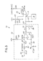
- the receiver includes a tone detection circuit 70, shown in circuit diagram form.
- the tone detection circuit 70 consists of an opamp crystal filter circuit 72 (with the same clock crystal as was used in the tone oscillator 20), and a peak detect and comparator circuit 74.
- a low-battery detector circuit is also provided and is shown in block diagram form in FIG. 10.
- the crystal filter circuit 72 receives demodulated voltage signals from a conventional FM receiver circuit (not shown) at point 78, where the signal passed through capacitor 80, clock crystal 82, capacitor 84 and into amplifier 88.
- a resistor 86 is placed between a 5 volt power supply and the positive input terminal of amp 88 for bias.
- Feedback resistor 90 is placed between the output of amp 88 and the negative terminal of amp 88.
- Resistor 92 and capacitor 94 are placed between the negative terminal and ground.
- the output of amp 96 is fed through a diode, to a low pass filter comprised of resistor 96 and capacitor 98.
- the peak detect/comparator circuit 74 receives the output signals from amplifier 88 on conductor 100, where they are fed past resistor 102. Resistor 102 sets the capacitor discharges time constant.
- the point A at the input terminal to comparator 106 is the point of interest for low battery detection, as discussed below. Resistors 108 and 110 provide a reference voltage at the positive terminal of comparator 106 as shown.
- the output signal of comparator 106 point B is low when the 32.768 KHZ is present (i.e., the transmitter's oscillator is active and the tones are detected in the circuit 72), and high when the tone is not present.
- This signal at B is input to the microphone receiver muting circuitry and controls the muting of conventional audio amplification and output circuits (not shown).
- Point A in FIG. 3 is essentially a DC voltage proportional to the amplitude of the tone signal from tone oscillator 20 (FIG. 1).
- the resistor 42 of FIG. 2 is switched out by transistor 44, as would be the case of a low battery indication from microcontroller 50, the change in amplitude in the tone from oscillator 20 can be detected at point A.
- the voltage from battery 12 (FIG. 1) supplies the tone oscillator 20 via DC amplifier 24, producing a gradual drop in the amplitude of the tone form the oscillator 20. This change in voltage can also be detected at point A.
- the negative terminal (conductor 100) of comparator 106 contains a dc voltage that is proportional to the amplitude level of the tone oscillator. This dc voltage then enters a buffer amplifier stage 41 through R1 and R2. R 1 and R2 are used to divide down the dc level, if desired ( i.e ., for flexibility).
- the buffer is used for isolation purposes; it looks like a high impedance, so it will not load down the signal at conductor 100.
- buffer amplifier 41 enters a commercially available analog to digital converter 42, for example, a Texas Instrument Device No. TLC549C.
- the dc level is converted to a digital signal.
- This digital signal is monitored by the ⁇ C which then updates the LCD display accordingly.
- the detection circuit 76 includes two sections of an LP339 comparator integrated circuit. This circuit 76 consists of resistors 110, 112, and 114 placed in series from a 12 V power supply, which set reference levels for comparison.
- the voltage signal at threshold T1 is supplied to the positive terminal of LP339 comparator 116.
- the voltage signal at threshold T2 is supplied to the negative terminal of comparator 118.
- the voltage signal from point A (Fig. 3) is supplied to the negative terminal of comparator 116, and the positive terminal of comparator 118.
- the comparator outputs are combined at point C, and are tied via a pull-up resistor 117 to +5 volts.
- Voltage threshold T1 is set such that when the battery 12 is sufficiently low, the tone's amplitude is reduced such that the voltage at point A falls below threshold T1, thus making the voltage at point C go high.
- This high signal at point C is fed to a suitable low battery indication circuit.
- a suitable low battery indication circuit Representative examples of such a circuit would be a microcontroller that operates an LED, or LCD display, or other visual or audible indicator, or a suitable alarm or warning circuit.
- a second threshold T2 is set such that when the amplitude of the tone at point A falls below T2 (indicating transmitter 10 is OFF), comparator 118 pulls to ground, sending a low signal at point C to the microcontroller, which tells the indication circuit to not activate the indicator.
- comparator 118 pulls to ground, sending a low signal at point C to the microcontroller, which tells the indication circuit to not activate the indicator.
- Many comparators could be used to detect more amplitude levels if greater resolution is desired.
- FIG. 5 shows the tone oscillator 20 circuit in the transmitter 10.
- the amplitude of the tone signal passed to the summing amplifier 34 may be varied by switching in and out the filter capacitor 120 in the buffer/filter portion 21 of the tone oscillator 20, as shown in FIG. 6.
- transistor 44 is switched on, causing tone level to drop at the input to the summing amp 34.
- An alternative circuit, shown in FIG. 7, has a resistor R in series with transistor 44, placed in parallel with capacitor 120.
- the switching of the voltage from tone oscillator 20 from high to low to indicate a low battery condition could be reversed with the voltage switching from low to high.
- the low battery detection circuit 76 would have to be modified to detect the increase in amplitude indicating a low battery condition.
Landscapes
- Physics & Mathematics (AREA)
- General Physics & Mathematics (AREA)
- Primary Cells (AREA)
- Transmitters (AREA)
- Tests Of Electric Status Of Batteries (AREA)
- Radar Systems Or Details Thereof (AREA)
- Selective Calling Equipment (AREA)
- Secondary Cells (AREA)
- Hybrid Cells (AREA)
Priority Applications (7)
| Application Number | Priority Date | Filing Date | Title |
|---|---|---|---|
| AT98306379T ATE243324T1 (de) | 1998-08-10 | 1998-08-10 | Gerät und verfahren zur anzeige der lebensdauer einer senderbatterie |
| DE69815675T DE69815675T2 (de) | 1998-08-10 | 1998-08-10 | Gerät und Verfahren zur Anzeige der Lebensdauer einer Senderbatterie |
| EP98306379A EP0980007B1 (en) | 1998-08-10 | 1998-08-10 | Transmitter battery life indication apparatus and method |
| ES98306379T ES2202753T3 (es) | 1998-08-10 | 1998-08-10 | Aparato y procedimiento de indicacion del estado de carga de la bateria de un transmisor. |
| PT98306379T PT980007E (pt) | 1998-08-10 | 1998-08-10 | Aparelho e metodo para indicar a vida da pilha de transmissor |
| DK98306379T DK0980007T3 (da) | 1998-08-10 | 1998-08-10 | Levetidsindikeringsapparat og -fremgangsmåde til transmitterbatteri |
| HK00105050.6A HK1028277B (en) | 2000-08-14 | Transmitter battery life indication apparatus and method |
Applications Claiming Priority (1)
| Application Number | Priority Date | Filing Date | Title |
|---|---|---|---|
| EP98306379A EP0980007B1 (en) | 1998-08-10 | 1998-08-10 | Transmitter battery life indication apparatus and method |
Publications (2)
| Publication Number | Publication Date |
|---|---|
| EP0980007A1 EP0980007A1 (en) | 2000-02-16 |
| EP0980007B1 true EP0980007B1 (en) | 2003-06-18 |
Family
ID=8234997
Family Applications (1)
| Application Number | Title | Priority Date | Filing Date |
|---|---|---|---|
| EP98306379A Expired - Lifetime EP0980007B1 (en) | 1998-08-10 | 1998-08-10 | Transmitter battery life indication apparatus and method |
Country Status (6)
| Country | Link |
|---|---|
| EP (1) | EP0980007B1 (da) |
| AT (1) | ATE243324T1 (da) |
| DE (1) | DE69815675T2 (da) |
| DK (1) | DK0980007T3 (da) |
| ES (1) | ES2202753T3 (da) |
| PT (1) | PT980007E (da) |
Families Citing this family (1)
| Publication number | Priority date | Publication date | Assignee | Title |
|---|---|---|---|---|
| JP2002281128A (ja) | 2001-03-16 | 2002-09-27 | Nec Corp | 携帯電話端末、その電池容量通知方法及びそのプログラム |
Family Cites Families (5)
| Publication number | Priority date | Publication date | Assignee | Title |
|---|---|---|---|---|
| US4484354A (en) * | 1980-10-16 | 1984-11-20 | Motorola, Inc. | Continuous tone decoder/encoder |
| JPS6064272A (ja) * | 1983-09-19 | 1985-04-12 | Nissan Motor Co Ltd | 無線式制御装置 |
| US4910795A (en) * | 1987-06-11 | 1990-03-20 | Mccowen Clinton R | Wireless hand held microphone |
| JPH04135398A (ja) * | 1990-09-27 | 1992-05-08 | Tamura Seisakusho Co Ltd | ワイヤレスマイクロフォンシステム |
| DE4340448C2 (de) * | 1993-11-27 | 1995-12-21 | Daimler Benz Ag | Ladevorratsanzeige für den Handsender eines fernbedienbaren Fahrzeug-Sicherungssystems |
-
1998
- 1998-08-10 ES ES98306379T patent/ES2202753T3/es not_active Expired - Lifetime
- 1998-08-10 DK DK98306379T patent/DK0980007T3/da active
- 1998-08-10 DE DE69815675T patent/DE69815675T2/de not_active Expired - Fee Related
- 1998-08-10 AT AT98306379T patent/ATE243324T1/de not_active IP Right Cessation
- 1998-08-10 PT PT98306379T patent/PT980007E/pt unknown
- 1998-08-10 EP EP98306379A patent/EP0980007B1/en not_active Expired - Lifetime
Also Published As
| Publication number | Publication date |
|---|---|
| ES2202753T3 (es) | 2004-04-01 |
| ATE243324T1 (de) | 2003-07-15 |
| DE69815675D1 (de) | 2003-07-24 |
| DK0980007T3 (da) | 2003-10-13 |
| HK1028277A1 (en) | 2001-02-09 |
| DE69815675T2 (de) | 2004-06-03 |
| PT980007E (pt) | 2003-11-28 |
| EP0980007A1 (en) | 2000-02-16 |
Similar Documents
| Publication | Publication Date | Title |
|---|---|---|
| US4785291A (en) | Distance monitor especially for child surveillance | |
| US5119072A (en) | Apparatus for monitoring child activity | |
| US5794125A (en) | Transmitter battery like indication apparatus and method | |
| US5708970A (en) | Wireless sound monitoring apparatus with subaudible squelch control | |
| US5563576A (en) | Vehicle security system siren with backup rechargeable battery | |
| EP0326129B1 (en) | Guiding device for visually handicapped person | |
| JP2609038B2 (ja) | 電池種類判別方法及び電池種類判別装置 | |
| US4633515A (en) | Emergency broadcast alert detector | |
| WO1987006748A1 (en) | Remote monitoring and alarm system | |
| JPH0676196A (ja) | 車輌の危険地域走行時注意放送の送、受信方法及びその装置 | |
| US5533959A (en) | Wireless remote monitors employing reassurance tones | |
| US6441599B1 (en) | Reference point locator for residential and commercial construction | |
| EP0980007B1 (en) | Transmitter battery life indication apparatus and method | |
| HK1028277B (en) | Transmitter battery life indication apparatus and method | |
| JP2000137551A (ja) | 端末装置 | |
| JP3279687B2 (ja) | ワイヤレス式ヘッドホン装置 | |
| US4328485A (en) | Binary alarm | |
| GB2311186A (en) | Hearing aid feedback detecting and warning device | |
| US20010026219A1 (en) | Battery having a lost article location module | |
| JPH11355081A (ja) | 鉄道等車両用の放送機構における騒音利得制御型の放送方法とその装置 | |
| KR200186343Y1 (ko) | 도난 경보 장치 | |
| KR100212574B1 (ko) | 차량 시동 검출 장치 | |
| JPH0693632B2 (ja) | 送信機 | |
| KR970005809B1 (ko) | 귀중품 보관용 가방 도난 방지 장치 | |
| JPS63496Y2 (da) |
Legal Events
| Date | Code | Title | Description |
|---|---|---|---|
| PUAI | Public reference made under article 153(3) epc to a published international application that has entered the european phase |
Free format text: ORIGINAL CODE: 0009012 |
|
| AK | Designated contracting states |
Kind code of ref document: A1 Designated state(s): AT BE CH CY DE DK ES FI FR GB GR IE IT LI LU MC NL PT SE |
|
| AX | Request for extension of the european patent |
Free format text: AL;LT;LV;MK;RO;SI |
|
| 17P | Request for examination filed |
Effective date: 20000810 |
|
| AKX | Designation fees paid |
Free format text: AT BE CH CY DE DK ES FI FR GB GR IE IT LI LU MC NL PT SE |
|
| 17Q | First examination report despatched |
Effective date: 20011010 |
|
| GRAH | Despatch of communication of intention to grant a patent |
Free format text: ORIGINAL CODE: EPIDOS IGRA |
|
| RAP1 | Party data changed (applicant data changed or rights of an application transferred) |
Owner name: SHURE INCORPORATED |
|
| GRAH | Despatch of communication of intention to grant a patent |
Free format text: ORIGINAL CODE: EPIDOS IGRA |
|
| GRAA | (expected) grant |
Free format text: ORIGINAL CODE: 0009210 |
|
| AK | Designated contracting states |
Designated state(s): AT BE CH CY DE DK ES FI FR GB GR IE IT LI LU MC NL PT SE |
|
| REG | Reference to a national code |
Ref country code: GB Ref legal event code: FG4D |
|
| REG | Reference to a national code |
Ref country code: CH Ref legal event code: EP |
|
| REG | Reference to a national code |
Ref country code: IE Ref legal event code: FG4D |
|
| REF | Corresponds to: |
Ref document number: 69815675 Country of ref document: DE Date of ref document: 20030724 Kind code of ref document: P |
|
| PG25 | Lapsed in a contracting state [announced via postgrant information from national office to epo] |
Ref country code: LU Free format text: LAPSE BECAUSE OF NON-PAYMENT OF DUE FEES Effective date: 20030810 Ref country code: CY Free format text: LAPSE BECAUSE OF FAILURE TO SUBMIT A TRANSLATION OF THE DESCRIPTION OR TO PAY THE FEE WITHIN THE PRESCRIBED TIME-LIMIT Effective date: 20030810 |
|
| REG | Reference to a national code |
Ref country code: SE Ref legal event code: TRGR |
|
| REG | Reference to a national code |
Ref country code: GR Ref legal event code: EP Ref document number: 20030403725 Country of ref document: GR |
|
| REG | Reference to a national code |
Ref country code: CH Ref legal event code: NV Representative=s name: JACOBACCI & PARTNERS S.P.A. |
|
| REG | Reference to a national code |
Ref country code: FR Ref legal event code: TP Ref country code: FR Ref legal event code: CL |
|
| REG | Reference to a national code |
Ref country code: PT Ref legal event code: TE4A Free format text: SHURE INCORP0RATED US Effective date: 20040205 Ref country code: PT Ref legal event code: PC4A Free format text: SHURE ACQUISITION HOLDINGS, INC. US Effective date: 20040205 |
|
| REG | Reference to a national code |
Ref country code: ES Ref legal event code: FG2A Ref document number: 2202753 Country of ref document: ES Kind code of ref document: T3 |
|
| REG | Reference to a national code |
Ref country code: GB Ref legal event code: 732E |
|
| REG | Reference to a national code |
Ref country code: GB Ref legal event code: 732E |
|
| ET | Fr: translation filed | ||
| PLBE | No opposition filed within time limit |
Free format text: ORIGINAL CODE: 0009261 |
|
| STAA | Information on the status of an ep patent application or granted ep patent |
Free format text: STATUS: NO OPPOSITION FILED WITHIN TIME LIMIT |
|
| RAP2 | Party data changed (patent owner data changed or rights of a patent transferred) |
Owner name: SHURE ACQUISITION HOLDINGS, INC. |
|
| REG | Reference to a national code |
Ref country code: PT Ref legal event code: QB4A Free format text: SHURE INCORPORATED US Effective date: 20040205 |
|
| 26N | No opposition filed |
Effective date: 20040319 |
|
| NLT2 | Nl: modifications (of names), taken from the european patent patent bulletin |
Owner name: SHURE ACQUISITION HOLDINGS, INC. |
|
| PGFP | Annual fee paid to national office [announced via postgrant information from national office to epo] |
Ref country code: MC Payment date: 20040728 Year of fee payment: 7 |
|
| PGFP | Annual fee paid to national office [announced via postgrant information from national office to epo] |
Ref country code: PT Payment date: 20040729 Year of fee payment: 7 |
|
| PGFP | Annual fee paid to national office [announced via postgrant information from national office to epo] |
Ref country code: NL Payment date: 20040803 Year of fee payment: 7 |
|
| PGFP | Annual fee paid to national office [announced via postgrant information from national office to epo] |
Ref country code: GB Payment date: 20040804 Year of fee payment: 7 |
|
| PGFP | Annual fee paid to national office [announced via postgrant information from national office to epo] |
Ref country code: SE Payment date: 20040806 Year of fee payment: 7 |
|
| PGFP | Annual fee paid to national office [announced via postgrant information from national office to epo] |
Ref country code: FR Payment date: 20040810 Year of fee payment: 7 |
|
| PGFP | Annual fee paid to national office [announced via postgrant information from national office to epo] |
Ref country code: IE Payment date: 20040811 Year of fee payment: 7 Ref country code: AT Payment date: 20040811 Year of fee payment: 7 |
|
| PGFP | Annual fee paid to national office [announced via postgrant information from national office to epo] |
Ref country code: FI Payment date: 20040812 Year of fee payment: 7 |
|
| PGFP | Annual fee paid to national office [announced via postgrant information from national office to epo] |
Ref country code: DK Payment date: 20040813 Year of fee payment: 7 |
|
| PGFP | Annual fee paid to national office [announced via postgrant information from national office to epo] |
Ref country code: CH Payment date: 20040818 Year of fee payment: 7 |
|
| PGFP | Annual fee paid to national office [announced via postgrant information from national office to epo] |
Ref country code: DE Payment date: 20040819 Year of fee payment: 7 |
|
| PGFP | Annual fee paid to national office [announced via postgrant information from national office to epo] |
Ref country code: ES Payment date: 20040825 Year of fee payment: 7 |
|
| PGFP | Annual fee paid to national office [announced via postgrant information from national office to epo] |
Ref country code: GR Payment date: 20040827 Year of fee payment: 7 |
|
| PGFP | Annual fee paid to national office [announced via postgrant information from national office to epo] |
Ref country code: BE Payment date: 20041021 Year of fee payment: 7 |
|
| PG25 | Lapsed in a contracting state [announced via postgrant information from national office to epo] |
Ref country code: IT Free format text: LAPSE BECAUSE OF NON-PAYMENT OF DUE FEES;WARNING: LAPSES OF ITALIAN PATENTS WITH EFFECTIVE DATE BEFORE 2007 MAY HAVE OCCURRED AT ANY TIME BEFORE 2007. THE CORRECT EFFECTIVE DATE MAY BE DIFFERENT FROM THE ONE RECORDED. Effective date: 20050810 Ref country code: IE Free format text: LAPSE BECAUSE OF NON-PAYMENT OF DUE FEES Effective date: 20050810 Ref country code: GB Free format text: LAPSE BECAUSE OF NON-PAYMENT OF DUE FEES Effective date: 20050810 Ref country code: FI Free format text: LAPSE BECAUSE OF NON-PAYMENT OF DUE FEES Effective date: 20050810 Ref country code: AT Free format text: LAPSE BECAUSE OF NON-PAYMENT OF DUE FEES Effective date: 20050810 |
|
| PG25 | Lapsed in a contracting state [announced via postgrant information from national office to epo] |
Ref country code: SE Free format text: LAPSE BECAUSE OF NON-PAYMENT OF DUE FEES Effective date: 20050811 Ref country code: ES Free format text: LAPSE BECAUSE OF NON-PAYMENT OF DUE FEES Effective date: 20050811 |
|
| PG25 | Lapsed in a contracting state [announced via postgrant information from national office to epo] |
Ref country code: MC Free format text: LAPSE BECAUSE OF NON-PAYMENT OF DUE FEES Effective date: 20050831 Ref country code: LI Free format text: LAPSE BECAUSE OF NON-PAYMENT OF DUE FEES Effective date: 20050831 Ref country code: DK Free format text: LAPSE BECAUSE OF NON-PAYMENT OF DUE FEES Effective date: 20050831 Ref country code: CH Free format text: LAPSE BECAUSE OF NON-PAYMENT OF DUE FEES Effective date: 20050831 Ref country code: BE Free format text: LAPSE BECAUSE OF NON-PAYMENT OF DUE FEES Effective date: 20050831 |
|
| PG25 | Lapsed in a contracting state [announced via postgrant information from national office to epo] |
Ref country code: PT Free format text: LAPSE BECAUSE OF NON-PAYMENT OF DUE FEES Effective date: 20060210 |
|
| PG25 | Lapsed in a contracting state [announced via postgrant information from national office to epo] |
Ref country code: NL Free format text: LAPSE BECAUSE OF NON-PAYMENT OF DUE FEES Effective date: 20060301 Ref country code: DE Free format text: LAPSE BECAUSE OF NON-PAYMENT OF DUE FEES Effective date: 20060301 |
|
| PG25 | Lapsed in a contracting state [announced via postgrant information from national office to epo] |
Ref country code: GR Free format text: LAPSE BECAUSE OF NON-PAYMENT OF DUE FEES Effective date: 20060302 |
|
| REG | Reference to a national code |
Ref country code: CH Ref legal event code: PL |
|
| REG | Reference to a national code |
Ref country code: DK Ref legal event code: EBP |
|
| EUG | Se: european patent has lapsed | ||
| GBPC | Gb: european patent ceased through non-payment of renewal fee |
Effective date: 20050810 |
|
| PG25 | Lapsed in a contracting state [announced via postgrant information from national office to epo] |
Ref country code: FR Free format text: LAPSE BECAUSE OF NON-PAYMENT OF DUE FEES Effective date: 20060428 |
|
| NLV4 | Nl: lapsed or anulled due to non-payment of the annual fee |
Effective date: 20060301 |
|
| REG | Reference to a national code |
Ref country code: IE Ref legal event code: MM4A |
|
| REG | Reference to a national code |
Ref country code: FR Ref legal event code: ST Effective date: 20060428 |
|
| REG | Reference to a national code |
Ref country code: ES Ref legal event code: FD2A Effective date: 20050811 |
|
| BERE | Be: lapsed |
Owner name: *SHURE INC. Effective date: 20050831 |