EP0979721B1 - Dispositif et procédé pour le moulage par injection-étirage-soufflage - Google Patents
Dispositif et procédé pour le moulage par injection-étirage-soufflage Download PDFInfo
- Publication number
- EP0979721B1 EP0979721B1 EP99122703A EP99122703A EP0979721B1 EP 0979721 B1 EP0979721 B1 EP 0979721B1 EP 99122703 A EP99122703 A EP 99122703A EP 99122703 A EP99122703 A EP 99122703A EP 0979721 B1 EP0979721 B1 EP 0979721B1
- Authority
- EP
- European Patent Office
- Prior art keywords
- preforms
- preform
- injection
- blow molding
- pitch
- Prior art date
- Legal status (The legal status is an assumption and is not a legal conclusion. Google has not performed a legal analysis and makes no representation as to the accuracy of the status listed.)
- Expired - Lifetime
Links
- 238000010103 injection stretch blow moulding Methods 0.000 title claims description 46
- 238000000034 method Methods 0.000 title claims description 31
- 210000003739 neck Anatomy 0.000 claims description 236
- 238000000071 blow moulding Methods 0.000 claims description 213
- 230000007246 mechanism Effects 0.000 claims description 206
- 239000007924 injection Substances 0.000 claims description 187
- 238000002347 injection Methods 0.000 claims description 186
- 238000000465 moulding Methods 0.000 claims description 117
- 238000001746 injection moulding Methods 0.000 claims description 103
- 238000010438 heat treatment Methods 0.000 claims description 81
- 238000012546 transfer Methods 0.000 claims description 62
- 238000001816 cooling Methods 0.000 claims description 37
- 230000008859 change Effects 0.000 claims description 15
- 229920000139 polyethylene terephthalate Polymers 0.000 claims description 8
- 230000008569 process Effects 0.000 claims description 3
- 238000009826 distribution Methods 0.000 description 17
- 239000005020 polyethylene terephthalate Substances 0.000 description 7
- 230000002829 reductive effect Effects 0.000 description 7
- 238000006243 chemical reaction Methods 0.000 description 6
- 238000002425 crystallisation Methods 0.000 description 6
- 230000008025 crystallization Effects 0.000 description 6
- 238000005520 cutting process Methods 0.000 description 6
- 239000000047 product Substances 0.000 description 6
- 230000001105 regulatory effect Effects 0.000 description 6
- 238000010276 construction Methods 0.000 description 5
- 239000002826 coolant Substances 0.000 description 4
- 238000009434 installation Methods 0.000 description 4
- 229920005989 resin Polymers 0.000 description 4
- 239000011347 resin Substances 0.000 description 4
- 238000000926 separation method Methods 0.000 description 4
- 229920003002 synthetic resin Polymers 0.000 description 4
- 239000000057 synthetic resin Substances 0.000 description 4
- 238000007599 discharging Methods 0.000 description 3
- 238000003780 insertion Methods 0.000 description 3
- 230000037431 insertion Effects 0.000 description 3
- -1 polyethylene terephthalate Polymers 0.000 description 3
- 238000007664 blowing Methods 0.000 description 2
- 230000003750 conditioning effect Effects 0.000 description 2
- 230000008602 contraction Effects 0.000 description 2
- 238000010586 diagram Methods 0.000 description 2
- 238000002474 experimental method Methods 0.000 description 2
- 239000012467 final product Substances 0.000 description 2
- 230000002452 interceptive effect Effects 0.000 description 2
- 238000004519 manufacturing process Methods 0.000 description 2
- 239000000463 material Substances 0.000 description 2
- 238000003303 reheating Methods 0.000 description 2
- 230000002441 reversible effect Effects 0.000 description 2
- 230000007723 transport mechanism Effects 0.000 description 2
- XLYOFNOQVPJJNP-UHFFFAOYSA-N water Substances O XLYOFNOQVPJJNP-UHFFFAOYSA-N 0.000 description 2
- 230000005856 abnormality Effects 0.000 description 1
- 230000006978 adaptation Effects 0.000 description 1
- 230000002411 adverse Effects 0.000 description 1
- 230000008901 benefit Effects 0.000 description 1
- 239000000969 carrier Substances 0.000 description 1
- 239000000498 cooling water Substances 0.000 description 1
- 230000007547 defect Effects 0.000 description 1
- 230000001419 dependent effect Effects 0.000 description 1
- 238000013461 design Methods 0.000 description 1
- 230000000694 effects Effects 0.000 description 1
- 239000012530 fluid Substances 0.000 description 1
- 238000010102 injection blow moulding Methods 0.000 description 1
- 239000011810 insulating material Substances 0.000 description 1
- 238000009413 insulation Methods 0.000 description 1
- 238000012986 modification Methods 0.000 description 1
- 230000004048 modification Effects 0.000 description 1
- 239000002991 molded plastic Substances 0.000 description 1
- 239000012778 molding material Substances 0.000 description 1
- 230000036961 partial effect Effects 0.000 description 1
- 238000002360 preparation method Methods 0.000 description 1
- 230000009467 reduction Effects 0.000 description 1
- 230000008439 repair process Effects 0.000 description 1
- 238000011160 research Methods 0.000 description 1
- 230000000717 retained effect Effects 0.000 description 1
- 239000002699 waste material Substances 0.000 description 1
- 230000002087 whitening effect Effects 0.000 description 1
Images


Classifications
-
- B—PERFORMING OPERATIONS; TRANSPORTING
- B29—WORKING OF PLASTICS; WORKING OF SUBSTANCES IN A PLASTIC STATE IN GENERAL
- B29C—SHAPING OR JOINING OF PLASTICS; SHAPING OF MATERIAL IN A PLASTIC STATE, NOT OTHERWISE PROVIDED FOR; AFTER-TREATMENT OF THE SHAPED PRODUCTS, e.g. REPAIRING
- B29C49/00—Blow-moulding, i.e. blowing a preform or parison to a desired shape within a mould; Apparatus therefor
- B29C49/28—Blow-moulding apparatus
-
- B—PERFORMING OPERATIONS; TRANSPORTING
- B29—WORKING OF PLASTICS; WORKING OF SUBSTANCES IN A PLASTIC STATE IN GENERAL
- B29C—SHAPING OR JOINING OF PLASTICS; SHAPING OF MATERIAL IN A PLASTIC STATE, NOT OTHERWISE PROVIDED FOR; AFTER-TREATMENT OF THE SHAPED PRODUCTS, e.g. REPAIRING
- B29C49/00—Blow-moulding, i.e. blowing a preform or parison to a desired shape within a mould; Apparatus therefor
- B29C49/02—Combined blow-moulding and manufacture of the preform or the parison
- B29C49/06—Injection blow-moulding
-
- B—PERFORMING OPERATIONS; TRANSPORTING
- B29—WORKING OF PLASTICS; WORKING OF SUBSTANCES IN A PLASTIC STATE IN GENERAL
- B29C—SHAPING OR JOINING OF PLASTICS; SHAPING OF MATERIAL IN A PLASTIC STATE, NOT OTHERWISE PROVIDED FOR; AFTER-TREATMENT OF THE SHAPED PRODUCTS, e.g. REPAIRING
- B29C49/00—Blow-moulding, i.e. blowing a preform or parison to a desired shape within a mould; Apparatus therefor
- B29C49/42—Component parts, details or accessories; Auxiliary operations
- B29C49/4205—Handling means, e.g. transfer, loading or discharging means
- B29C49/42113—Means for manipulating the objects' position or orientation
- B29C49/42121—Changing the center-center distance
- B29C49/42122—Adapting to blow-mould cavity center-center distance
-
- B—PERFORMING OPERATIONS; TRANSPORTING
- B29—WORKING OF PLASTICS; WORKING OF SUBSTANCES IN A PLASTIC STATE IN GENERAL
- B29C—SHAPING OR JOINING OF PLASTICS; SHAPING OF MATERIAL IN A PLASTIC STATE, NOT OTHERWISE PROVIDED FOR; AFTER-TREATMENT OF THE SHAPED PRODUCTS, e.g. REPAIRING
- B29C49/00—Blow-moulding, i.e. blowing a preform or parison to a desired shape within a mould; Apparatus therefor
- B29C49/42—Component parts, details or accessories; Auxiliary operations
- B29C49/48—Moulds
-
- B—PERFORMING OPERATIONS; TRANSPORTING
- B29—WORKING OF PLASTICS; WORKING OF SUBSTANCES IN A PLASTIC STATE IN GENERAL
- B29C—SHAPING OR JOINING OF PLASTICS; SHAPING OF MATERIAL IN A PLASTIC STATE, NOT OTHERWISE PROVIDED FOR; AFTER-TREATMENT OF THE SHAPED PRODUCTS, e.g. REPAIRING
- B29C49/00—Blow-moulding, i.e. blowing a preform or parison to a desired shape within a mould; Apparatus therefor
- B29C49/42—Component parts, details or accessories; Auxiliary operations
- B29C49/64—Heating or cooling preforms, parisons or blown articles
- B29C49/6409—Thermal conditioning of preforms
- B29C49/6418—Heating of preforms
-
- B—PERFORMING OPERATIONS; TRANSPORTING
- B29—WORKING OF PLASTICS; WORKING OF SUBSTANCES IN A PLASTIC STATE IN GENERAL
- B29C—SHAPING OR JOINING OF PLASTICS; SHAPING OF MATERIAL IN A PLASTIC STATE, NOT OTHERWISE PROVIDED FOR; AFTER-TREATMENT OF THE SHAPED PRODUCTS, e.g. REPAIRING
- B29C49/00—Blow-moulding, i.e. blowing a preform or parison to a desired shape within a mould; Apparatus therefor
- B29C49/42—Component parts, details or accessories; Auxiliary operations
- B29C49/64—Heating or cooling preforms, parisons or blown articles
- B29C49/6409—Thermal conditioning of preforms
- B29C49/6427—Cooling of preforms
-
- B—PERFORMING OPERATIONS; TRANSPORTING
- B29—WORKING OF PLASTICS; WORKING OF SUBSTANCES IN A PLASTIC STATE IN GENERAL
- B29C—SHAPING OR JOINING OF PLASTICS; SHAPING OF MATERIAL IN A PLASTIC STATE, NOT OTHERWISE PROVIDED FOR; AFTER-TREATMENT OF THE SHAPED PRODUCTS, e.g. REPAIRING
- B29C49/00—Blow-moulding, i.e. blowing a preform or parison to a desired shape within a mould; Apparatus therefor
- B29C49/42—Component parts, details or accessories; Auxiliary operations
- B29C49/64—Heating or cooling preforms, parisons or blown articles
- B29C49/6409—Thermal conditioning of preforms
- B29C49/6436—Thermal conditioning of preforms characterised by temperature differential
- B29C49/6445—Thermal conditioning of preforms characterised by temperature differential through the preform length
-
- B—PERFORMING OPERATIONS; TRANSPORTING
- B29—WORKING OF PLASTICS; WORKING OF SUBSTANCES IN A PLASTIC STATE IN GENERAL
- B29C—SHAPING OR JOINING OF PLASTICS; SHAPING OF MATERIAL IN A PLASTIC STATE, NOT OTHERWISE PROVIDED FOR; AFTER-TREATMENT OF THE SHAPED PRODUCTS, e.g. REPAIRING
- B29C49/00—Blow-moulding, i.e. blowing a preform or parison to a desired shape within a mould; Apparatus therefor
- B29C49/42—Component parts, details or accessories; Auxiliary operations
- B29C49/64—Heating or cooling preforms, parisons or blown articles
- B29C49/6409—Thermal conditioning of preforms
- B29C49/6463—Thermal conditioning of preforms by contact heating or cooling, e.g. mandrels or cores specially adapted for heating or cooling preforms
-
- B—PERFORMING OPERATIONS; TRANSPORTING
- B29—WORKING OF PLASTICS; WORKING OF SUBSTANCES IN A PLASTIC STATE IN GENERAL
- B29C—SHAPING OR JOINING OF PLASTICS; SHAPING OF MATERIAL IN A PLASTIC STATE, NOT OTHERWISE PROVIDED FOR; AFTER-TREATMENT OF THE SHAPED PRODUCTS, e.g. REPAIRING
- B29C35/00—Heating, cooling or curing, e.g. crosslinking or vulcanising; Apparatus therefor
- B29C35/02—Heating or curing, e.g. crosslinking or vulcanizing during moulding, e.g. in a mould
- B29C35/08—Heating or curing, e.g. crosslinking or vulcanizing during moulding, e.g. in a mould by wave energy or particle radiation
- B29C35/0805—Heating or curing, e.g. crosslinking or vulcanizing during moulding, e.g. in a mould by wave energy or particle radiation using electromagnetic radiation
- B29C2035/0822—Heating or curing, e.g. crosslinking or vulcanizing during moulding, e.g. in a mould by wave energy or particle radiation using electromagnetic radiation using IR radiation
-
- B—PERFORMING OPERATIONS; TRANSPORTING
- B29—WORKING OF PLASTICS; WORKING OF SUBSTANCES IN A PLASTIC STATE IN GENERAL
- B29C—SHAPING OR JOINING OF PLASTICS; SHAPING OF MATERIAL IN A PLASTIC STATE, NOT OTHERWISE PROVIDED FOR; AFTER-TREATMENT OF THE SHAPED PRODUCTS, e.g. REPAIRING
- B29C49/00—Blow-moulding, i.e. blowing a preform or parison to a desired shape within a mould; Apparatus therefor
- B29C49/02—Combined blow-moulding and manufacture of the preform or the parison
- B29C2049/023—Combined blow-moulding and manufacture of the preform or the parison using inherent heat of the preform, i.e. 1 step blow moulding
-
- B—PERFORMING OPERATIONS; TRANSPORTING
- B29—WORKING OF PLASTICS; WORKING OF SUBSTANCES IN A PLASTIC STATE IN GENERAL
- B29C—SHAPING OR JOINING OF PLASTICS; SHAPING OF MATERIAL IN A PLASTIC STATE, NOT OTHERWISE PROVIDED FOR; AFTER-TREATMENT OF THE SHAPED PRODUCTS, e.g. REPAIRING
- B29C49/00—Blow-moulding, i.e. blowing a preform or parison to a desired shape within a mould; Apparatus therefor
- B29C49/42—Component parts, details or accessories; Auxiliary operations
- B29C49/48—Moulds
- B29C2049/4879—Moulds characterised by mould configurations
- B29C2049/4882—Mould cavity geometry
-
- B—PERFORMING OPERATIONS; TRANSPORTING
- B29—WORKING OF PLASTICS; WORKING OF SUBSTANCES IN A PLASTIC STATE IN GENERAL
- B29C—SHAPING OR JOINING OF PLASTICS; SHAPING OF MATERIAL IN A PLASTIC STATE, NOT OTHERWISE PROVIDED FOR; AFTER-TREATMENT OF THE SHAPED PRODUCTS, e.g. REPAIRING
- B29C2949/00—Indexing scheme relating to blow-moulding
- B29C2949/07—Preforms or parisons characterised by their configuration
- B29C2949/081—Specified dimensions, e.g. values or ranges
- B29C2949/0811—Wall thickness
- B29C2949/0817—Wall thickness of the body
-
- B—PERFORMING OPERATIONS; TRANSPORTING
- B29—WORKING OF PLASTICS; WORKING OF SUBSTANCES IN A PLASTIC STATE IN GENERAL
- B29C—SHAPING OR JOINING OF PLASTICS; SHAPING OF MATERIAL IN A PLASTIC STATE, NOT OTHERWISE PROVIDED FOR; AFTER-TREATMENT OF THE SHAPED PRODUCTS, e.g. REPAIRING
- B29C2949/00—Indexing scheme relating to blow-moulding
- B29C2949/07—Preforms or parisons characterised by their configuration
- B29C2949/081—Specified dimensions, e.g. values or ranges
- B29C2949/0829—Height, length
- B29C2949/0835—Height, length of the body
-
- B—PERFORMING OPERATIONS; TRANSPORTING
- B29—WORKING OF PLASTICS; WORKING OF SUBSTANCES IN A PLASTIC STATE IN GENERAL
- B29C—SHAPING OR JOINING OF PLASTICS; SHAPING OF MATERIAL IN A PLASTIC STATE, NOT OTHERWISE PROVIDED FOR; AFTER-TREATMENT OF THE SHAPED PRODUCTS, e.g. REPAIRING
- B29C2949/00—Indexing scheme relating to blow-moulding
- B29C2949/20—Preforms or parisons whereby a specific part is made of only one component, e.g. only one layer
- B29C2949/22—Preforms or parisons whereby a specific part is made of only one component, e.g. only one layer at neck portion
-
- B—PERFORMING OPERATIONS; TRANSPORTING
- B29—WORKING OF PLASTICS; WORKING OF SUBSTANCES IN A PLASTIC STATE IN GENERAL
- B29C—SHAPING OR JOINING OF PLASTICS; SHAPING OF MATERIAL IN A PLASTIC STATE, NOT OTHERWISE PROVIDED FOR; AFTER-TREATMENT OF THE SHAPED PRODUCTS, e.g. REPAIRING
- B29C2949/00—Indexing scheme relating to blow-moulding
- B29C2949/20—Preforms or parisons whereby a specific part is made of only one component, e.g. only one layer
- B29C2949/24—Preforms or parisons whereby a specific part is made of only one component, e.g. only one layer at flange portion
-
- B—PERFORMING OPERATIONS; TRANSPORTING
- B29—WORKING OF PLASTICS; WORKING OF SUBSTANCES IN A PLASTIC STATE IN GENERAL
- B29C—SHAPING OR JOINING OF PLASTICS; SHAPING OF MATERIAL IN A PLASTIC STATE, NOT OTHERWISE PROVIDED FOR; AFTER-TREATMENT OF THE SHAPED PRODUCTS, e.g. REPAIRING
- B29C2949/00—Indexing scheme relating to blow-moulding
- B29C2949/20—Preforms or parisons whereby a specific part is made of only one component, e.g. only one layer
- B29C2949/26—Preforms or parisons whereby a specific part is made of only one component, e.g. only one layer at body portion
-
- B—PERFORMING OPERATIONS; TRANSPORTING
- B29—WORKING OF PLASTICS; WORKING OF SUBSTANCES IN A PLASTIC STATE IN GENERAL
- B29C—SHAPING OR JOINING OF PLASTICS; SHAPING OF MATERIAL IN A PLASTIC STATE, NOT OTHERWISE PROVIDED FOR; AFTER-TREATMENT OF THE SHAPED PRODUCTS, e.g. REPAIRING
- B29C2949/00—Indexing scheme relating to blow-moulding
- B29C2949/20—Preforms or parisons whereby a specific part is made of only one component, e.g. only one layer
- B29C2949/28—Preforms or parisons whereby a specific part is made of only one component, e.g. only one layer at bottom portion
-
- B—PERFORMING OPERATIONS; TRANSPORTING
- B29—WORKING OF PLASTICS; WORKING OF SUBSTANCES IN A PLASTIC STATE IN GENERAL
- B29C—SHAPING OR JOINING OF PLASTICS; SHAPING OF MATERIAL IN A PLASTIC STATE, NOT OTHERWISE PROVIDED FOR; AFTER-TREATMENT OF THE SHAPED PRODUCTS, e.g. REPAIRING
- B29C2949/00—Indexing scheme relating to blow-moulding
- B29C2949/30—Preforms or parisons made of several components
- B29C2949/3024—Preforms or parisons made of several components characterised by the number of components or by the manufacturing technique
-
- B—PERFORMING OPERATIONS; TRANSPORTING
- B29—WORKING OF PLASTICS; WORKING OF SUBSTANCES IN A PLASTIC STATE IN GENERAL
- B29C—SHAPING OR JOINING OF PLASTICS; SHAPING OF MATERIAL IN A PLASTIC STATE, NOT OTHERWISE PROVIDED FOR; AFTER-TREATMENT OF THE SHAPED PRODUCTS, e.g. REPAIRING
- B29C2949/00—Indexing scheme relating to blow-moulding
- B29C2949/30—Preforms or parisons made of several components
- B29C2949/3032—Preforms or parisons made of several components having components being injected
-
- B—PERFORMING OPERATIONS; TRANSPORTING
- B29—WORKING OF PLASTICS; WORKING OF SUBSTANCES IN A PLASTIC STATE IN GENERAL
- B29C—SHAPING OR JOINING OF PLASTICS; SHAPING OF MATERIAL IN A PLASTIC STATE, NOT OTHERWISE PROVIDED FOR; AFTER-TREATMENT OF THE SHAPED PRODUCTS, e.g. REPAIRING
- B29C35/00—Heating, cooling or curing, e.g. crosslinking or vulcanising; Apparatus therefor
- B29C35/02—Heating or curing, e.g. crosslinking or vulcanizing during moulding, e.g. in a mould
-
- B—PERFORMING OPERATIONS; TRANSPORTING
- B29—WORKING OF PLASTICS; WORKING OF SUBSTANCES IN A PLASTIC STATE IN GENERAL
- B29C—SHAPING OR JOINING OF PLASTICS; SHAPING OF MATERIAL IN A PLASTIC STATE, NOT OTHERWISE PROVIDED FOR; AFTER-TREATMENT OF THE SHAPED PRODUCTS, e.g. REPAIRING
- B29C35/00—Heating, cooling or curing, e.g. crosslinking or vulcanising; Apparatus therefor
- B29C35/16—Cooling
-
- B—PERFORMING OPERATIONS; TRANSPORTING
- B29—WORKING OF PLASTICS; WORKING OF SUBSTANCES IN A PLASTIC STATE IN GENERAL
- B29C—SHAPING OR JOINING OF PLASTICS; SHAPING OF MATERIAL IN A PLASTIC STATE, NOT OTHERWISE PROVIDED FOR; AFTER-TREATMENT OF THE SHAPED PRODUCTS, e.g. REPAIRING
- B29C49/00—Blow-moulding, i.e. blowing a preform or parison to a desired shape within a mould; Apparatus therefor
- B29C49/42—Component parts, details or accessories; Auxiliary operations
- B29C49/4205—Handling means, e.g. transfer, loading or discharging means
- B29C49/42073—Grippers
- B29C49/42075—Grippers with pivoting clamps
-
- B—PERFORMING OPERATIONS; TRANSPORTING
- B29—WORKING OF PLASTICS; WORKING OF SUBSTANCES IN A PLASTIC STATE IN GENERAL
- B29C—SHAPING OR JOINING OF PLASTICS; SHAPING OF MATERIAL IN A PLASTIC STATE, NOT OTHERWISE PROVIDED FOR; AFTER-TREATMENT OF THE SHAPED PRODUCTS, e.g. REPAIRING
- B29C49/00—Blow-moulding, i.e. blowing a preform or parison to a desired shape within a mould; Apparatus therefor
- B29C49/42—Component parts, details or accessories; Auxiliary operations
- B29C49/4205—Handling means, e.g. transfer, loading or discharging means
- B29C49/42093—Transporting apparatus, e.g. slides, wheels or conveyors
- B29C49/42105—Transporting apparatus, e.g. slides, wheels or conveyors for discontinuous or batch transport
-
- B—PERFORMING OPERATIONS; TRANSPORTING
- B29—WORKING OF PLASTICS; WORKING OF SUBSTANCES IN A PLASTIC STATE IN GENERAL
- B29C—SHAPING OR JOINING OF PLASTICS; SHAPING OF MATERIAL IN A PLASTIC STATE, NOT OTHERWISE PROVIDED FOR; AFTER-TREATMENT OF THE SHAPED PRODUCTS, e.g. REPAIRING
- B29C49/00—Blow-moulding, i.e. blowing a preform or parison to a desired shape within a mould; Apparatus therefor
- B29C49/42—Component parts, details or accessories; Auxiliary operations
- B29C49/42378—Handling malfunction
- B29C49/4238—Ejecting defective preforms or products
-
- B—PERFORMING OPERATIONS; TRANSPORTING
- B29—WORKING OF PLASTICS; WORKING OF SUBSTANCES IN A PLASTIC STATE IN GENERAL
- B29C—SHAPING OR JOINING OF PLASTICS; SHAPING OF MATERIAL IN A PLASTIC STATE, NOT OTHERWISE PROVIDED FOR; AFTER-TREATMENT OF THE SHAPED PRODUCTS, e.g. REPAIRING
- B29C49/00—Blow-moulding, i.e. blowing a preform or parison to a desired shape within a mould; Apparatus therefor
- B29C49/42—Component parts, details or accessories; Auxiliary operations
- B29C49/64—Heating or cooling preforms, parisons or blown articles
- B29C49/6409—Thermal conditioning of preforms
- B29C49/6436—Thermal conditioning of preforms characterised by temperature differential
- B29C49/6458—Thermal conditioning of preforms characterised by temperature differential tangentially, i.e. along circumference
-
- B—PERFORMING OPERATIONS; TRANSPORTING
- B29—WORKING OF PLASTICS; WORKING OF SUBSTANCES IN A PLASTIC STATE IN GENERAL
- B29C—SHAPING OR JOINING OF PLASTICS; SHAPING OF MATERIAL IN A PLASTIC STATE, NOT OTHERWISE PROVIDED FOR; AFTER-TREATMENT OF THE SHAPED PRODUCTS, e.g. REPAIRING
- B29C49/00—Blow-moulding, i.e. blowing a preform or parison to a desired shape within a mould; Apparatus therefor
- B29C49/42—Component parts, details or accessories; Auxiliary operations
- B29C49/64—Heating or cooling preforms, parisons or blown articles
- B29C49/6409—Thermal conditioning of preforms
- B29C49/6436—Thermal conditioning of preforms characterised by temperature differential
- B29C49/6462—Thermal conditioning of preforms characterised by temperature differential by masking
-
- B—PERFORMING OPERATIONS; TRANSPORTING
- B29—WORKING OF PLASTICS; WORKING OF SUBSTANCES IN A PLASTIC STATE IN GENERAL
- B29C—SHAPING OR JOINING OF PLASTICS; SHAPING OF MATERIAL IN A PLASTIC STATE, NOT OTHERWISE PROVIDED FOR; AFTER-TREATMENT OF THE SHAPED PRODUCTS, e.g. REPAIRING
- B29C49/00—Blow-moulding, i.e. blowing a preform or parison to a desired shape within a mould; Apparatus therefor
- B29C49/42—Component parts, details or accessories; Auxiliary operations
- B29C49/64—Heating or cooling preforms, parisons or blown articles
- B29C49/6409—Thermal conditioning of preforms
- B29C49/6463—Thermal conditioning of preforms by contact heating or cooling, e.g. mandrels or cores specially adapted for heating or cooling preforms
- B29C49/6465—Cooling
-
- B—PERFORMING OPERATIONS; TRANSPORTING
- B29—WORKING OF PLASTICS; WORKING OF SUBSTANCES IN A PLASTIC STATE IN GENERAL
- B29C—SHAPING OR JOINING OF PLASTICS; SHAPING OF MATERIAL IN A PLASTIC STATE, NOT OTHERWISE PROVIDED FOR; AFTER-TREATMENT OF THE SHAPED PRODUCTS, e.g. REPAIRING
- B29C49/00—Blow-moulding, i.e. blowing a preform or parison to a desired shape within a mould; Apparatus therefor
- B29C49/42—Component parts, details or accessories; Auxiliary operations
- B29C49/64—Heating or cooling preforms, parisons or blown articles
- B29C49/6409—Thermal conditioning of preforms
- B29C49/6463—Thermal conditioning of preforms by contact heating or cooling, e.g. mandrels or cores specially adapted for heating or cooling preforms
- B29C49/6467—Thermal conditioning of preforms by contact heating or cooling, e.g. mandrels or cores specially adapted for heating or cooling preforms on the outside
-
- B—PERFORMING OPERATIONS; TRANSPORTING
- B29—WORKING OF PLASTICS; WORKING OF SUBSTANCES IN A PLASTIC STATE IN GENERAL
- B29C—SHAPING OR JOINING OF PLASTICS; SHAPING OF MATERIAL IN A PLASTIC STATE, NOT OTHERWISE PROVIDED FOR; AFTER-TREATMENT OF THE SHAPED PRODUCTS, e.g. REPAIRING
- B29C49/00—Blow-moulding, i.e. blowing a preform or parison to a desired shape within a mould; Apparatus therefor
- B29C49/42—Component parts, details or accessories; Auxiliary operations
- B29C49/64—Heating or cooling preforms, parisons or blown articles
- B29C49/68—Ovens specially adapted for heating preforms or parisons
- B29C49/6835—Ovens specially adapted for heating preforms or parisons using reflectors
-
- B—PERFORMING OPERATIONS; TRANSPORTING
- B29—WORKING OF PLASTICS; WORKING OF SUBSTANCES IN A PLASTIC STATE IN GENERAL
- B29C—SHAPING OR JOINING OF PLASTICS; SHAPING OF MATERIAL IN A PLASTIC STATE, NOT OTHERWISE PROVIDED FOR; AFTER-TREATMENT OF THE SHAPED PRODUCTS, e.g. REPAIRING
- B29C49/00—Blow-moulding, i.e. blowing a preform or parison to a desired shape within a mould; Apparatus therefor
- B29C49/42—Component parts, details or accessories; Auxiliary operations
- B29C49/64—Heating or cooling preforms, parisons or blown articles
- B29C49/68—Ovens specially adapted for heating preforms or parisons
- B29C49/685—Rotating the preform in relation to heating means
-
- B—PERFORMING OPERATIONS; TRANSPORTING
- B29—WORKING OF PLASTICS; WORKING OF SUBSTANCES IN A PLASTIC STATE IN GENERAL
- B29K—INDEXING SCHEME ASSOCIATED WITH SUBCLASSES B29B, B29C OR B29D, RELATING TO MOULDING MATERIALS OR TO MATERIALS FOR MOULDS, REINFORCEMENTS, FILLERS OR PREFORMED PARTS, e.g. INSERTS
- B29K2067/00—Use of polyesters or derivatives thereof, as moulding material
-
- B—PERFORMING OPERATIONS; TRANSPORTING
- B29—WORKING OF PLASTICS; WORKING OF SUBSTANCES IN A PLASTIC STATE IN GENERAL
- B29K—INDEXING SCHEME ASSOCIATED WITH SUBCLASSES B29B, B29C OR B29D, RELATING TO MOULDING MATERIALS OR TO MATERIALS FOR MOULDS, REINFORCEMENTS, FILLERS OR PREFORMED PARTS, e.g. INSERTS
- B29K2105/00—Condition, form or state of moulded material or of the material to be shaped
- B29K2105/25—Solid
- B29K2105/253—Preform
Definitions
- This invention relates to an injection stretch blow molding apparatus according to the preamble of claim 1 and a method according to the preamble of claim 21.
- Methods for blow molding a container from a preform include that known as the cold parison or 2-stage method and that which is known as the hot parison or 1-stage method.
- the preforms required for the blow molding at least an injection cavity mold which shapes the outer wall of the preform and an injection core mold which shapes the inner wall of the preform are necessary. Also, after the injection cavity mold and the injection core mold are clamped together and the preform is injection molded, with the molds still clamped together it is necessary to cool the preform down to a temperature at which the preform can be released from the molds.
- the blow molding cycle time is not affected by the injection molding cycle time.
- the cold parison method involves reheating preforms which have been cooled to room temperature the cold parison method is inferior to the hot parison method in its energy efficiency.
- cycle time of the overall apparatus is determined by the injection molding cycle time, which of all the cycles is the one requiring the most time. Consequently there has been the problem that when the time required for injection molding is long, the throughput of the whole apparatus is low.
- the preform is mold-released at a higher temperature than in the cold parison method, there is a limit on this mold-release temperature and consequently it is not possible to greatly speed up the injection molding cycle.
- One reason for this is that when the preform mold-release temperature is high, when the injection core mold is released from the preform, a moldrelease called lifting, wherein the preform sticks to the core mold, occurs. Also, after the injection core mold is released from the preform, because there is no longer any member restricting deformation of the preform, deformation caused by temperature nonuniformity and thermal contraction and the like make it impossible for preforms conforming to the design to be ejected. Furthermore, when the cooling effected by the injection core mold is inadequate, crystallization caused by inadequate cooling occurs, particularly at the inner wall of the preform, and a preform of which the trunk portion is opaque is ejected.
- the blow cavity mold is the most expensive, and the cost of this blow cavity mold increases roughly in proportion to the number of cavities in it. Even if a mold is expensive, if its operation rate is high then it can be used cost-effectively; however, because as described above the cycle time of the overall apparatus. depends on the injection molding cycle time and cannot be shortened, the operation rate of each cavity in the blow cavity mold has unavoidably been low. Also, when the number of bottles blow molded simultaneously increases, not only the number of cavities in the blow mold but also the number of drawing rods and blow core molds and mechanisms for supporting and driving these increases, and this has resulted in increases in the size and cost of the apparatus.
- an injection stretch blow molding apparatus and method of the related art are known.
- Such an apparatus comprises a preform molding station in which simultaneously N preforms are injection molded and a blow molding station with a circulatory carrier for intermittently carrying and blow molding n ⁇ N preforms to containers.
- This apparatus allows an economic adaptation of a larger injection molding cycle to the shorter blow molding cycle.
- a predetermined array of injection molded preforms is transported from the preform molding station to the blow molding station. From this array of injection molded preforms pairs of preforms are separated by means of the circulatory carrier in the blow molding station, wherein the pitch between the preforms is kept constant.
- Document GB-A-2 093 396 discloses an apparatus and a method for injection blow molding containers.
- This known apparatus comprises a preform molding station and a blow molding station. Between the preform molding station and the blow molding station there are arranged a first rotatable platen and a second rotatable platen.
- the first rotatable platen serves as a first transfer mechanism for receiving preforms from the preform molding station and for transferring the preforms to the second rotatable platen.
- the preforms carried by the second rotatable platen are then transferred by a separate transportion mechanism to a blow mold. In this blow mold rows of preforms are separated, while the pitch between the preforms in one row is kept constant.
- This apparatus comprises a preform molding station with a first circulatory carrier and a blow molding station with a second circulatory carrier. Between the two circulatory carriers an intermittent mechanism is arranged by means of which the preforms are transferred from the first circulatory carrier of the preform molding station to the second circulatory carrier of the blow molding station while having the same pitch between the preforms.
- This apparatus is not part of the related art, since the number of injection molded preforms is equal to the number of containers to be blow molded.
- Document FR-A-2 389 580 discloses an apparatus and a method for blow molding containers.
- This known apparatus comprises a preform molding section and a blow molding section Between the two molding sections a transfer mechanism is arranged which has several holding members by means of which a predetermined number of preforms is carried from the preform molding section to the blow molding section.
- the number of preforms injection molded in one cycle is equal to the number of containers blow molded in the same cycle.
- the holding members are moveable with respect to each other so that the pitch between the preforms can be changed.
- Document EP-A-0 534 367 discloses an apparatus for conditioning pressure molded plastic articles.
- This apparatus comprises a pressure molding machine and a blow molding machine. Between the two machines a linear transport mechanism is arranged by means of which a predetermined number of preforms is transported from the pressure molding machine to the blow molding machine through a temperature conditioning station. During the handling of the preforms from the pressure molding machine to the transport mechanism the pitch between the preforms is changed.
- a bottle production apparatus which comprises a preform molding section and a blow molding section.
- a blow molding station with a circulatory carrier for intermittently carrying the preforms is not disclosed.
- Adjacent to the preform molding station a transfer mechanism is arranged by means of which preforms produced by the preform molding station are transported to a plate.
- a second transfer mechanism By means of a second transfer mechanism the preforms arranged on the plate are transported to the blow molding section wherein the pitch between the preforms is adjusted to the distance between the blow molds.
- the number n of preforms simultaneously blow molded is made smaller than the number N of preforms simultaneously injection molded, fewer cavities are required in the blow mold and mold costs, molds being consumable items, can be greatly reduced. Also, because fewer blow core molds, stretching rods, and mechanisms for supporting and driving these are required, the apparatus can be made more compact and cheaper. Furthermore, because N simultaneously molded preforms are blow molded n (n ⁇ N) at a time over a plurality of blow molding cycles within the shortened injection molding cycle time, the operating rate of the n cavities in the blow cavity mold increases.
- a heating section for heating the preforms being carried to the blow molding section can be provided.
- the preforms can be brought to a temperature suitable for blow molding by cooling performed by the injection molds and reheating of the cooled preforms, and the temperature stability from cycle to cycle therefore increases. Since the preforms have their heat holdings, they can attain a temperature suitable for blow molding merely by adding a certain heat to the preforms in many cases. Therefore, the preforms require a relatively short time period to heat them. Further, containers of the desired wall thickness can be obtained by providing a longitudinal distribution of temperature to the preforms in the heating step. Also, even though N simultaneously injection molded preforms are blow molded n preforms at a time over (N/n) blow molding cycles, control reducing the temperature variation among blow molding cycles can easily be carried out.
- a second circulatory carrier comprises a plurality of carrier members which remain spaced at equal intervals along the second carrying path, and each of the carrier members has a supporting portion for supporting a preform in an inverted or an upright state. It is preferable that the array pitch at which the plurality of carrier members are spaced along the second carrier path be made equal to the array pitch P of the plurality of cavities in the blow cavity mold. This is because it makes pitch-conversion in the carrying process unnecessary. When this is done, the array pitch of the preforms in the heating section of the invention is greater than the small pitch at which the preforms are arrayed in the heating section in a conventional 2-stage system.
- the heating time can be short and the length of the heating section does not have to be made long as it does in the cold parison case.
- a step of allowing the preforms to cool between the separation of the preforms from the injection core mold and the start of the blow molding step, over a period of time long enough for the temperature difference between the inner and outer walls of the preforms to be moderated can be provided.
- the method of this invention because the period of time for which the preforms are cooled by the injection core mold in contact with their inner walls is made longer than conventionally, a relatively steep temperature gradient forms between the inner and outer walls of the preforms, and the temperature in the outer wall vicinity becomes greater than that in the inner wall vicinity.
- n (n ⁇ 2) containers simultaneously be blow molded from n preforms using n blow cavities arrayed at a blow molding pitch P, that the preforms being carried along the second carrying path be carried with the array pitch of the carrier members kept equal to this pitch P, and that in the preform transferring step a process wherein n preforms are simultaneously transferred to n carrier members is repeated a plurality of times.
- an injection stretch blow molding apparatus comprises:
- an injection stretch blow molding method wherein injection molded preforms are transferred from a preform molding station to a blow molding station by way of a transfer station and the preforms are blow molded into containers in the blow molding station is characterized in that:
- the preforms are molded in an upright state with their neck portions facing upward.
- the injection mold clamping is vertical clamping and is therefore space-saving.
- resin is normally injected from the preform bottom portion side
- a stable arrangement wherein the injecting apparatus and the injection cavity mold are disposed on a machine bed and the injection core mold is disposed thereabove can be employed.
- the openings at their neck portions can be used to have the preforms support themselves easily.
- the drawing.rods and blow core molds consequently have to be positioned underneath the preforms, they can be disposed using a space in the machine bed and the overall height of the blow molding section can be made low.
- a preform can be inverted while the other preform is being received.
- the system of the present invention can easily be applied to a more rapid cycle of molding.
- the pitch of injection molding in the preform molding station is larger than the pitch of blow molding in the blow molding station. It is thus preferable that the receiving mechanism includes a pitch changing-mechanism for changing said preforms from the injection molding pitch to the blow molding pitch.
- the blow molding pitch can be attained immediately after the receiving mechanism has received the preforms.
- the system of the present invention can easily be applied to any molding apparatus which requires the change of pitch.
- the preform has its barrel diameter smaller than that of its final product configuration. Thus, the number of preforms to be handled can be increased. The optimum pitch can be provided in the blow molding stage.
- the inverting mechanism may include a pitch changing mechanism for changing said preforms from the injection molding pitch to the blow molding pitch.
- the inverting mechanism can perform its inverting step while changing the preforms from the injection molding pitch to the blow molding pitch immediately after the receiving mechanism has received the preforms.
- the system of the present invention can easily be applied to any molding apparatus which requires the change of pitch.
- Such a change of pitch may be carried out in the transfer station between the preform molding station and the blow molding station.
- the transfer station changes the array pitch of the preforms from the injection molding pitch to the blow molding pitch immediately after the transfer station has received the preforms from the preform molding station and thereafter inverts the preforms.
- each of said preforms has a flange portion having a diameter that is larger than the external diameter of the barrel below the neck.
- the receiving mechanism may include holding members each of which engages the bottom of the flange portion to hold the preform.
- the flange portion can reliably hold the preform as through a support ring or the like and yet will 1 not damage the preform since the flange does not almost contact the barrel or other part of the preform.
- Each of the holding members may include an open/close mechanism for holding and releasing the preform.
- the open/close mechanism may include a passage portion which can hold the flange portion of the preform while permitting the barrel portion smaller than the flange portion to pass through the passage portion.
- the open/close mechanism of the holding member can reliably hold the preform without any play and yet be opened to release the preform easily and positively when the preform is to be removed.
- Each of the holding members of the receiving mechanism may include a holding part which contacts at least part of the bottom and barrel of the preform to hold the preform.
- the bottom or barrel of the preform can be reliably held by the holding part irrespectively of the final product configuration.
- Each of the holding members of the receiving mechanism may have means for cooling the outer wall of the preform.
- the cooling means can cool the preform while being held by the holding member.
- the outer wall of the preform has its temperature higher than that of the inner wall thereof since the outer wall is not in contact with other parts such as core pins or the like.
- the circulatory carrier may be adapted to orientate carrier members at the preform receiving position opposed to the inverting mechanism, the number of said carrier members being equal to the number N of preforms which have been injection molded simultaneously in the preform molding station.
- the inverting mechanism may have a holding mechanism for holding the N preforms at the same time.
- a holding mechanism can simultaneously deliver the N preforms to the same number (N) of said carrier members stopped at the preform receiving position while inverting the preforms.
- the blow molded articles can be delivered to the carrier member at a batch manner.
- the delivery of preforms can be once attained to simplify the system in procedure and construction.
- the apparatus may further include a device for moving the receiving mechanism in the horizontal direction.
- the receiving mechanism will be horizontally moved by such a device after it has received the preforms at a position just below the removal section of the injection molding station.
- the preforms can be delivered to the inverting mechanism.
- the delivery of preforms from the receiving mechanism to the inverting mechanism can be more simply performed using a more simplified mechanism for moving the receiving mechanism in the horizontal direction.
- the apparatus may include a further device for moving the inverting mechanism in the horizontal direction.
- the inverting mechanism will be horizontally moved by the further device after the inverting mechanism has received the preforms from the receiving mechanism.
- the preforms will be delivered to the N carrier members.
- the inverting mechanism is positioned at its stand-by place until all the carrier members have been moved to the preform receiving position, while holding the preforms in their inverted state with the neck parts being directed downwardly.
- the preforms can be delivered to the carrier members with less behavior and/or time immediately after all the carrier member have been moved to the preform receiving position.
- an injection stretch blow molding method comprises the steps of:
- the preform injection molding step can form a preform having the maximum wall thickness ranging between 3.0 mm and 4.0 mm. If the wall thickness of the preform is larger than the maximum value, the difference of temperature between the inner and outer walls of the preform becomes too large. This undesirably requires increase of time required to reduce the difference of temperature or any special means for heating the inner wall of the preform.
- N/n is an integer when the injection and blow molding steps are repeated.
- N/n is an integer
- the N preforms simultaneously injection molded in a first cycle are all used over an integral number (N/n) of blow molding cycles n at a time, and none of these preforms are mixed with and simultaneously blow molded with any of the N preforms simultaneously molded in the subsequent second cycle. If preforms from different injection molding cycles are mixed and blow molded together, the carrying sequence is different from the case wherein preforms molded in the same injection molding cycle are simultaneously blow molded together, and the control and structure of the apparatus become complicated; however, this invention eliminates this problem.
- a blow molding apparatus comprises:
- the receiving, heating, blow molding and outlet sections are disposed on the respective sides of the circulatory carrier forming the substantially rectangular carrying path in the direction of article conveyance, all the sides of the carrying path can effectively be utilized to perform a cycle of molding.
- the inside area of the circulatory carrier can effectively be used as a space wherein the clamping mechanism of the blow molding apparatus is moved for clamping. As a result, the effective space can be further saved, resulting in provision of a compact system.
- a blow molding apparatus wherein preforms carried in an inverted state with neck portions thereof facing downward or in an upright state with the neck portions facing upward are heated in a heating section before being carried to a blow molding section is characterized in that:
- the region below the neck portion when the preform is upright is the nearest to the cavity surface of the blow cavity mold, it is a region which is to be draw orientated relatively much.
- it can be heated to a higher temperature than the trunk portion region heated by the first heaters disposed on one side only, and a high drawing orientation degree can be secured.
- the first heaters are disposed on one side only, the arrangement is saving.
- the efficiency with which the region below the neck is heated increases, there is the benefit that the heating time can be shortened and the overall length of the heating section can be made short.
- a blow molding apparatus wherein preforms are intermittently carried to a blow molding section via a heating section is characterized in that:
- the temperature distributions in the synthetic resin preforms which have poor thermal conductivity, can be moderated. Normally, because heating in the heating section is carried out from around the preforms, the inner wall temperature of the preforms becomes lower than the outer wall temperature.
- the preforms can be given a temperature distribution for blow molding which could not be obtained just by simply heating the preforms while rotating them.
- the temperature regulating member may be in the form of a temperature regulating core that is inserted into the interior of the preform to regulate the temperature of the inner preform wall.
- the temperature regulating member may be in the form of a temperature regulating pot that has a cylindrical portion disposed around the preform.
- the temperature regulating pot can divide the preform into axial zones each of which is independently controlled in temperature.
- One or more of such temperature regulating members may extend along the axial direction of the preform at one or more points around the periphery of the preform. This can provide a distribution of different temperatures in the circumferential direction of the preform.
- Another injection stretch blow molding apparatus comprising a preform molding section for molding preforms and a blow molding section for blow molding containers from the preforms retaining heat from when the preforms were injection molded is characterized in that:
- the injection stretch blow molding apparatus may include a machine base on which the preform molding and blow molding sections are mounted.
- the discharge guide section may include a preform falling port formed through the top face of the machine base and a chute for conducting the preform from the falling port to the machine base side.
- Another injection stretch blow molding method wherein preforms are injection molded in a preform molding section and these preforms are carried to a blow molding section and containers are blow molded from the preforms retaining heat from when the preforms were injection molded comprises the steps of:
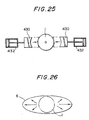
- FIGs. 1 through 26 One embodiment of the present invention is shown in Figs. 1 through 26.
- Figs. 1 through 26 show an injection stretch blow molding apparatus which is one embodiment of the present invention.
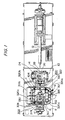
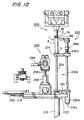
- Fig. 1, Fig. 2 and Fig. 3 respectively are a plan view, a front view and a left side view of the apparatus of this preferred embodiment
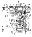
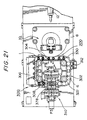
- Fig. 4 is an enlarged view showing the main parts of the apparatus of the preferred embodiment.
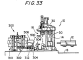
- the apparatus comprises a preform molding station 10, a transfer station 200 and a blow molding station 300 disposed on a machine bed 8.
- the preform molding station 10 has a rotary disc 30 which has an injection core mold 50 in each of two locations an angle of rotation 180° apart and is a first circulatory carrier which circulatorily carries the injection core molds 50 intermittently along a rotary carrying path.
- An injection molding section 14 facing an injecting apparatus 12 and a preform ejecting section 16 facing this injection molding section 14 are respectively provided at the stopping positions of the injection core molds 50.
- the injection core mold 50 is released from the preforms 1.
- a neck portion of each preform 1 is molded by means of a neck cavity mold 60 which will be further discussed later, and the preforms 1 are held by this neck cavity mold 60 and the injection core mold 50 and carried by the rotary disc 30 to the preform ejecting section 16.
- the preforms 1 are ejected by being released from the neck cavity mold 60 after a partial release of the injection core mold 50.
- the blow molding station 300 has a second circulatory carrier 302 comprising four sprockets 320a to 320d and a carrier chain 322 running around these sprockets.
- a plurality of for example ten carrier members 330 are fixed to this carrier chain 322 uniformly spaced apart, and a preform 1 or a bottle 6 is supported by each carrier member 330.
- a preform receiving section 304 which receives the preforms 1 from the transfer station 200
- a heating section 306 which heats the preforms 1
- a standby section 308 which causes the heated preforms 1 to temporarily standby
- a blow molding section 310 which blow molds the preforms 1 into bottles 6, and a bottle ejecting section 312 which ejects the bottles 6 to outside the apparatus.
- the transfer station 200 transfers the preforms 1 ejected from the preform ejecting section 16 of the preform molding station 10 to the preform receiving section 304 of the blow molding station 300.
- preforms 1 i.e. the number of preforms 1 simultaneously molded in the injection molding section 14
- n preforms 1 i.e. the number of preforms 1 simultaneously molded in the blow molding section 310 of the blow molding station 300
- four preforms 1 simultaneously ejected by the preform ejecting section 16 are transferred one at a time to the preform receiving section 304.
- the preforms 1 are injection molded in an upright state
- the transfer station 200 the preforms 1 are turned upside-down and transferred to the blow molding station 300 in an inverted state.
- the injection. molding section 14 of the preform molding station 10 is provided with a lower clamping plate 20 mounted on the machine bed 8.
- a for example circular upper clamping plate 22 is disposed above this lower mold clamping plate 20 and extends from the injection molding section 14 into the preform ejecting section 16.
- This upper mold clamping plate 22 is movable vertically along four tie bars 24 provided in four locations around the injection molding section 14.
- a fixed plate 26 is mounted on the upper ends of the tie bars 24 and a clamping cylinder 28 is mounted on this fixed plate 26.
- the clamping cylinder 28 drives a clamping rod 28a (see Fig. 4), and the upper clamping plate 22 is driven up and down by this clamping rod 28a.
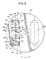
- the rotary disc 30 constituting the first circulatory carrier is rotatably mounted at the underside of the upper clamping plate 22. As shown in Fig. 7, this rotary disc 30 is fixed to a rotational shaft 34 rotationally driven by a rotary actuator 32 fixed to the upper clamping plate 22. As shown in Fig. 5, which is an underside view of the rotary disc 30, the two injection core molds 50 and the two neck cavity molds 60 are mounted on the rotary disc 30 in positions corresponding to the injection molding section 14 and the preform ejecting section 16. The details of the injection core molds 50 and the neck cavity molds 60 will be discussed in detail later.
- the injection molding section 14 is provided with a hot runner mold 40 with which a nozzle of the injecting apparatus 12 nozzle-touches, and the injection cavity mold 42 is mounted on this hot runner mold 40.
- This injection cavity mold 42 has a cavity for each of the N preforms 1 simultaneously molded in the injection molding section 14, for example four cavities.
- This injection cavity mold 42 is capable of cooling the injection molded preforms, and a coolant, for example water at room temperature, is circulated therethrough.
- the two injection core molds 50 mounted on the rotary disc 30 each have the same number of core pins 52 as the number N of preforms simultaneously molded, for example four core pins 52.
- the base portions 52a of these core pins 52 are supported by a core presser plate 54 fixed to the underside of the rotary disc 30 and a core fixing plate 56 fixed to the underside of this core presser plate 54.
- the two neck cavity molds 60 mounted on the rotary disc 30 are made up of pairs of split molds 62a and 62b, each neck cavity mold 60 comprising the same number of pairs of split molds 62a and 62b as the number N of preforms simultaneously molded, for example four.
- the pairs of split molds 62a and 62b of each neck cavity mold 60 are fixed by split plates 64a and 64b, and these split plates 64a and 64b constitute a neck fixing plate 64.
- a neck presser plate 65 which pushes this neck fixing plate 64 downward is disposed on the upper surface side of the split plates 64a and 64b.
- guide plates 66 which support the undersides of the ends of the neck fixing plate 64.
- the split plates 64a and 64b are kept normally closed by springs 64c shown in Fig. 5.
- a wedge hole 64d is provided at each end of the split plates 64a and 64b.
- a vertical lifting and lowering pin 70 has its lower end fixed in the guide plate 66, and a flange 70a is formed at the upper end of this lifting and lowering pin 70.
- a guide cylinder 72 extends downward from the underside of the rotary disc 30, and the lifting and lowering pin 70 is disposed inside this guide cylinder 72.
- a return spring 74 is disposed between the inner wall of the bottom portion of the guide cylinder 72 and the flange 70a of the lifting and lowering pin 70. The upward urging force of these return springs 74 urges the guide plate 66 upward at all times, and as a result the neck presser plate 65 is normally in contact with the underside of the core fixing plate 56.
- the injection core mold 50 and the neck cavity mold 60 are kept clamped together.
- an external force (which will be further discussed later) is applied to the lifting and lowering pins 70, the lifting and lowering pins 70 descend against the urging force of the return springs 74 and the neck presser plate 65 is driven down so that it moves away from the underside of the core fixing plate 56 and pushes the neck fixing plate 64 downward.
- the core pins 52 of the injection core mold 50 are released from the preforms 1 whose neck portions 2 are held by the neck cavity mold 60.
- the preform ejection drive mechanism is made up of a neck mold-release driver 80 and a split mold opening driver 100.
- the neck mold-release driver 80 has a first cylinder 82, and this first cylinder 82 is mounted on a first cylinder mounting plate 84b supported on the upper clamping plate 22 by way of first support rods 84a.
- the first cylinder 82 drives a first raising and lowering plate 86 up and down by way of a first piston rod 82a.
- Presser drive rods 88 are provided at each end of this first raising and lowering plate 86.
- Holes 22a are provided in the upper clamping plate 22 passing through from the upper surface to the lower surface thereof, and the presser drive rods 88 are disposed in these holes 22a.
- the initial position of the first raising and lowering plate 86 is a position such that the ends of the presser drive rods 88 do not project below the underside of the upper clamping plate 22 so they do not obstruct the rotation of the rotary disc 30.
- the rotary disc 30, the core presser plate 54 and the core fixing plate 56 respectively have holes 30a, 54a and 56a in positions facing the holes 22a in the upper clamping plate 22.
- Driven rods 68 disposed in the holes 30a, 54a and 56a are mounted on the upper surface of the neck presser plate 65.
- the neck presser plate 65 and the neck fixing plate 64 are driven down against the urging force of the return springs 74 by the first cylinder 82 by way of the first piston rod 82a, the presser drive rods 88 and the driven rods 68.
- this causes the core pins 52 of the injection core mold 50 to release from the preforms 1 whose neck portions 2 are held by the neck cavity mold 60.
- the core pins 52 of the injection core mold 50 do not have to be pulled completely clear of the open ends of the preforms 1, it only being necessary that at least gaps through which air can enter form between the core pins 52 and the inner walls of the preforms 1.
- the downward stroke of the neck fixing plate 64 that is the releasing stroke of the core pins 52 (the length L shown in Fig. 10), is set at for example 50mm.
- this split mold opening driver 100 has for example two second cylinders 102.
- These second cylinders 102 are mounted on a second cylinder mounting plate 104b supported on the first raising and lowering plate 86 by way of second support rods 104a.
- the first raising and lowering plate 86 is driven up or down by the first cylinder 82
- the second cylinders 102 are also moved up or down at the same time.
- These second cylinders 102 drive second raising and lowering plates 106 up and down by way of second piston rods 102a.
- the split plate opening cams 108 are mounted on these second raising and lowering plates 106.
- the lower end portions of these split plate opening cams 108 are of a wedge shape fitting the wedge holes 64d formed in the split plates 64a and 64b constituting the neck fixing plate 64.
- the split plate opening cams 108 are driven down and the wedge portions at their ends are thereby inserted into the wedge holes 64d in the neck fixing plate 64, and this opens the split plates 64a and 64b. Consequently the pairs of split molds 62a and 62b mounted on this pair of split plates 64a and 64b are opened, and the preforms 1 are ejected from the neck cavity mold 60.
- the drive timing of the second cylinders 102 is set to after the first cylinder 82 is driven.
- the clamping cylinder 28 is driven and the upper clamping plate 22 is thereby driven down, whereby the injection core mold 50 and the neck cavity mold 60 are clamped to the injection cavity mold 42.
- the preforms 1 injection molding material for example polyethylene terephthalate (PET)
- PET polyethylene terephthalate
- the injection cavity mold 42, the injection core mold 50 and the neck cavity mold 60 each have a coolant, for example water at room temperature, circulating through them, and the resin injected into the cavity bounded by the molds can be immediately cooled.
- a coolant for example water at room temperature
- the injection core mold 50 and the neck cavity mold 60 can be lifted up away from the injection cavity mold 42 as shown by the mold-open state of Fig. 10.
- the neck portions 2 of the preforms 1 form an undercut with respect to the mold-release direction, the injection molded preforms 1 are held on the injection core mold 50 and neck cavity mold 60 side and are released from the injection cavity mold 42.
- the timing at which this mold-release starts in the injection molding section 14 can be made considerably earlier than a conventional mold-release starting timing.
- the cooling time of the preforms 1 in the injection molding section 14 can be shortened. This is because even after the preforms 1 have been released from the injection cavity mold 42 the core pins 52 of the injection core mold 50 remain inside the preforms 1 and deformation of the preforms 1 accompanying their thermal contraction can be prevented. Therefore, the mold-release temperature of the preforms 1 in the injection molding section 14 only has to be low enough for a skin layer thick enough for the shape of the preforms 1 to be maintained after they are released from the injection cavity mold 42 to form at the outer surfaces of the preforms 1, and can be higher than conventional mold-release temperatures.
- the clamped state of the injection core mold 50 and the neck cavity mold 60 with respect to the preforms 1 released from the injection cavity mold 42 is maintained by the core fixing plate 56 and the neck presser plate 65 being kept in contact with each other by the return springs 74.
- This clamped state of the injection core mold 50 and the neck cavity mold 60 is maintained through the subsequent preforms 1 carrying step and until in the preform ejecting section 16 the injection core mold 50 is released from the preforms 1. Cooling of the preforms 1 is possible throughout the time during which this clamped state of the injection core mold 50 and the neck cavity mold 60 is maintained.
- the preforms 1 are carried from the injection molding section 14 to the preform ejecting section 16 by the rotary actuator 32 being driven and the rotary disc 30 constituting the first circulatory carrier being rotated thereby through 180°. During this preforms 1 carrying step, it is possible for cooling of the preforms 1 by the coolant circulating through the injection core mold 50 and the neck cavity mold 60 to continue without interruption.
- the inner wall side is more liable to be inadequately cooled than the outer wall because the heat-radiating surface area at the inner wall side of the preform 1 is smaller than at the outer wall side and furthermore heat is confined in the interior of the preform 1.
- the preforms 1 are mold-released at a relatively high temperature, in the subsequent carrying step it is possible for the preforms 1 to continue to be cooled by the injection core mold 50 and the neck cavity mold 60.
- the inner walls of the preforms 1 can be uninterruptedly cooled by the core pins 52 of the injection core mold 50; crystallization and loss of transparency caused by inadequate cooling can be certainly prevented.
- the neck portions 2, which because they are thick have large heat capacities and are more liable to crystallize than other portions, can be cooled by the neck cavity mold 60 and prevented from crystallizing.
- the preforms 1 can be cooled as they were during the above-mentioned carrying step. At this time, even if in the injection molding section 14 the clamping cylinder 28 has been driven and the upper clamping plate 22 lowered for the injection molding of the next preforms, because the above-mentioned clamped state in the preform ejecting section 16 is maintained, cooling of the preforms 1 can be continued.
- Cooling of the preforms 1 by the core pins 52 of the injection core mold 50 only has to continue long enough for crystallization caused by inadequate cooling of the inner walls of the preforms 1 to be prevented and for deformation of the ejected preforms 1 to be avoided, and indeed if the preforms 1 are excessively cooled by the core pins 52, removal of the core pins 52 becomes difficult. Therefore, in this preform ejecting section 16, first the injection core mold 50 is released from the preforms 1. In this preferred embodiment, this is achieved by the neck cavity mold 60 holding the preforms 1 being released from the injection core mold 50.
- This separation of the neck cavity mold 60 is carried out by the neck presser plate 65 kept in contact with the core fixing plate 56 by the urging force of the return springs 74 being lowered by the neck mold-release driver 80.
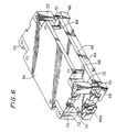
- the first cylinder 82 of the neck mold-release driver 80 is driven, the pushing force thereof transmitted through the first piston rod 82a, the first raising and lowering plate 86, the presser drive rods 88 and the driven rods 68 causes the neck fixing plate 64 to be pressed against the neck presser plate 65 and be driven downward as shown in Fig. 6 and Fig. 10.
- the preforms 1 have their neck portions 2 held by the neck cavity mold 60, the preforms 1 are also driven downward together with the neck fixing plate 64 and the neck cavity mold 60. Consequently, the separation of the neck cavity mold 60 from the injection core mold 50 results in the injection core mold 50 being released from the preforms 1.
- This mold-releasing stroke of the injection core mold 50 with respect to the preforms 1 does not have to be so long that the core pins 52 are pulled completely clear of the open ends of the preforms 1 for the subsequent carrying of the preforms 1 as it does conventionally, and need only be long enough for at least gaps through which air can enter to be formed between the inner walls of the preforms 1 and the core pins 52. Consequently, the mold-releasing stroke of the injection core mold 50 depends on the angle of the removal taper provided on the core pins 52 and the inner walls of the preforms 1, and the greater this removal taper angle is, the shorter the mold-release stroke need be. Because the mold-releasing stroke of the injection core mold 50 can be shortened in this way the installation height of the first cylinder 82 can be made low and the overall height of the injection molding apparatus can be made low, and this is advantageous in the transportation and installation of the apparatus.
- the preforms 1 have their neck portions 2 held by the neck cavity mold 60 comprising the pairs of split molds 62a and 62b, the preforms 1 can be ejected by this neck cavity mold 60 being released.
- the second cylinders 102 of the split mold opening driver 100 are driven. This driving force of the second cylinders 102 is transmitted to the split plate opening cams 108 by way of the second piston rods 102a and the second raising and lowering plates 106.
- the split plate opening cams 108 being driven downward, as shown in Fig.
- the second cylinders 102 which drive these split plate opening cams 108 are mounted on the first raising and lowering plate 86, driven by the first cylinder 82 and because before the split plate opening cams 108 are driven the first raising and lowering plate 86 is driven, the actual downward stroke through which the split plate opening cams 108 are driven by the second cylinders 102 is short.
- the installation height of the second cylinders 102 can be made low, the overall height of the injection molding apparatus an be made low, and an apparatus advantageous from the points of view of transportation and installation can be provided.
- the first and second cylinders 82 and 102 return to their original states.
- the neck presser plate 65 is. brought back into contact with the core fixing plate 56 by the return springs 74, and the injection core mold 50 and the neck cavity mold 60 are returned to their clamped state in preparation for the next injection molding.
- the cooling and mold-releasing steps described above carried out in the preform ejecting section 16 only have to be finished within the time taken for the injection molding of the next, new preforms in the injection molding section 14 to finish, in other words within the injection molding cycle time.
- the preform 1 cooling time depends particularly on the thickness of the trunk portions of the preforms 1, and the thicker the preforms 1 are the longer the cooling time that must be provided.
- this cooling time can be,adjusted by way of the setting of the timing of the mold-release of the injection core mold 50 in the preform ejecting section 16 as well as by adjusting the cooling time in the injection molding section 14.
- a highly flexible preform injection molding station can be provided.
- the injection core molds 50 and the neck cavity molds 60 in the two sections 14 and 16 are changed around by the rotary disc 30 being rotated through 180° by the rotary actuator 32.
- the rotary actuator 32 consists of reversible rotary carrying means of which the rotary carrying direction reverses each time.
- the preforms 1 are given a uniform temperature or a suitable temperature distribution, it is possible to mold bottles of a desired thickness. Also, because whitening crystallization of the bottles is prevented, highly transparent bottles can be molded.
- This invention is not limited to being applied to the hot parison blow molding described above, and of course can also be applied to so-called cold parison blow molding wherein the preforms are returned to room temperature before being heated again and blow molded. In this case also, there is the effect that the injection molding cycle time can be shortened.
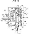
- Fig. 12 to Fig. 15 show a mechanism corresponding not to the preferred embodiment apparatus shown in Fig. 1 but rather corresponding to a preferred embodiment apparatus shown in Fig. 21.
- This transfer station 200 has a receiving and lowering mechanism 210 which receives and lowers preforms 1 ejected from the preform ejecting section 16 of the preform molding station 10, and an inverting and handing over mechanism 230 which then turns the preforms 1 upside-down and hands them over to the preform receiving section 304 of the blow molding station 300.
- Fig. 12 and Fig. 13 respectively show the receiving and lowering mechanism 210 in a raised position and a lowered position.
- This receiving and lowering mechanism 210 has a bottom portion holding part 214 which holds the bottom portion 3 of a preform 1 and a neck lower portion holding part 218 which supports a support ring 2a formed at the lower end of the neck portion 2 of the preform 1.
- the bottom portion holding part 214 is mounted on a rod 212a of a first raising and lowering drive device 212 comprising an air cylinder or the like and is movable up and down between the raised position in which it is shown in Fig. 12 and the lowered position in which it is shown in Fig. 13.
- This vertical stroke b is shown in Fig. 4.
- the neck lower portion holding part 218 is movable up and down together with the bottom portion holding part 214 and is movable horizontally through a horizontal stroke a shown in Fig. 4.
- a first slider 220 is disposed on a rail 222 slidably therealong. This first slider 220 is driven horizontally by a rod 216a of a first advancing and withdrawing drive device 216 comprising an air cylinder or the like.
- the neck lower portion holding part 218 has a small diameter shaft portion 218a at its lower part and a large diameter shaft portion 218b at its upper part, and the small diameter shaft portion 218a passes through a stopper member 220a mounted on the first slider 220.
- a flange 218c is fixed to the lower end of the small diameter shaft portion 218a which projects below this stopper member 220a. Also, a spring 218d is disposed around a portion of the small diameter shaft portion 218a projecting upward of the bottom portion holding part 214. Because this spring 218d is disposed between the bottom portion holding part 214 and the large diameter shaft portion 218b, the large diameter shaft portion 218b is pushed upward by the spring 218d as the bottom portion holding part 214 ascends, and the neck lower portion holding part 218 can thereby be raised.
- this receiving and lowering mechanism 210 Before the neck cavity mold 60 is driven open in the preform ejecting section 16 of the preform molding station 10, the bottom portion holding part 214 and the neck lower portion holding part 218 are disposed in the positions in which they are shown in Fig. 12. In this state shown in Fig. 12, the raised position of the neck lower portion holding part 218 is determined by the flange 218c thereof abutting with the stopper member 220a. The bottom portion holding part 214 is stopped in a position which it reaches by compressing the spring 218d after the neck lower portion holding part 218 has reached its upper limit position.
- the neck lower portion holding part 218 is in a position wherein it is withdrawn to the right in Fig. 4, and Fig. 12 of a position directly below the support ring 2a of the preform 1.
- the preform 1 drops downward and its bottom portion 3 is caught by the bottom portion holding part 214.
- the preform 1 does not completely release from the core pin 52 and the preform 1 maintains an upright state with a portion of the core pin 52 remaining inserted therein.
- the neck lower portion holding part 218 is moved to the left through the stroke a (see Fig. 4). As a result, the neck lower portion holding part 218 is positioned directly below the support ring 2a of the preform 1.
- the first raising and lowering drive device 212 is so driven that it pulls in the rod 212a, and the bottom portion holding part 214 starts to be lowered.
- the neck lower portion holding part 218 stays in its upper position.
- the bottom portion holding part 214 moves away from the bottom portion 3 of the preform 1 and the support ring 2a of the preform 1 comes to rest on the neck lower portion holding part 218.
- the first raising and lowering drive device 212 continues to be driven after this, and the preform 1 descends with its support ring 2a being held by the neck lower portion holding part 218 only.
- members of low thermal conductivity for example synthetic resin or the like, be used for the portions of the bottom portion holding part 214 and the neck lower portion holding part 218 which make contact with the preform 1.
- the preform 1 supported by the neck lower portion holding part 218 continues to be lowered until it reaches the position in which it is shown in Fig. 13.
- the neck holding mechanisms 232 each have an open/closeable pair of neck holding members 234 which hold the neck portion 2 of the preform 1.
- these two neck holding mechanisms 232 are mounted on a support table 236, and this support table 236 is linked to a rod 238a of a second raising and lowering drive device 238 comprising and air cylinder or the like.
- the two neck holding mechanisms 232 are movable vertically through a vertical stroke e shown in Fig. 4.
- two guide rods 240 are provided and guided by guide portions 242.
- the second raising and lowering drive device 238 and the guide portions 242 described above are mounted on a second slider 244 as shown in Fig. 15.
- This second slider 244 is provided with a horizontal drive device 246 which moves the second slider 244 in the direction in which the number of preforms N, for example 4, simultaneously molded in the injection molding section 14 are arrayed.
- This horizontal drive device 246 moves the second slider 244 horizontally by means of for example a ball screw 246a.
- the horizontal drive device 246 is mounted on a third slider 248, and this third slider 248 is provided with a second advancing and withdrawing drive device 250 which advances and withdraws the raising and lowering drive device 238 through the advancing and withdrawing stroke c shown in Fig. 4. That is, as shown in Fig. 14, a rod 250a of the second advancing and withdrawing drive device 250 is linked to the third slider 248.
- an inverting drive device 252 which rotates the two neck holding mechanisms 232 through 180° about a horizontal axis.
- the 180° rotational stroke d of this inverting drive device 252 is shown in Fig. 4.
- the preform 1 moves from an upright state wherein the neck portion 2 faces upward to an inverted state wherein the neck portion 2 faces downward.
- the two neck holding mechanisms 232 are moved to the left. After that, by the preforms 1 being rotated through 180° by the inverting drive device 252, the preforms 1 reach the position shown with chain lines in Fig. 13. Then, by the two neck holding mechanisms 232 being lowered by the second raising and lowering drive device 238 through the stroke e (see Fig. 4), the preforms 1 can be placed on carrier members 330 positioned in the preform receiving section 304 of the blow molding station 300. After that, the neck holding mechanisms 232 are opened and moved through the vertical stroke e and the transverse stoke c shown in Fig. 4 whereby the neck holding mechanisms 232 are moved away from the preforms 1 and returned to their standby position shown with chain lines in Fig. 13.
- blow molding station 300 will be described with reference to 41, Fig. 4 and Fig. 16 to Fig. 20.
- This blow molding station 300 circulates the carrier member 330 carried by the second circulatory carrier 302 in order through the preform receiving section 304, the heating section 306, the standby section 308, the blow molding section 310 and the bottle ejecting section 312.
- the second circulatory carrier 302 has four sprockets 320a to 320d, and for example only the sprocket 320a is driven and the other sprockets 320b to 320d are not driven.
- An endless carrier chain 322 runs around these four sprockets 320a to 320d.
- Some other endless drive member such as a belt, for example a V-belt or a toothed belt, can be used instead of the chain, and other rotary drive members such as pulleys can be used instead of the sprockets.
- each carrier member 330 has a cylindrical mount portion 332.
- This mount portion 332 has is provided at one side thereof with projecting portions 334a and 334b which respectively project above and below the carrier chain 322, sandwiching the carrier chain 322.
- Adjacent chain links in the carrier chain 322 are connected by hollow pins, and the upper and lower projecting portions 334a and 334b are linked to the carrier chain 322 by fixing pins 336 being passed through the central portions of the hollow pins, and having their ends secured so that they cannot drop out.
- a cylinder 342 is rotatably supported by way of a bearing 340 inside the cylindrical portion of the mount part 332.
- the upper portion of this cylinder 342 functions as a carrying surface 344 on which the end surface of the neck portion 2 of an inverted preform 1 is placed.
- a carrying pin 346 is supported inside this cylinder 342.
- This carrying pin 346 has a portion thereof projecting upward of the carrying surface 344 which enters the neck portion 2 of the preform 1 and can support the preform 1 in its inverted state.
- the carrying surface 344 and the carrying pin 346 constitute a preform 1 supporting portion.
- three cam followers 338 consisting of rollers or the like are supported on this carrier member 330.
- Two of the cam followers 338 roll along the inner side locus described when the carrier member 330 is driven by the carrier chain 322.
- the other cam follower 338 rolls along the outer side locus.
- These three cam followers 338 are guided by a carrier base 324 or by rails 326, depending on where the carrier member 330 is in the blow molding station 300.
- the two rails 326 are disposed on either side of the carrying path and each are formed with a C-shaped cross-section and have a cam surface 326a.
- These rails 326 have portions which so project that they cover the upper, portions of the cam followers 338, and the cam followers 338 cannot leave the rails 326.
- These rails 326 are disposed in the blow molding section 310.
- the carrier base 324 is provided below the carrying path. Upper surfaces of this carrier base 324 constitute cam surfaces 324a. Portions of the rails 326 disposed in the heating section 306 are so disposed that they cover the upper portions of the cam followers 338 and prevent the cam followers 338 from escaping from their travel paths. Because if the carrier base 324 were provided in the blow molding section 310 it would not be possible for a drawing rod and a blow core mold to be inserted from below into the preform 1, such a construction is not used.
- An autorotation sprocket 348 is mounted on the cylinder 342 of the carrier member 330. When the preform 1 is in the heating section 306, this autorotation sprocket 348 rotates the preform 1 about its vertical axis; this point will be further discussed in the description of the heating section 306.
- the driving sprocket 320a repeats an intermittent carrying movement wherein it moves by an amount corresponding to one pitch of the carrier members 330, fixed to the carrier chain 322 at a predetermined pitch and then stops for a predetermined period of time,
- the preform 1 is placed on the carrying surface 344 of the carrier member 330 and the carrying pin 346 is inserted into the neck portion 2 of the preform 1.
- the carrier chain 322 meshing with the sprockets 320a to 320d moves and the carrier members 330 are thereby moved by one pitch.
- the preforms 1 received in the preform receiving section 304 are carried through the heating section 306 and the standby section 308 to the blow molding section 310, and here they are drawn and blow molded into bottles 6.
- the bottles 6 on the carrier members 330 are carried to the bottle ejecting section 312, and here the bottles 6 are ejected to outside the apparatus.
- the heating section 306 heats the preform 1 by means of radiant heat in a space enclosed by a heating box cover 350.
- the preform 1 can be amply cooled by the injection core mold 50 while it is being carried to the preform ejecting section 16 and in the preform ejecting section 16 until the injection core mold 50 is released from the preform 1.
- the preform 1 can be amply cooled and can be cooled to a temperature lower than is suitable for blow molding.
- the preform 1 is heated in the heating section 306 provided in the blow molding station 300 until it reaches a temperature suitable for blow molding.
- first to fourth barlike heaters 352a to 352d constituting a first heater set disposed spaced apart in the axial direction of the preform 1.
- the barlike heaters 352a to 352d are for example infrared heaters, and extend in the preform 1 carrying direction inside the heating box cover 350.
- the first and second barlike heaters 352a and 352b are partly surrounded by a focussing reflecting plate 354a, and heat especially the bottom portion 3 of the preform 1 with radiant heat.
- the third and fourth barlike heaters 352c and 352d are partly surrounded by a focussing reflecting plate 354b and heat especially the vicinity of the trunk portion 4 of the preform 1 with radiant heat.
- a reflecting plate 356 is disposed on the other side of the carrying path facing the barlike heaters 352a to 352d.
- fifth and sixth barlike heaters 352e and 352f constituting a second heater set are disposed one on either side of the preform 1 carrying path. These barlike heaters 352e and 352f are positioned at such a vertical height that they face the vicinity of the neck portion 2 of the preform 1 which is draw orientated in the blow molding section 310.
- the region of the preform 1 heated by these fifth and sixth barlike heaters 352e and 352f is the region which is immediately below the neck portion 2 when the preform 1 is upright, and will hereinafter be called the region below the neck 4a.
- This region below the neck 4a is the region corresponding to the shoulder portion of the blow molded bottle 6. Consequently, when the preform 1 is positioned inside the blow mold 378, this region below the neck 4a is in the position closest to the surface of the blow cavity. Because of this, because the transverse axis orientation rate is low, the region below the neck 4a tends to become thick, but by amply heating the region below the neck 4a it is possible for it to be molded to the desired thinness.
- the heat-radiating surfaces of these heaters are disposed closer to the region below the neck 4a than the other heaters are to the preform 1.
- two sprockets 360a and 360b are disposed inside the heating box cover 350 of this heating section 306, and an autorotation drive chain 358 runs around these two sprockets 360a and 360b.
- This autorotation drive chain 358 also meshes with the autorotation sprocket 348 on the carrier member 330 that has been carried into the heating section 306.
- the autorotation drive chain 358 is driven, the autorotation sprocket 348 rotates, this rotation is transmitted by way of the cylinder 342 to the preform 1, and the preform 1 is rotated.
- the bottom portion 3 and the trunk portion 4 of the preform 1 receive radiant heat both from the barlike heaters 352a to 352d disposed on one side of the carrying path and from the reflecting plate 356 disposed on the other side of the carrying path, and because the preform 1 is rotated it receives heat substantially uniformly in the circumferential direction and therefore is heated uniformly in the circumferential direction.
- the region below the neck 4a of the preform 1 is amply heated by the fifth and sixth barlike heaters 352e and 352f disposed close to the preform 1 on either side of the carrying path, and furthermore the rotation of the preform 1 ensures that this region below the neck 4a also is heated substantially uniformly in the circumferential direction.
- the total number of revolutions through which the preform 1 is rotated while it is inside the heating zone inside the heating box cover 350 is made a substantially integral number.
- L1 is the distance over which the preform 1 is carried between entering the heating zone and the first stopping position
- L2 is the distance between the two stopping positions
- L3 is the distance over which the preform 1 is carried between the second stopping position and leaving the heating zone.
- the radiant heat from both sides of the preform 1 carrying path can be received substantially uniformly in the circumferential direction of the preform 1 and temperature variation in the circumferential direction of the preform 1 can thereby be prevented.
- the operation of heating the preform 1 in this heating section 306 can be carried out after any temperature difference between the inner wall and the outer wall of the preform 1 has been sufficiently reduced. That is, in this preferred embodiment, the preform 1 is amply cooled from the inner wall side thereof by the injection core mold 50 in the preform molding station 10. As a result, the inner wall temperature of the preform 1 ejected in the preform ejecting section 16 is low, and the outer wall temperature is high. However, this preform 1 does not immediately enter the heating section after a short carrying period as in the case of a so-called hot parison or 1-stage apparatus but rather enters the heating section 306 after being transferred by the transfer station 200 and carried, stepwise by the carrier member 330.
- the stability of the preform temperature from molding cycle to molding cycle is improved and it is possible to reduce the variation in temperature occurring when a plurality of simultaneously injection molded preforms 1 are blow molded non-simultaneously.
- the carrying pitch at which the preforms 1 are carried by the second circulatory carrier 302 is maintained at a fixed pitch. In contrast to this, in conventional cold parison or 2-stage molding machines, the carrying pitch is made smaller when the preforms are heated in the heating section and the carrying pitch is made larger when they enter the blow molding section.
- the reason why the carrying pitch is made smaller in the heating section is that because it is necessary to heat the preforms all the way from room temperature to the blow molding temperature the total number of preforms inside the heating section is made as large as possible in order to keep the apparatus as small as possible.
- the reason why the carrying pitch is made larger in the blow molding section is that when a plurality of preforms are to be blow molded simultaneously the distance between the preforms has to be made at least greater than the maximum width of the molded product. Also, preforms about to be carried into the blow molding section, and preforms having just been carried out of the blow molding section have to standby outside, the blow mold clamping apparatus of the blow molding section. Because of this, in conventional 1-stage molding machines the carrying pitch has to be changed midway around the carrying path and the apparatus consequently is complex.
- bottles 6 are blow molded from preforms 1 which still contain heat from when they were injection molded in the injection molding section 14, the amount of heat energy which has to be given to the preforms 1 in the heating section 306 is very small compared to a 2-stage case.
- the preforms 1 can be fully reheated to the blow molding temperature without the total number of preforms 1 in the heating section 306 being increased, and it is not necessary for the carrying pitch to be changed midway around the carrying path.
- one stop of the preform 1 performed by the normal carrying sequence carrying out intermittent drive is allocated to the standby section 308.
- the provision of this standby section 308 makes it possible to moderate the temperature distribution in the preform 1, which, being made of a synthetic resin, has poor thermal conductivity.
- the heating of the preform 1 is normally carried out from the outside using radiant heat. Because of this, the temperature of the inner wall of the preform 1 becomes lower than the temperature of the outer wall.
- this temperature distribution moderation in the standby section 308 it is also possible to perform temperature adjustment of the preform 1 actively.
- By actively performing temperature adjustment of the preform 1 in the standby section 308 it is possible to obtain a temperature distribution which cannot be obtained just by heating the preform 1 while rotating it in the heating section 306.
- a temperature adjusting core 400 which is inserted from below the preform 1 into the preform 1 and performs temperature adjustment from the inner wall side over a temperature adjustment region S can be used, as shown in Fig. 23.
- This temperature adjusting core 400 has a first temperature adjusting core 402 which performs temperature adjustment of the region below the neck 4a of the preform 1 from the inner wall side thereof.
- This temperature adjusting core 400 also has a second temperature adjusting core 404 which performs temperature adjustment on the trunk portion excluding the region below the neck 4a. As described above, because it is necessary to adjust the temperature of the region below the neck 4a to a higher temperature than other regions, in Fig.
- the first temperature adjusting core 402 has a larger diameter than the second temperature adjusting core 404.
- a layer consisting of a material which radiates heat of such a wavelength that it is easily absorbed by the resin material from which the preforms 1 are molded may be coated onto the first temperature adjusting core 402.
- the temperature adjusting member can also be made a temperature adjusting pot 410 having a cylindrical portion which can be positioned around the preform 1.
- the temperature adjusting pot 410 has blocks 414a to 414d divided into zones in the axial direction of the preform 1 by thermal insulation 412, and each of the blocks 414a to 414d has an independent temperature adjusting fluid passage 416 whereby independent temperature control of each zone is carried out. Because the temperature adjusting pot 410 can be so positioned that is covers the preform 1, a temperature distribution stepped in the axial direction of the preform 1 can be certainly obtained. By this means, it is possible to for example adjust the region below the neck 4a to a high temperature and adjust the bottom portion 3 to a low temperature.
- this kind of temperature adjusting member it is possible to use a member which in one or a plurality of locations in the circumferential direction of the preform 1 extend in the axial direction of the preform 1 and impart the preform 1 with a temperature distribution in the circumferential direction thereof.
- a member which in one or a plurality of locations in the circumferential direction of the preform 1 extend in the axial direction of the preform 1 and impart the preform 1 with a temperature distribution in the circumferential direction thereof.
- a pair of cooling members 430 along the axial direction of the preform 1 and bring them into contact with the side wall of the trunk portion of the preform 1 using air cylinders 432 or the like.
- the preform 1 is given a temperature distribution in the circumferential direction, and for example as shown in Fig.
- the blow molding section 310 has two blow-mounting plates 370 mounted on the machine bed 8, one on either side of the preform 1 carrying path. As shown in Fig. 4, for example four tie bars 372 are mounted crossing between these two blow mounting plates 370. Two blow mold clamping plates 374 which move horizontally along the four tie bars 372 are mounted between the blow mounting plates 370. These two blow mold clamping plates 374 are opened and closed symmetrically about a vertical line by a blow mold clamping mechanism 376, comprising for example hydraulic pistons, mounted on the blow mounting plates 370.
- a blow mold clamping mechanism 376 comprising for example hydraulic pistons
- a pair of split molds 378a and 378b constituting the blow mold 378 are mounted on these two blow mold clamping plates 374.
- n 1
- a cavity for one bottle is formed in the pair of split molds 378a and 378b.
- a cylinder mounting plate 380 is mounted at a position midway along the upper two tie bars 372, and a bottom mold driving cylinder 382 is mounted on this cylinder mounting plate 380.
- This bottom mold driving cylinder 382 raises and lowers a bottom mold 384.
- the bottom mold 384 is made movable up and down above the preform 1.
- the preforms 1 are amply cooled before they are released from the injection molds, and because enough cooling time is provided thereafter for the temperature difference between the inner and outer walls of the preforms 1 to be moderated before the preforms 1 are heated to the blowing temperature, the uniformity of the temperature distribution of the retained heat in the preforms 1 can be increased and the stability of the blow molding can be greatly improved.
- the bottle ejecting section 312 is disposed in the carrying path of the carrier members 330 carried by the second circulatory carrier 302 between the blow molding section 310 and the preform receiving section 304.
- This bottle ejecting section 312 has a neck holding mechanism 390 having for example a similar construction to that of the neck holding mechanisms 232 employed in the inverting and handing over mechanism 230.
- This neck holding mechanism 390 holds the neck portion of the inverted bottle 6 by means of a pair of holding members.
- a raising and lowering drive device 392 which raises and lowers this neck holding mechanism 390 and an inverting drive device 394 which inverts the neck holding mechanism through an angle of 180°.
- the neck holding mechanism 390 being raised by the raising and lowering drive device 392
- the neck portion of the bottle 6 is pulled upward off the carrying pin 346 of the carrier member 330.
- this holding mechanism 390 being rotated through 180° by the inverting device 394, the bottle 6 is brought into an upright state to one side of the machine bed 8, and by the pair of holding members of the neck holding mechanism then being opened, the bottle 6 is discharged to outside the apparatus.
- the preferred embodiment shown in Fig. 21 differs from the preferred embodiment apparatus shown in Fig. 1 in the following points:
- the blow cavity mold 378 has two blow cavities spaced an array pitch P3 apart.
- the array pitch at which the carrier members 330 carried by the second circulatory carrier 302 are spaced apart is the same pitch as the array pitch P3 of the blow cavities in the blow molding section 310.
- n 2 preforms 1
- the carrier chain 322 and the carrier members 330 used in the preferred embodiment apparatus of Fig. 21 are the same as those used in the preferred embodiment apparatus shown in Fig. 1, and it is only the positions and pitch at which the carrier members 330 are fitted to the carrier chain 322 that are different.
- the number n 2 of preforms 1 simultaneously blow molded in the blow molding section 310 are simultaneously transferred.
- a transfer pitch converting operation which will now be explained with reference to Fig. 22, is necessary.
- six preforms 1 simultaneously injection molded in the injection molding section 14 of the preform molding station 10 are shown as preform 1a to preform 1f.
- the first row on the right shows the array pitch of the preforms 1 injection molded in the preform molding station 10.
- the array pitch of the preforms 1 at this time is the same as the array pitch P1 of the core pins 52 of the injection molding section 14.
- the array pitch of the preforms 1 here is also the pitch P1.
- the third row from the right in Fig. 22 shows the state of two preforms 1 received by the preform receiving section 304 of the blow molding station 300. The transfer of these two preforms 1 is carried out using the two pairs of neck holding members 234 shown in Fig. 4.
- the array pitch of the preforms 1 received by the preform receiving section 304 is the same as their array pitch P3 in the blow molding section 310.
- the transfer station 200 when the two preforms 1 are transferred by the two pairs of neck holding members 234, first, for example the first and fourth preforms 1a and 1d are held. That is, the two preforms 1a and 1d are held and the two preforms 1b and 1c are ignored this time.
- This pitch conversion from the pitch P2 to the pitch P3 is carried out by the array pitch of the two neck holding mechanisms 232 being converted by the pitch change drive device 254 shown in Fig. 14.
- the second and fifth preforms 1b and 1e being transferred and then the third and sixth preforms 1c and if being simultaneously transferred after that, the operation of transferring of the six simultaneously molded preforms 1 is completed.
- the ratio (N/n) of the simultaneous molding numbers N and n is 3.
- the reason for this is as follows: The size of a preform for molding a general-purpose medium-sized container, although some elements do vary according to the application, is within a substantially fixed range.
- the preform size is determined by the drawing factor necessary to obtain the drawing characteristics of polyethylene terephthalate (PET) resin and the drawing factor necessary for molding stability.
- PET polyethylene terephthalate
- the maximum thickness of the trunk' portion 4 of a preform 1 used for a general-purpose medium-sized container lies within the range 3.0 to 4.0mm.
- the blow molding cycle time (the time required between when a preform 1 is carried into the blow molding section 310 and when the next preform 1 is carried in) required for blow molding by a blow molding machine is approximately 3.6 to 4.0 seconds.
- the time required for molding a preform for this kind of general-purpose medium-sized container is shortened to about 3/4 of that of a conventional injecting stretch blow molding machine, and an injection molding cycle time of approximately 10 to 15 seconds is sufficient.
- the ratio T1:T2 is about 3:1, and it is established that in order to efficiently mold general-purpose medium-sized containers the simultaneous molding numbers N and n should ideally be set in accordance with this ratio.
- T1:T2 is about 3:1, and it is established that in order to efficiently mold general-purpose medium-sized containers the simultaneous molding numbers N and n should ideally be set in accordance with this ratio.
- N:n can be set to around 4:1.
- the injection molding cycle time is shortened and consequently the ratio N:n can be set to for example 4:2.
- N/n is set to 3
- the injection molding cycle and the blow molding cycle will be suitable for molding medium-sized containers, for which the market demand is the greatest, and a blow molding machine with little waste in the molding cycles can be realized.
- a preform dropout opening is provided in the part of the machine bed 8 where the transfer station 200 is disposed.
- This preform dropout opening 8a is continuous with a chute 8b formed inside the machine bed 8, and this chute 8b leads to a preform discharge opening 8c formed in the side of the machine bed 8.
- the preforms 1 continuing to be injection molded in the preform molding station 10 are discharged to the side of the machine bed 8 through the above-mentionedpreform dropout opening 8a, the chute 8b and the discharge opening 8c instead of being transferred to the blow molding station 300 by the transfer station 200.
- This preform 1 discharging operation can for example be carried out by the pair of neck holding members 234 of the inverting and handing over mechanism 230 taking hold of the preforms 1 as usual but then, without inverting them through 180°, moving the preforms 1 for example horizontally to a predetermined position above the preform dropout opening 8a in the machine bed 8 and then simply releasing the preforms 1.
- This preferred embodiment has a bottle molding operating mode wherein the preforms 1 are transferred to the blow molding station 300 and blow molding of the bottles 6 is performed, and a preform molding operating mode wherein the preforms 1 are not transferred to the blow molding station 300. It is possible to change over from the normal bottle molding operating mold for example automatically when an abnormality is detected by a sensor or the like or by an operator flicking a manual switch.
- the operation of the transfer station 200 changes over to the operation of carrying the preforms 1 to the preform dropout opening 8a as described above, and no further preforms 1 are transferred to the blow molding station 300.
- Figs. 27 through 34 show an injection stretch blow molding apparatus which is a further embodiment of the present invention.
- the injection stretch blow molding apparatus comprises a machine bed 8 on which a preform molding station 10, a transfer station 500 and a blow molding station 300 are disposed, as more clearly shown in Fig. 33, a side view, and Fig. 34, a layout diagram.
- the preform molding station 10 comprises an injection molding section 14 disposed opposite to the injection apparatus 12 shown in Fig. 1 and a preform ejecting section 16 located opposite to the injection molding section 14.
- the injection core molds 50 are adapted to be intermittently circulated by means of a rotary disc 30, which functions as a first circulatory carrier, between the injection molding section 14 and the preform ejecting section 16 along a circular carrying path.
- the preform molding station 10 is adapted to mold and remove the preforms 1 with their opened neck portions 2 being directed upwardly, that is, in their erecting state.
- the blow molding station 300 comprises a second circulatory carrier 302 forming a carrying path of substantially rectangular configuration and for circulatorily carrying products, a preform receiving section 304 disposed on the first side of the second circulatory carrier 302 adjacent to the transfer station 500 for receiving the preforms 1, a heating section 306 disposed on the second side of the second circulatory carrier 302 for heating the preforms 1, a blow molding section 310 disposed on the third side of the second circulatory carrier 302 for blow molding the preforms into bottles and a bottle discharge (bottle ejecting) section 312 disposed on the fourth side of the second circulatory carrier 302.
- each of the preforms 1 is carried by the second circulatory carrier 302 with the opened neck portion 2 thereof being directed downwardly, that is, in its inverted state and then blow molded into a bottle under such an inverted state.
- the structures of the preform molding and blow molding stations 10, 300 are basically the same as in the previous embodiments and will not further be described herein. However, only the transfer station 500 will now be described since its structure is different from those of the previous embodiments. It is now assumed that the preform molding station 10 simultaneously forms six preforms and the blow molding station 300 simultaneously forms two bottles. It is further assumed that the injection molding pitch of the preform molding station 10 is smaller than the blow molding pitch of the blow molding station 300.
- the transfer station 500 comprises a receiving and lowering mechanism 502 for receiving and lowering preforms 1 from the removal section 16 of the preform molding station 10 in their erecting state and an inverting and handing over mechanism 504 for inverting the received preforms upside down and for handing over the inverted preforms 1 to the preform receiving section 304 of the blow molding station 300.
- the receiving and lowering and inverting and handing over mechanisms 502, 504 are located parallel to each other on two guide rails 505 for horizontal movement.
- the receiving and lowering mechanism 502 comprises gate cutters 506 as in the form of an air nipper for cutting the gate of each of the preforms at the preform ejecting section 16 of the preform molding station 10, holding members 508 for receiving and holding preforms 1 removed from the preform ejecting section 16, a first raising and lowering drive device 510 for vertically moving the gate cutters 506 and holding members 508, and a first horizontally drive device 512 for horizontally moving the gate cutters 506 and holding members 508 together with the first raising and lowering drive device 510.
- gate cutters 506 are arranged in the direction of array of the preforms 1 in the preform ejecting section 16 of the preform molding station 10 with a spacing equal to the injection molding-pitch of the preforms 1.
- the receiving holes 514 of the six gate cutters 506 simultaneously receive the gates of six preforms 1 to cut them.
- Six of such holding members 508 are arranged in the direction of array of the preforms 1 in the preform ejecting section 16 of the preform molding station 10 and adapted to receive six preforms 1 from the preform ejecting section 16 at the same time.
- each of the preforms 1 formed at the preform molding station 10 has a support ring 2a at the neck portion 2 thereof, the support ring 2a having its external diameter larger than that of the barrel of the preform 1, each of the holding members 508 engages the bottom of the support ring 2a to hold the preform 1.
- the holding member 508 restricts the horizontal movement of the preform 1 through a preform receiving hole 516 that has its diameter slightly larger than the external diameter of the lower portion below the support ring 2a of the preform 1.
- Each of the holding members 508 is divided into two parts which are supported by pins 518 for horizontal rotation and biased to their closed position by an open/close mechanism that may include biasing means (not shown) such as spring or the like.
- the holding member 508 can hold and release a preform 1 in its closed and opened states, respectively.
- Each of the holding members 508 is supported on a substantially U-shaped receiving member 520.
- a pitch changing mechanism 522 is adapted to change the injection molding pitch to the blow molding pitch through such receiving members 520.
- the pitch changing mechanism 522 comprises a guide rail 524 for slidably guiding the receiving members 520 in the direction of its array, five connecting rods 526 for slidably connecting each pairs of adjacent receiving members 520 to each other and for engaging and stopping them with a spacing equal to the blow molding pitch and two pitch changing drive cylinders 528 each having a piston rod coupled with the corresponding one of the outermost receiving members 520 such that two sets of three receiving members 520 will be slidably moved in the opposite directions to change the molding pitch.
- the two pitch changing drive cylinders 528 draw in their piston rods to place the receiving members 520 in contact with one another, the injection molding pitch is maintained.
- the piston rods of the pitch changing drive cylinders 528 are extended, the two outermost receiving members 520 are slidably moved outwardly to engage the connecting rods 526 with the outermost and adjacent receiving members 520 sequentially.
- all the receiving members 520 will be slidably moved to change the molding pitch of the holding members 508 supported by these receiving members 520 to the blow molding pitch.
- the first raising and lowering drive device 510 can vertically move the holding members 508 and gate cutters 506 between a level A at which they receive the preforms 1 from the preform ejecting section 16 (reception height position A) and another level B below the reception height A at which the preforms 1 are moved from the holding members 508 to the inverting and handing over mechanism 504 (delivery height position B).
- the first raising and lowering drive device 510 comprises three guide rods 530 for vertically guiding the gate cutters 506 and holding members 508 and first raising and lowering cylinders 532 for vertically moving the gate cutters 506 and holding members 508 along the guide rods 530.
- the gate cutters 506 and holding member 508 are vertically moved to the reception height position A by the first raising and lowering cylinders 532, the gate cutters 506 cut the gates of the preforms and the holding members 508 receive the preforms 1. The received preforms 1 are then lowered to the delivery height position B at which they are delivered to the inverting and handing over mechanism 504.
- the first horizontal drive device 512 moves the preforms 1 to any one of a preform receiving position C (the position in Fig. 29) whereat the holding members 508 are located directly below the preform ejecting section 16, a gate cutting position D (the position in Fig. 30) whereat the gate cutters 506 are located directly below the preform ejecting section 16 and a holding position E whereat the holding members 508 deliver the preform 1 to the inverting and handing over mechanism 504.
- the first horizontal drive device 512 comprises a first horizontal drive cylinder 534 for horizontally moving the receiving and lowering mechanism 502 including the holding members 508 and gate cutters 506 with the first raising and lowering drive device 510 between the positions C and E along two guide rails 505.
- the first horizontal drive device 512 further comprises a stoppage cylinder 560 having a rightward drive force larger than a leftward drive force of the first horizontal drive cylinder 534 and adapted to stop the gate cutters 506 to the gate cutting position D between the positions C and E against the leftward drive force of the first horizontal drive cylinder 534.
- the inverting and handing over mechanism 504 is provided for the number of simultaneously molded preforms 1 and comprises six neck holding mechanisms 536 disposed with the blow molding pitch, an inverting drive device 538 for inverting the neck holding mechanism 536, second raising and lowering drive device 540 each for vertically moving the corresponding one of the neck holding mechanisms 536, a second horizontal drive device 542 for horizontally moving the neck holding mechanisms 536 with the second raising and lowering drive device 540, and a member 543 for positioning the carrier members.
- Each of the six neck holding mechanisms 536 comprises a pair of neck holding members 544 actuated to their closed position for holding the neck portion 2 of a preform 1 and an open/close drive mechanism 546 for opening and closing the neck holding members 544.
- Each pair of neck holding members 544 are disposed parallel to each other and adapted to grasp the neck portion 2 of the preform 1 by the tip ends of the neck holding members 544.
- the open/close drive mechanism 546 comprises two open/close rods 548 respectively fix one of the pair of neck holding members 544, two open/close drive cylinders 550 each mounted on the corresponding one of the two open/close rods 548, and a synchronizing mechanism 552 such as a rack-and-pinion mechanism disposed between the open/close rods 548.
- the two open/close drive cylinders 550 When the two open/close drive cylinders 550 are actuated in the opposite directions, the two open/close rods 548 are slidably moved in the opposite directions while synchronizing them through the synchronizing mechanism 552, such that the pair of neck holding members 544 are opened or closed to release or hold the neck portion 2 of the preform 1.
- the inverting drive device 538 comprises a horizontally disposed inverting shaft 539 and an inverting actuator 554 located on the end of the inverting shaft 539.
- the inverting actuator 554 When the inverting actuator 554 is energized, the open/close drive mechanism 546 is rotated about the inverting shaft through 180 degrees to invert the preform 1 held by the neck holding mechanism 536 in its erecting state.
- the neck holding mechanism 536 to be inverted by the inverting drive mechanism 538 is adapted to be positioned at two position, an erection holding height position F whereat the neck portion 2 of the preform 1 is held by the holding members 508 prior to inversion, and an inversion stand-by height position G after inversion lower than the erection holding height position F.
- the second raising and lowering drive device 540 is adapted to move the neck holding mechanisms 536 vertically between the inversion stand-by height position G and a delivery height position H whereat the preforms 1 are delivered to the carrier members 330 of the preform receiving section 304.
- the second raising and lowering drive device 540 comprises second raising and lowering cylinders 556 for vertically moving the neck holding mechanisms 536.
- the second horizontal drive device 542 can move the inverting and handing over mechanism 504 to any one of a receiving and holding position I whereat the neck holding mechanisms 536 hold the preforms 1 when the holding members 508 are in their holding position E, a delivery position J whereat the preforms 1 are delivered to the carrier members 330 by the neck holding mechanisms 536 and a stand-by position K between the receiving and holding position I and the delivery position J whereat the preform receiving section 304 waits until all the six carrier members are arranged.
- the second horizontal drive device 542 comprises a second horizontal drive cylinder 558 for horizontally moving the inverting and handing over mechanism 504 between the receiving and holding position I and the delivery position J along the two guide rails 505, and a stoppage cylinder 559 having a rightward drive force larger than a leftward drive force of the second horizontal drive cylinder 558, said stoppage cylinder 559 being operative to stop the inverting and handing over mechanism 504 at the stand-by position K against the leftward drive force of the second horizontal drive cylinder 558 as the inverting and handing over mechanism 504 is being moved to the delivery position J by the second horizontal drive cylinder 558.
- the neck holding mechanisms 536 are moved to the delivery position J by the leftward drive force of the second horizontal drive cylinder 558.
- the inverting and handing over mechanism 504 is forcedly stopped at the stand-by position K since the piston rod of the previously actuated stoppage cylinder 559 engaged with the inverting and handing over mechanism 504.
- the inverting and handing over mechanism 504 is placed at the stand-by position K until all the six carrier members 330 are arranged.
- the drive force of the stoppage cylinder 560 is released to move the carrier members 330 to the delivery position J through the second horizontal drive cylinder 558.
- the carrier members 330 are horizontally moved to the receiving and holding position I by the second horizontal drive cylinder 558.
- the carrier positioning member 543 includes six positioning-recesses 562 formed therein at positions corresponding to the six carrier members 330 conveyed to the preform receiving section 304, each of the positioning recesses 562 being adapted to receive the corresponding one of the carrier members 330.
- each of the carrier members 330 will engage in the corresponding one of the positioning recesses 562 in the positioning member 543 so that the carrier member 330 can be reliably positioned for ensuring the delivery.
- each of the preforms 1 conveyed to the preform ejecting section 16 is supported in its erecting state by a neck cavity mold 60 at a position shown by solid line.
- the stoppage cylinder 560 When the receiving and lowering mechanism 502 is biased toward the holding position E under the leftward drive force of the first horizontal drive cylinder 534, the stoppage cylinder 560 is energized to stop the receiving and lowering mechanism 502 at the gate cutting position D.
- the gate cutters 506 and holding members 508 are in the delivery height position B.
- the gate cutters 506 and holding members 508 are lifted from the delivery height position B to the reception height position A by the first raising and lowering cylinder 532, the gate of each of the preforms 1 is inserted into the gate cutter 506 through the gate inserting hole 514 as shown in Fig. 30. Thus, the gate can be cut by the gate cutter 506.
- the holding members 508 are once lowered from the reception height position A by the first raising and lowering cylinder 532 and then moved horizontally to the preform receiving position C by the rightward drive force of the first horizontal drive cylinder 534.
- the holding members 508 are further lifted to a position A shown by broken line in Fig. 29.
- the neck cavity molds 60 are lowered to a releasing position L shown by broken line in Fig. 29 such that the bottom of each of the preforms 1 is inserted into the corresponding preform receiving hole 516.
- the preform 1 is released from the neck cavity mold 60 by opening the neck cavity mold 60.
- the preform 1 falls onto the corresponding holding member 508 on which the support ring 2a thereof is placed.
- six preforms 1 injection molded at the same time will be held by six holding members 508 in their erecting state with the injection molding pitch.
- the preforms 1 are restricted against horizontal movement.
- the preforms 1 may be cooled by a stream of cooling air directed toward the bottoms of the preforms.
- the first raising and lowering cylinder 532 is actuated to lower the holding members 508 to the delivery height position B.
- the first horizontal drive cylinder 534 is actuated to move the holding members 508 to the holding position E.
- the pitch changing cylinder 528 of the pitch changing mechanism 522 is actuated to change the injection molding pitch to the blow molding pitch wherein the spacing between adjacent receiving members 520 is increased.
- the six neck holding mechanisms 536 of the inverting and handing over mechanism 504 positioned at the receiving and holding position I are actuated by the open/close drive mechanism 546 so that the neck portions 2 of the preforms 1 held by the holding members 508 are held by the neck holding mechanisms 536 with the preforms being erected.
- the second horizontal drive cylinder 558 is actuated to move the neck holding mechanisms 536 to the preform receiving section 304.
- the neck holding mechanisms 536 reach the stand-by position K, they are stopped by the stoppage cylinder 559.
- the preforms 1 are placed at their stand-by position until all the six carrier members are arranged in the preform receiving section 304.
- the inverting actuator 554 is energized to rotate the neck holding mechanisms 536 from the erection holding height position F to the inversion stand-by height position G.
- the preforms 1 will be inverted from the electing state to the inverted state under which state the preforms 1 will be placed at their stand-by position immediately before the preform receiving section 304.
- the holding members 508 are oppositely moved to the preform ejecting section 16 by the drive force of the first horizontal drive cylinder 534.
- the holding members 508 are stopped at a time point when the gate cutters 506 reach the gate cutting position D by the stoppage cylinder 559. The system will then wait until the next preforms 1 are conveyed to the preform ejecting section 16.
- the open/close drive mechanism 546 opens the holding members 508, thereby permitting the preforms 1 to pass therethrough. After passed, the open/close drive mechanism 546 closes the holding members 508 to hold the preforms 1.
- the stoppage cylinder 559 is released and the second horizontal drive cylinder 558 then moves the neck holding mechanisms 536 to the delivery position J while maintaining them at the inversion stand-by height position G.
- the second raising and lowering cylinders 556 are energized to lower the neck holding mechanisms 536 to the delivery height position H whereat the neck portions 2 of the preforms 1 are placed on the carrier members 330.
- the open/close drive mechanism 546 is then actuated to release the neck portions 2 of the preforms 1.
- the second horizontal drive cylinder 558 is actuated to move the neck holding mechanisms 536 to the stand-by position K and the second raising and lowering cylinder 556 is then actuated to lift the neck holding mechanisms 536 to the original height position.
- the inverting actuator 554 is energized to invert the neck holding mechanisms 536.
- the inverted neck holding mechanisms 536 will wait until the next preforms 1 are conveyed by the receiving and lowering mechanism 502.
- Figs. 35 to 38 show an injection stretch blow molding apparatus which is a still further embodiment of the present invention.
- the preform molding station 10 is adapted to form three preforms at the same time while the blow molding station 300 is adapted to form one product at a time.
- three preforms 1 simultaneously formed by the preform molding station 10 are transferred in their erecting state to the transfer station 600 wherein they are received and held by three holding members 604 in a receiving and lowering mechanism 602 with the injection molding pitch being maintained. Thereafter, a pitch changing mechanism 606 is then actuated to change the injection molding pitch to the blow molding pitch in which the spacing between adjacent preforms becomes larger.
- three neck holding mechanisms 610 have been set at the blow molding pitch. These neck holding mechanisms 610 receive and hold the three preforms 1 in their erecting state from the holding members 604, the preforms 1 having changed to the blow molding pitch at the receiving and lowering mechanism 602. The preforms 1 are then inverted by the inverting drive device 538, the inverted preforms 1 being simultaneously delivered to three carrier members 330 in the preform receiving section 304.
- the external diameter of the support ring 2a in the neck portion 2 of each of the preforms 1 is substantially equal to or smaller than the external diameter of the barrel thereof. It is therefore difficult to hold the neck portion 2 through the support ring 2a.
- the receiving and lowering mechanism 602 comprises holding members 604 of heat insulating material such as synthetic resin or the like, each of which has a preform insertion portion 612 that can receive the bottom and barrel of the preform 1.
- Each of the holding members 604 is adapted to hold the preform 1 by contacting at least part of the bottom and barrel of the preform 1.
- Such a holding member 604 may include a cooling water circulated therethrough to cool the preform 1.
- Each of the holding members 604 is lifted into engagement with the corresponding neck cavity mold 60 by a first raising and lowering cylinder 532.
- the neck cavity mold 60 is adapted to be lowered from the engagement position M to the preform releasing position L.
- the reduction of the height of the injection cavity mold involves lowering of the position (equal to the engagement position M) of the neck cavity mold 60 to be rotated and conveyed.
- the bottom height position of the preform insertion position 612 of each holding member 604 will not be changed.
- the lowering of the position of the neck cavity mold 60 involves lowering of the releasing position L.
- guide members 614 supporting the holding member 604 for vertical movement are mounted in the holding member 604 at the opposite sides.
- a spring 616 upwardly biasing the holding member 604 is mounted about each guide member 614 to provide a cushioning function.
- the first raising and lowering cylinders 532 are actuated to lower the holding members 604 to the delivery height position B.
- the pitch changing mechanism 606 is actuated to change the pitch of the preforms to the blow molding pitch.
- the first horizontal drive cylinder 534 is actuated to move the holding members 604 to the inverting and handing over mechanism 608.
- the holding members are stopped at a position O directly below the erection holding height position F of the neck holding mechanisms 610 in the inverting and handing over mechanism 608 positioned at the stand-by position K.
- the first raising and lowering cylinders 532 are actuated to lift the holding members toward the neck holding mechanisms 610 wherein the open/close drive mechanism 546 is actuated to close the neck holding mechanisms 610 to hold the neck portions 2 of the preforms 1. Thereafter, the first raising and lowering cylinders 532 are actuated to lower the holding members 604 and the horizontal drive cylinder is energized to return them to the receiving position C, thereby waiting until the next preform are conveyed to the preform ejecting section 16. At this position, the neck holding mechanisms 610 holding.the preforms 1 is inverted to the inversion stand-by height position G by the inverting drive device 538, with the inverted preforms 1 being maintained at their stand-by position.
- the second horizontal drive cylinder 558 is actuated to move the inverting and handing over mechanism 608 to the delivery position J.
- the second raising and lowering cylinders 556 are energized to lower the neck holding mechanisms 610 for delivering the preforms 1 to the carrier members 330.
- the present embodiment does not use such stoppage cylinders 559 and 560 as in the embodiment of Figs. 27 to 34.
- the open/close drive mechanism 546 is only required to open and close the three neck holding mechanisms 610, only a single open/close drive cylinder 550 is required, unlike the embodiment of Figs. 27 to 34 wherein two open/close drive cylinders are used.
- the pitch changing mechanism 606 does not use such connecting rods 526 as in the embodiment of Figs. 27 to 34, but may change the pitch through the stroke of two pitch changing drive cylinders 528.
- the rotary disc 30 carried both the injection core mold 50 and the neck cavity mold 60, but for example in cases such as when the shape of the neck portion 2 does not form an undercut with respect to the mold-release direction it is not always necessary to use the neck cavity mold 60.
- the neck cavity mold 60 is not used, after the preforms 1 are released from the injection cavity mold 42 in the injection molding section 14, the preforms 1 can be carried to the preform ejecting section 16 by the injection core mold 50 alone. Because the preforms 1 contract around the core pins 52 of the injection core mold 50 as they cool they can be smoothly released from the injection cavity mold 42, and the preform 1 can be carried by the injection core mold 50 even without there being any undercut at the neck portion 2.
- the core pins 52 of the injection core mold 50 can be provided with a function enabling them to introduce air for ejection into the preforms 1.
- the preforms 1 can be caused to drop downward by this air pressure.
- Each preform holding member 604 of the preform 1 is sufficient so far as it engages part of the barrel and bottom, even though the preform insertion portion 612 thereof does not match the external diameter of the preform barrel.
Landscapes
- Engineering & Computer Science (AREA)
- Manufacturing & Machinery (AREA)
- Mechanical Engineering (AREA)
- Physics & Mathematics (AREA)
- Thermal Sciences (AREA)
- Blow-Moulding Or Thermoforming Of Plastics Or The Like (AREA)
- Moulds For Moulding Plastics Or The Like (AREA)
- Injection Moulding Of Plastics Or The Like (AREA)
- Treatment Of Fiber Materials (AREA)
- Processing And Handling Of Plastics And Other Materials For Molding In General (AREA)
Claims (25)
- Dispositif de moulage par injection-étirage-soufflage, comprenant :caractérisé en ce que ledit poste de transfert (200, 500, 600) comprend :un poste (10) de moulage de préformes pour le moulage par injection de préformes (1), dans lequel ledit poste (10) de moulage des préformes est adapté pour le moulage simultané par injection de N (N ≥ 2) des préformes selon un premier écartement (P1),un poste de moulage par soufflage (300) pour le moulage par soufflage avec étirage des préformes en récipients, dans lequel ledit poste de moulage par soufflage (300) comprend :un transporteur circulant (302) pour transporter de manière circulatoire et intermittente les préformes le long d'un trajet de transport ;une section de chauffage (306) pour chauffer les préformes en cours de transfert le long dudit trajet de transport ; etune section (310) de moulage par soufflage pour mouler simultanément par soufflage n (1≤n<N) desdits récipients à partir de n préformes ; et
un poste de transfert (200, 500, 600) pour la réception desdites préformes venant dudit poste (10) de moulage des préformes par un mécanisme récepteur (210, 502, 602) et pour le transfert des préformes audit poste de moulage par soufflage (300) ;un mécanisme (254, 522, 606) de changement de l'écartement pour changer un écartement longitudinal des préformes (1) dudit premier écartement (P1) à un second écartement (P2, P3) qui est supérieur audit premier écartement (P1) ; et un mécanisme inverseur (230, 504, 608) pour renverser les préformes ; et ledit transporteur circulant (302) est adapté pour transporter de manière circulatoire et intermittente lesdites préformes le long dudit trajet de transport selon ledit second écartement (P2, P3). - Dispositif de moulage par injection-étirage-soufflage selon la Revendication 1, caractérisé en ce que
ledit poste (10) de moulage des préformes comprend :une section (14) de moulage par injection pour mouler simultanément par injection N (N≥2) préformes selon le premier écartement, ladite section (14) de moulage par injection ayant des moules (50) à noyau pour injection et des moules (42) à cavité pour injection aptes à être immobilisés par serrage par rapport auxdits moules (50) à noyau pour injection ;une section d'éjection (16) pour éjecter les préformes en les libérant du moule (50) à noyau pour injection ; etdes moyens transporteurs pour transporter N desdits moules (50) à noyau pour injection jusqu'à ladite section d'éjection (16). - Dispositif de moulage par injection-étirage-soufflage selon la Revendication 1, caractérisé en ce queledit poste (10) de moulage des préformes est adapté pour le moulage par injection des préformes (1) à l'état dressé avec des portions ouvertes formant goulot de celles-ci orientées vers le haut ;ledit mécanisme inverseur est adapté pour retourner tête en bas lesdites préformes dressées (1) ; etledit poste (300) de moulage par soufflage est adapté au moulage par soufflage de récipients à partir des préformes à l'état retourné.
- Dispositif de moulage par injection-étirage-soufflage selon la Revendication 1, caractérisé en ce que ledit mécanisme de changement de l'écartement comprend deux mécanismes de support de goulot dont chacun supporte un goulot de la préforme (1).
- Dispositif de moulage par injection-étirage-soufflage selon la Revendication 1, caractérisé en ce que ledit poste (10) de moulage des préformes, ledit poste de transfert (200) et ledit poste (300) de moulage par soufflage sont disposés sur un bâti (8) de machine.
- Dispositif de moulage par injection-étirage-soufflage selon la Revendication 5, caractérisé en ce que ledit bâti (8) de machine est rectangulaire et ledit poste (10) de moulage des préformes, ledit poste de transfert (200) et ledit poste (300) de moulage par soufflage sont alignés sur ledit bâti (8) de machine.
- Dispositif de moulage par injection-étirage-soufflage selon la Revendication 5 ou 6, caractérisé en ce que ledit poste (300) de moulage par soufflage comprend des moules de soufflage à noyau et des tiges d'étirage, qui sont placés dans un espace situé dans ledit bâti (8) de machine.
- Dispositif de moulage par injection-étirage-soufflage selon la Revendication 1, caractérisé en ce que :ledit poste (10) de moulage des préformes comprend :un transporteur circulant supplémentaire (30) pour transporter de manière circulatoire et intermittente une pluralité de moules (50) à noyau pour injection disposés espacés le long d'un trajet de transport supplémentaire ;une section (14) de moulage par injection pour le moulage par injection desdites préformes (1) qui sont dressées et ont des portions formant goulot (2) ouvertes vers le haut, ladite section (14) de moulage par injection comprenant un moule (60) à cavité pour injection apte à être immobilisé par serrage par rapport à l'un desdits moules (50) à noyau pour injection arrêté au cours dudit trajet de transport supplémentaire ; etune section d'éjection (16) pour libérer et éjecter les préformes érigées (1) de l'un desdits moules (50) à noyau pour injection arrêté au cours dudit premier trajet de transport,ledit transporteur circulant (302) dudit poste (300) de moulage par soufflage est adapté pour transporter lesdites préformes (1) transférées dudit poste (10) de moulage des préformes à travers ledit poste de transfert (200, 500, 600), de manière inversée le long dudit trajet de transport de telle sorte que leurs goulots ouverts soient dirigés vers le bas ;ledit poste (300) de moulage par soufflage comprend de plus la section (310) de moulage par soufflage qui comprend un moule (378) de soufflage apte à être immobilisé par serrage par rapport auxdites préformes (1) arrêtées au cours dudit trajet de transport, permettant ainsi auxdites préformes (1) d'être moulées par soufflage en dits récipients ; etledit mécanisme récepteur (210, 502, 602) est adapté pour recevoir lesdites préformes érigées (1) de l'un desdits moules (50) à noyau pour injection.
- Dispositif de moulage par injection-étirage-soufflage selon la Revendication 8, caractérisé en ce que ledit moule (378) de soufflage dans ladite section (310) de moulage par soufflage comprend une pluralité de cavités de soufflage disposées selon un écartement (P3) de moulage par soufflage, et ledit second écartement (P2) des organes transporteurs (330) sur le trajet de transport du poste (300) de moulage par soufflage est égal audit écartement (P3) de moulage par soufflage.
- Dispositif de moulage par injection-étirage-soufflage selon la Revendication 9, caractérisé en ce que le mécanisme (254, 522, 606) de changement de l'écartement est adapté pour changer le second écartement desdits préformes (1) dudit écartement (P1) de moulage par injection à l'écartement (P3) de moulage par soufflage.
- Dispositif de moulage par injection-étirage-soufflage selon la Revendication 9, caractérisé en ce que le mécanisme inverseur (230, 504, 608) comprend ledit mécanisme (254, 522, 606) de changement de l'écartement pour changer l'écartement desdites préformes (1) dudit écartement (P1) de moulage par injection à l'écartement (P3) de moulage par soufflage.
- Dispositif de moulage par injection-étirage-soufflage selon la Revendication 8, caractérisé en ce que chacune desdites portions formant goulot (2) desdites préformes (1) possède une portion de rebord ayant un diamètre extérieur qui est supérieur à un diamètre extérieur d'une portion bombée au-dessous de chacune desdites portions (2) formant goulot, et dans lequel le mécanisme récepteur (210, 502, 602) comprend des éléments de maintien (234, 508, 604) dont chacun vient engager un fond de la portion de rebord afin de retenir une préforme (1).
- Dispositif de moulage par injection-étirage-soufflage selon la Revendication 12, caractérisé en ce que chacun des éléments de maintien (234, 508, 604) comprend un mécanisme d'ouverture et fermeture (232, 234, 546, 548, 550, 610) pour retenir ou libérer la préforme (1), et dans lequel le mécanisme d'ouverture et de fermeture (232, 234, 546, 548, 550, 610) comprend une portion formant passage qui traverse ladite portion bombée de la préforme (1) pendant que ledit mécanisme d'ouverture et fermeture (232, 234, 546, 548, 550, 610) se referme.
- Dispositif de moulage par injection-étirage-soufflage selon la Revendication 8, caractérisé en ce que ledit mécanisme récepteur (210, 502, 602) comporte des éléments de maintien (234, 508, 604) pour retenir la préforme (1) et dans lequel chacun desdits éléments de maintien (234, 508, 604) possède une partie de maintien qui est en contact avec au moins une partie d'une portion de fond et d'une portion bombée d'une préforme (1) afin de retenir chaque préforme (1).
- Dispositif de moulage par injection-étirage-soufflage selon l'une quelconque des Revendications 12 à 14, caractérisé en ce que chacun desdits éléments de maintien (234, 508, 604) possède des moyens pour refroidir une paroi extérieure de la préforme (1).
- Dispositif de moulage par injection-étirage-soufflage selon la Revendication 8, caractérisé en ce que le transporteur circulant (302) place ledit organe transporteur (330) sur une position de réception de préforme opposée au mécanisme inverseur (230, 504, 608), le nombre desdits organes transporteurs (330) à placer étant égal au nombre N de préformes (1) qui ont été moulées simultanément par injection dans le poste (10) de moulage des préformes.
- Dispositif de moulage par injection-étirage-soufflage selon la Revendication 16, caractérisé en ce que le mécanisme inverseur (230, 504, 608) possède un mécanisme de maintien (234, 508, 604) pour retenir en même temps les N préformes et ledit mécanisme de maintien (234, 508, 604) délivre simultanément les N préformes au même nombre (N) desdits organes transporteurs (330) arrêtés dans la position de réception des préformes tout en renversant les préformes (1).
- Dispositif de moulage par injection-étirage-soufflage selon l'une quelconque des Revendications précédentes, comprenant additionnellement un premier dispositif de déplacement horizontal destiné à déplacer le mécanisme récepteur (210, 502, 602) dans 1a direction horizontale, et dans lequel le mécanisme récepteur reçoit les préformes (1) dans une position juste au-dessous de ladite section d'éjection (16) du poste (10) de moulage des préformes, puis est déplacé horizontalement par ledit premier dispositif de déplacement horizontal, délivrant ainsi les préformes (1) au mécanisme inverseur (230, 504, 608).
- Dispositif de moulage par injection-étirage-soufflage selon la Revendication 17, comprenant additionnellement un second dispositif de déplacement horizontal destiné à déplacer le mécanisme inverseur (230, 504, 608) dans la direction horizontale, et dans lequel le mécanisme inverseur reçoit les préformes (1) du mécanisme récepteur (210, 502, 602), puis est déplacé horizontalement par ledit second dispositif de déplacement horizontal, délivrant ainsi les préformes (1) aux N organes transporteurs (330).
- Dispositif de moulage par injection-étirage-soufflage selon la Revendication 17 ou 19, caractérisé en ce que le mécanisme inverseur (230, 504, 608) retient lesdites préformes dans un état inversé, lesdites portions formant goulot (2) étant orientées vers le bas jusqu'à ce que tous les N organes transporteurs (330) soient disposés dans la position de réception des préformes.
- Procédé de moulage par injection-étirage-soufflage pour le moulage par soufflage de récipients à partir de préformes retenant la chaleur à partir du moment où les préformes ont été moulées par injection, comprenant les étapes de :caractérisé en ce quelibération de N (N≥2) préformes, moulées en utilisant au moins un moule à noyau pour injection et un moule à cavité pour injection, du moule à cavité pour injection, les préformes étant retenues par le moule à noyau pour injection,transport du moule à noyau pour injection jusqu'à une section d'éjection le long d'un premier trajet de transport selon un premier écartement (P1) pendant que les préformes sont refroidies par le moule à noyau pour injection ;dans la section d'éjection, éjection des préformes par leur libération du moule à noyau pour injection ;transfert des préformes, qui sont éjectées, à des organes transporteurs pour être emmenées le long d'un second trajet de transport ;transport des organes transporteurs supportant les préformes le long du second trajet de transport jusqu'à une section de moulage par soufflage ; etdans la section de moulage par soufflage, moulage simultané par soufflage de n (1≤n<N) desdits récipients à partir des n préformes dans un moule de soufflage immobilisé par serrage par rapport aux n préformes,dans l'étape de moulage par soufflage, n (n≥2) des récipients sont moulés simultanément par soufflage à partir de n des préformes, en utilisant n cavités de soufflage disposées selon un écartement (P3) de moulage par soufflage qui est supérieur au premier écartement (P1);dans l'étape de transport des préformes le long du second trajet de transport, les préformes sont transportées avec un écartement longitudinal (P2) des organes transporteurs égal audit écartement de moulage par soufflage ; etl'étape de transfert des préformes est réalisée par un procédé de changement d'écartement et de transfert simultané de n des préformes vers n des organes transporteurs (330), ce processus étant répété plusieurs fois.
- Procédé de moulage par injection-étirage-soufflage selon la Revendication 21, comprenant additionnellement l'étape consistant à, entre la libération des préformes du moule à noyau pour injection et le début du moulage par soufflage, autoriser les préformes à se refroidir pendant une période de temps suffisante pour qu'une différence de température entre parois intérieures et extérieures des préformes soit modérée.
- Procédé de moulage par injection-étirage-soufflage selon la Revendication 22, caractérisé en ce quel'étape d'éjection des préformes est réalisée après que les préformes aient été refroidies par le moule à noyau pour injection jusqu'à une température inférieure à une température adaptée au moulage par soufflage ; etledit procédé comprenant additionnellement une étape de chauffage des préformes dans le second trajet de transport le long duquel lesdites préformes sont transportées jusqu'à la section de moulage par soufflage.
- Procédé de moulage par injection-étirage-soufflage selon la Revendication 21, dans lequel lesdites préformes sont faites de polyéthylène-téréphtalate ; et
dans lequel le rapport des nombres N et n est N/n = 3/1. - Procédé de moulage par injection-étirage-soufflage selon la Revendication 24, caractérisé en ce que dans l'étape de moulage par injection, chacune desdites préformes qui est moulée par injection possède une épaisseur maximale de paroi de 3,0 mm à 4,0 mm au niveau d'une portion bombée.
Applications Claiming Priority (5)
| Application Number | Priority Date | Filing Date | Title |
|---|---|---|---|
| JP24841694 | 1994-09-16 | ||
| JP24841694 | 1994-09-16 | ||
| JP7207789A JP2954858B2 (ja) | 1994-09-16 | 1995-07-21 | 射出延伸ブロー成形装置及び方法 |
| JP20778995 | 1995-07-21 | ||
| EP95930043A EP0730522B2 (fr) | 1994-09-16 | 1995-09-05 | Procede et appareil de moulage par injection-etirage-soufflage |
Related Parent Applications (1)
| Application Number | Title | Priority Date | Filing Date |
|---|---|---|---|
| EP95930043A Division EP0730522B2 (fr) | 1994-09-16 | 1995-09-05 | Procede et appareil de moulage par injection-etirage-soufflage |
Publications (3)
| Publication Number | Publication Date |
|---|---|
| EP0979721A2 EP0979721A2 (fr) | 2000-02-16 |
| EP0979721A3 EP0979721A3 (fr) | 2000-03-22 |
| EP0979721B1 true EP0979721B1 (fr) | 2002-03-20 |
Family
ID=26516477
Family Applications (4)
| Application Number | Title | Priority Date | Filing Date |
|---|---|---|---|
| EP99122703A Expired - Lifetime EP0979721B1 (fr) | 1994-09-16 | 1995-09-05 | Dispositif et procédé pour le moulage par injection-étirage-soufflage |
| EP99108665A Expired - Lifetime EP0933188B1 (fr) | 1994-09-16 | 1995-09-05 | Dispositif et procédé de moulage par étirage-soufflage |
| EP99108664A Expired - Lifetime EP0938962B1 (fr) | 1994-09-16 | 1995-09-05 | Dispositif de moulage par soufflage |
| EP95930043A Expired - Lifetime EP0730522B2 (fr) | 1994-09-16 | 1995-09-05 | Procede et appareil de moulage par injection-etirage-soufflage |
Family Applications After (3)
| Application Number | Title | Priority Date | Filing Date |
|---|---|---|---|
| EP99108665A Expired - Lifetime EP0933188B1 (fr) | 1994-09-16 | 1995-09-05 | Dispositif et procédé de moulage par étirage-soufflage |
| EP99108664A Expired - Lifetime EP0938962B1 (fr) | 1994-09-16 | 1995-09-05 | Dispositif de moulage par soufflage |
| EP95930043A Expired - Lifetime EP0730522B2 (fr) | 1994-09-16 | 1995-09-05 | Procede et appareil de moulage par injection-etirage-soufflage |
Country Status (14)
| Country | Link |
|---|---|
| EP (4) | EP0979721B1 (fr) |
| JP (1) | JP2954858B2 (fr) |
| KR (1) | KR0184323B1 (fr) |
| CN (3) | CN1085139C (fr) |
| BR (1) | BR9506364A (fr) |
| CA (1) | CA2172832C (fr) |
| DE (4) | DE69527098T2 (fr) |
| ES (4) | ES2179572T3 (fr) |
| HK (3) | HK1004478A1 (fr) |
| ID (3) | ID28702A (fr) |
| MX (1) | MX9601119A (fr) |
| MY (2) | MY125945A (fr) |
| RU (1) | RU2123934C1 (fr) |
| WO (1) | WO1996008356A2 (fr) |
Families Citing this family (59)
| Publication number | Priority date | Publication date | Assignee | Title |
|---|---|---|---|---|
| US6247916B1 (en) | 1994-09-16 | 2001-06-19 | Nissei Asb Machine Co., Ltd. | Injection stretch blow molding apparatus with upright preform molding and inverted blow molding |
| US6848899B2 (en) | 1994-09-16 | 2005-02-01 | Nissei Asb Machine Co., Ltd. | Injection stretch blow molding device with transfer station and pitch changing for blow molding |
| WO1998009793A1 (fr) * | 1996-09-02 | 1998-03-12 | Nissei Asb Machine Co., Ltd. | Machine de moulage par injection-soufflage, procede de moulage par injection-soufflage et machine de moulage par injection |
| BR9706708A (pt) * | 1996-09-02 | 1999-07-20 | Nissei Asb Machine Co Ltd | Aparelho e processo de moldagem a sopro por calor |
| JP3824360B2 (ja) * | 1996-10-09 | 2006-09-20 | 日精エー・エス・ビー機械株式会社 | 射出延伸ブロー成形装置及び成形方法 |
| JP3722572B2 (ja) * | 1996-10-09 | 2005-11-30 | 日精エー・エス・ビー機械株式会社 | 延伸ブロー成形装置 |
| FI101138B (fi) * | 1997-02-06 | 1998-04-30 | Softeco Oy | Sovitelma tuulilasin välikalvon muotoilulaitteistossa |
| IT1294138B1 (it) * | 1997-07-03 | 1999-03-22 | Sipa Spa | Procedimento ed apparato monostadio ad alta produttivita' per la produzione di contenitori in resina termoplastica |
| DE19935266A1 (de) * | 1999-07-27 | 2001-02-01 | Krupp Corpoplast Maschb Gmbh | Vorrichtung und Verfahren zur Blasformung von Behältern |
| US6770238B2 (en) | 1999-07-27 | 2004-08-03 | Julian Choinski | Method and device for blow-forming containers |
| JP4474888B2 (ja) * | 2003-10-07 | 2010-06-09 | 東洋製罐株式会社 | 射出延伸ブロー成形システム及び射出延伸ブロー成形方法 |
| JP4356066B2 (ja) * | 2003-10-17 | 2009-11-04 | 東洋製罐株式会社 | 圧縮成形および延伸ブロー成形からなる容器の製造方法ならびに製造装置 |
| US7476355B2 (en) * | 2004-11-15 | 2009-01-13 | Rexam Healthcare Packaging Inc. | Blow molding apparatus and method |
| FR2878185B1 (fr) | 2004-11-22 | 2008-11-07 | Sidel Sas | Procede de fabrication de recipients comprenant une etape de chauffe au moyen d'un faisceau de rayonnement electromagnetique coherent |
| US7425296B2 (en) | 2004-12-03 | 2008-09-16 | Pressco Technology Inc. | Method and system for wavelength specific thermal irradiation and treatment |
| US10857722B2 (en) | 2004-12-03 | 2020-12-08 | Pressco Ip Llc | Method and system for laser-based, wavelength specific infrared irradiation treatment |
| CN100364752C (zh) * | 2004-12-18 | 2008-01-30 | 昌盛达机械(浙江)有限公司 | 一种全自动中空容器成型机 |
| CN100364754C (zh) * | 2004-12-18 | 2008-01-30 | 昌盛达机械(浙江)有限公司 | 全自动中空容器成型机的进坯机构 |
| DE102006013843A1 (de) * | 2006-03-25 | 2007-09-27 | Khs Ag | Blasmaschine sowie Verfahren zum Herstellen von Flaschen oder dergleichen Hohlkörper |
| JP4927594B2 (ja) * | 2007-02-22 | 2012-05-09 | 東洋製罐株式会社 | プリフォームの整列搬送装置およびその整列搬送方法 |
| FR2913210B1 (fr) | 2007-03-02 | 2009-05-29 | Sidel Participations | Perfectionnements a la chauffe des matieres plastiques par rayonnement infrarouge |
| JP2010526178A (ja) | 2007-05-04 | 2010-07-29 | ダウ グローバル テクノロジーズ インコーポレイティド | モノビニリデン芳香族ポリマー及びエチレンポリマーの制御された光沢ブレンド |
| FR2917005B1 (fr) | 2007-06-11 | 2009-08-28 | Sidel Participations | Installation de chauffage des corps de preformes pour le soufflage de recipients |
| US8414988B2 (en) * | 2008-06-19 | 2013-04-09 | Fina Technology, Inc. | Injection stretch blow molded articles and polymers for use therein |
| EP2253452B1 (fr) | 2009-05-18 | 2015-12-16 | Krones AG | Dispositif et procédé d'équilibrage des températures de préformes en matière plastique |
| DE102009021792A1 (de) | 2009-05-18 | 2010-11-25 | Krones Ag | Vorrichtung und Verfahren zum Temperieren von Kunststoffvorformlingen |
| DE102009025839A1 (de) | 2009-05-19 | 2010-11-25 | Krones Ag | Verfahren und Temperiervorrichtung zur Erwärmung von Vorformlingen vor deren Umformung zu Behältern |
| JP5697885B2 (ja) * | 2009-09-11 | 2015-04-08 | 日精エー・エス・ビー機械株式会社 | ブロー成形機 |
| US8592017B2 (en) | 2009-10-08 | 2013-11-26 | Dow Global Technologies Llc | Stretch blow molded articles comprising a blend of HDPE/LDPE |
| CN101870157B (zh) * | 2010-06-11 | 2012-07-04 | 吴瑞清 | 自动脱模装置 |
| DE102010044833A1 (de) * | 2010-09-09 | 2012-03-15 | Krones Aktiengesellschaft | Vorrichtung und Verfahren zur Herstellung ovaler Kunststoffbehältnisse |
| DE102010044831A1 (de) * | 2010-09-09 | 2012-03-15 | Krones Aktiengesellschaft | Vorrichtung zum Behandeln von Vorformlingen - Schnellwechsel |
| DE102010048211A1 (de) | 2010-10-13 | 2012-04-19 | Krones Aktiengesellschaft | Vorrichtung und Verfahren zum Temperieren von Kunststoffvorformlingen |
| SG189512A1 (en) | 2010-10-25 | 2013-05-31 | Nissei Asb Machine Co Ltd | Injection stretch blow molding device and molded part heating device |
| KR101273947B1 (ko) * | 2011-06-22 | 2013-06-12 | 정해룡 | 디스펜서용 내부용기의 제조장치 |
| JP6118529B2 (ja) * | 2011-10-21 | 2017-04-19 | 日精エー・エス・ビー機械株式会社 | 成形品の受渡し装置及びブロー成形装置 |
| CN107031024B (zh) | 2012-08-20 | 2019-06-07 | 日精Asb机械株式会社 | 吹塑成形机 |
| CH707644A1 (de) * | 2013-02-22 | 2014-08-29 | Alpla Werke | Streckgeblasener Kunststoffbehälter und Streckblasverfahren. |
| CN106079267B (zh) * | 2013-04-16 | 2018-08-03 | 赫斯基注塑系统有限公司 | 重量补偿的模制机器 |
| WO2015116549A1 (fr) * | 2014-01-28 | 2015-08-06 | Gojo Industries, Inc. | Appareil et procédé pour préchauffer des préformes à deux étages |
| JP5634630B1 (ja) * | 2014-04-14 | 2014-12-03 | 株式会社湘南貿易 | 偏肉調整型エアーリング |
| CN104002426B (zh) * | 2014-05-15 | 2016-10-05 | 华南理工大学 | 一种产品批次制造用的动力时序变换方法 |
| US9962881B2 (en) | 2014-09-19 | 2018-05-08 | R&D Tool & Engineering Co. | Tooling and process for injection stretch blow molded container with integral handle |
| CN107428066B (zh) * | 2015-02-25 | 2020-05-15 | S.I.P.A.工业设计自动化合伙股份有限公司 | 用于制造由热塑性材料制成的容器的吹制模具 |
| CN111251578B (zh) * | 2015-03-18 | 2022-04-19 | 日精Asb机械株式会社 | 双轴拉伸吹塑成型装置 |
| CN105252720A (zh) * | 2015-09-29 | 2016-01-20 | 芜湖市万华塑料制品有限公司 | 具有脱模机构的注塑模具 |
| DE102016103756A1 (de) | 2016-03-02 | 2017-09-07 | Krones Ag | Anlage und Verfahren zum Behandeln von Kunststoffvorformlingen mit Luftförderer oder Transportshuttle |
| WO2018225734A1 (fr) | 2017-06-09 | 2018-12-13 | 日精エー・エス・ビー機械株式会社 | Moule |
| JP7179741B2 (ja) | 2017-09-08 | 2022-11-29 | 日精エー・エス・ビー機械株式会社 | ブロー成形装置及びブロー成形方法 |
| JP6616385B2 (ja) | 2017-12-01 | 2019-12-04 | ファナック株式会社 | 射出成形機の機台 |
| EP3845359B1 (fr) | 2018-08-28 | 2023-08-23 | Nissei Asb Machine Co., Ltd. | Procédé et dispositif pour la fabrication d'un récipient en résine |
| CN113613861A (zh) * | 2019-01-31 | 2021-11-05 | 日精Asb机械株式会社 | 用于生产树脂容器的装置和方法 |
| JP6878713B1 (ja) | 2019-09-12 | 2021-06-02 | 日精エー・エス・ビー機械株式会社 | 樹脂製容器の製造方法および樹脂製容器の製造装置 |
| CN111216341B (zh) * | 2020-01-10 | 2024-05-24 | 潍坊市华玉塑料机械有限公司 | 吹塑设备用上扩展封口装置 |
| CN111559065B (zh) * | 2020-05-14 | 2023-02-28 | 青岛森丰塑胶包装制品有限公司 | 一种吹塑成型标签机 |
| CN112693099B (zh) * | 2020-12-09 | 2022-07-26 | 霸州市萱源塑料制品有限公司 | 一种加热及鼓气成型为一体的塑料瓶制造装置 |
| JPWO2022181618A1 (fr) * | 2021-02-25 | 2022-09-01 | ||
| EP4375045A1 (fr) * | 2021-07-21 | 2024-05-29 | Nissei ASB Machine Co., Ltd. | Dispositif de production de récipient en résine et procédé de production de récipient en résine |
| JP7190788B1 (ja) * | 2022-10-31 | 2022-12-16 | 株式会社フロンティア | 樹脂容器の製造方法 |
Family Cites Families (28)
| Publication number | Priority date | Publication date | Assignee | Title |
|---|---|---|---|---|
| DE2056617A1 (en) * | 1970-11-18 | 1972-06-08 | Bosch Verpackungsmaschinen | Handling hollow thermoplast mouldings - before blowing into bottles |
| US3963399A (en) * | 1971-11-24 | 1976-06-15 | Continental Can Company, Inc. | Injection-blow molding apparatus with parison heat redistribution means |
| US4102626A (en) * | 1976-03-11 | 1978-07-25 | Voith-Fischer Kunststofftechnik Gmbh & Co. Kg | Apparatus for manipulating parisons in blow molding machines |
| JPS52125573A (en) * | 1976-04-15 | 1977-10-21 | Yoshino Kogyosho Co Ltd | Elongating blow molding method |
| DE2720129A1 (de) * | 1977-05-05 | 1978-11-09 | Heye Hermann Fa | Verfahren und maschine zur herstellung von hohlgegenstaenden mit mehrfachformen |
| US4140468A (en) * | 1977-06-13 | 1979-02-20 | Emhart Industries, Inc. | Plastic bottle forming machine with modular design |
| US4140464A (en) * | 1977-06-13 | 1979-02-20 | Emhart Industries, Inc. | Machine system for formation of molecularly oriented plastic bottles |
| US4224263A (en) * | 1978-03-14 | 1980-09-23 | Owens-Illinois, Inc. | Method for blow molding |
| US4209290A (en) * | 1978-04-07 | 1980-06-24 | Husky Injection Molding Systems Limited | Bottle-molding system |
| US4239475A (en) * | 1978-12-18 | 1980-12-16 | Rainville Company, Inc. | Apparatus for making oriented containers |
| CH631654A5 (en) * | 1979-10-09 | 1982-08-31 | Motosacoche Sa | Installation for the manufacture of plastic containers |
| DE3020042C2 (de) * | 1980-05-24 | 1983-03-10 | Veba-Glas Ag, 4300 Essen | Vorrichtung zur Herstellung von Hohlglasartikeln |
| JPS5780030A (en) * | 1980-11-06 | 1982-05-19 | Mitsubishi Plastics Ind Ltd | Manufacture of plastic bottle |
| GB2093396B (en) * | 1981-02-12 | 1984-09-12 | Gkn Windsor Gmbh | Injection-blow moulding |
| US4786455A (en) * | 1981-02-23 | 1988-11-22 | The Continental Group, Inc. | Rotary injection turret and method of utilizing the same in the making of preforms |
| US4382760A (en) * | 1981-04-24 | 1983-05-10 | Cincinnati Milacron Inc. | Apparatus for high rate production of biaxially oriented thermoplastic articles |
| US4412806A (en) * | 1981-05-15 | 1983-11-01 | The Broadway Companies, Inc. | Parison ejector for an injection molding apparatus |
| US4498859A (en) * | 1983-04-11 | 1985-02-12 | Cincinnati Milacron Inc. | Chuck activating apparatus |
| JPS60180814A (ja) * | 1984-02-29 | 1985-09-14 | Katashi Aoki | 延伸吹込成形方法 |
| US4690633A (en) * | 1984-09-07 | 1987-09-01 | Husky Injection Molding Systems Ltd. | Apparatus for preparing hollow plastic articles |
| JPS61261024A (ja) * | 1985-05-15 | 1986-11-19 | Sakaguchi Dennetsu Kk | プラスチックビンの加熱方法 |
| US4693375A (en) * | 1985-11-22 | 1987-09-15 | Schweers Karl D | Preform handling apparatus |
| DE3908219C3 (de) * | 1989-03-14 | 1996-03-21 | Bekum Maschf Gmbh | Verfahren zur Erhitzung von einem Vorrat entnommenen kalten Vorformlingen zum Aufblasen zu Hohlkörpern |
| DE4033531A1 (de) * | 1990-10-22 | 1992-05-14 | Krupp Corpoplast Masch | Verfahren und vorrichtung zum erwaermen von vorformlingen |
| US5206039A (en) * | 1991-09-24 | 1993-04-27 | Valyi Emery I | Apparatus for conditioning pressure molded plastic articles |
| JP2560934B2 (ja) * | 1991-09-27 | 1996-12-04 | 凸版印刷株式会社 | プラスチックボトルの製造方法 |
| ES2058019B1 (es) * | 1992-05-29 | 1997-06-01 | Reycobe S L | Dispositivo para el control del acabado de botellas. |
| US5589130A (en) * | 1993-07-30 | 1996-12-31 | Nissei Asb Machine Co., Ltd. | Method of injection molding a preform and apparatus for the same |
-
1995
- 1995-07-21 JP JP7207789A patent/JP2954858B2/ja not_active Expired - Lifetime
- 1995-08-25 MY MYPI20003550A patent/MY125945A/en unknown
- 1995-08-25 MY MYPI95002523A patent/MY124288A/en unknown
- 1995-09-05 WO PCT/JP1995/001763 patent/WO1996008356A2/fr active IP Right Grant
- 1995-09-05 DE DE69527098T patent/DE69527098T2/de not_active Expired - Lifetime
- 1995-09-05 MX MX9601119A patent/MX9601119A/es unknown
- 1995-09-05 CN CN95190894A patent/CN1085139C/zh not_active Expired - Lifetime
- 1995-09-05 EP EP99122703A patent/EP0979721B1/fr not_active Expired - Lifetime
- 1995-09-05 ES ES99108665T patent/ES2179572T3/es not_active Expired - Lifetime
- 1995-09-05 EP EP99108665A patent/EP0933188B1/fr not_active Expired - Lifetime
- 1995-09-05 CA CA002172832A patent/CA2172832C/fr not_active Expired - Lifetime
- 1995-09-05 DE DE69525985T patent/DE69525985T2/de not_active Expired - Lifetime
- 1995-09-05 ES ES99108664T patent/ES2178862T3/es not_active Expired - Lifetime
- 1995-09-05 BR BR9506364A patent/BR9506364A/pt not_active IP Right Cessation
- 1995-09-05 ES ES99122703T patent/ES2173696T3/es not_active Expired - Lifetime
- 1995-09-05 EP EP99108664A patent/EP0938962B1/fr not_active Expired - Lifetime
- 1995-09-05 DE DE69527216T patent/DE69527216T2/de not_active Expired - Lifetime
- 1995-09-05 ES ES95930043T patent/ES2150005T5/es not_active Expired - Lifetime
- 1995-09-05 DE DE69518223T patent/DE69518223T3/de not_active Expired - Lifetime
- 1995-09-05 RU RU96113103A patent/RU2123934C1/ru active
- 1995-09-05 EP EP95930043A patent/EP0730522B2/fr not_active Expired - Lifetime
- 1995-09-14 ID IDP20010146D patent/ID28702A/id unknown
- 1995-09-15 ID IDP20010145D patent/ID28156A/id unknown
- 1995-09-15 ID IDP20010144D patent/ID28703A/id unknown
-
1996
- 1996-05-16 KR KR1019960702767A patent/KR0184323B1/ko not_active IP Right Cessation
-
1998
- 1998-04-30 HK HK98103701A patent/HK1004478A1/xx not_active IP Right Cessation
-
1999
- 1999-03-25 CN CN99104100A patent/CN1085137C/zh not_active Expired - Lifetime
- 1999-04-30 CN CN99105285A patent/CN1129521C/zh not_active Expired - Lifetime
-
2000
- 2000-05-30 HK HK00103186A patent/HK1023963A1/xx not_active IP Right Cessation
-
2001
- 2001-01-11 HK HK01100264A patent/HK1029547A1/xx not_active IP Right Cessation
Also Published As
Similar Documents
| Publication | Publication Date | Title |
|---|---|---|
| EP0979721B1 (fr) | Dispositif et procédé pour le moulage par injection-étirage-soufflage | |
| US5744176A (en) | Injection stretch blow molding apparatus | |
| US5869110A (en) | Container molding apparatus | |
| EP0713758B1 (fr) | Dispositif et procédé pour le moulage de récipients résistants à la chaleur | |
| EP0673748B1 (fr) | Procede, appareil et moule pour le moulage par injection d'une preforme | |
| US5066222A (en) | Method and apparatus for heating and conveying plastic preforms prior to mold blowing operations | |
| US6848899B2 (en) | Injection stretch blow molding device with transfer station and pitch changing for blow molding | |
| KR100436159B1 (ko) | 사출블로우성형장치,사출블로우성형방법및사출성형장치 | |
| CN1817606B (zh) | 预制坯模制后冷却方法和装置 | |
| EP0868989B1 (fr) | Procédé et dispositif pour fabriquer des préformes à cols cristallisés | |
| US5753279A (en) | Injection stretch blow molding apparatus | |
| US6247916B1 (en) | Injection stretch blow molding apparatus with upright preform molding and inverted blow molding | |
| JP3158102B2 (ja) | 射出延伸ブロー成形方法 | |
| JP3254208B2 (ja) | ブロー成形装置 | |
| JP3227443B2 (ja) | 射出延伸ブロー成形装置及び方法 | |
| JP3227453B2 (ja) | 射出延伸ブロー成形装置及び射出延伸ブロー成形方法 | |
| JP3254209B2 (ja) | ブロー成形装置 | |
| JPH07276477A (ja) | 容器成形用プリフォーム成形装置の金型 | |
| JP2902119B2 (ja) | プリフォームの射出成形方法及びその装置 |
Legal Events
| Date | Code | Title | Description |
|---|---|---|---|
| PUAI | Public reference made under article 153(3) epc to a published international application that has entered the european phase |
Free format text: ORIGINAL CODE: 0009012 |
|
| PUAL | Search report despatched |
Free format text: ORIGINAL CODE: 0009013 |
|
| AC | Divisional application: reference to earlier application |
Ref document number: 730522 Country of ref document: EP |
|
| AK | Designated contracting states |
Kind code of ref document: A2 Designated state(s): CH DE ES FR GB IT LI |
|
| AK | Designated contracting states |
Kind code of ref document: A3 Designated state(s): CH DE ES FR GB IT LI |
|
| RIC1 | Information provided on ipc code assigned before grant |
Free format text: 7B 29C 49/06 A, 7B 29C 49/42 B |
|
| 17P | Request for examination filed |
Effective date: 20000428 |
|
| 17Q | First examination report despatched |
Effective date: 20000713 |
|
| AKX | Designation fees paid |
Free format text: CH DE ES FR GB IT LI |
|
| GRAG | Despatch of communication of intention to grant |
Free format text: ORIGINAL CODE: EPIDOS AGRA |
|
| GRAG | Despatch of communication of intention to grant |
Free format text: ORIGINAL CODE: EPIDOS AGRA |
|
| GRAH | Despatch of communication of intention to grant a patent |
Free format text: ORIGINAL CODE: EPIDOS IGRA |
|
| REG | Reference to a national code |
Ref country code: GB Ref legal event code: IF02 |
|
| GRAH | Despatch of communication of intention to grant a patent |
Free format text: ORIGINAL CODE: EPIDOS IGRA |
|
| GRAA | (expected) grant |
Free format text: ORIGINAL CODE: 0009210 |
|
| AC | Divisional application: reference to earlier application |
Ref document number: 730522 Country of ref document: EP |
|
| AK | Designated contracting states |
Kind code of ref document: B1 Designated state(s): CH DE ES FR GB IT LI |
|
| REG | Reference to a national code |
Ref country code: CH Ref legal event code: EP |
|
| REF | Corresponds to: |
Ref document number: 69525985 Country of ref document: DE Date of ref document: 20020425 |
|
| REG | Reference to a national code |
Ref country code: CH Ref legal event code: NV Representative=s name: SCHMAUDER & PARTNER AG PATENTANWALTSBUERO |
|
| ET | Fr: translation filed | ||
| REG | Reference to a national code |
Ref country code: ES Ref legal event code: FG2A Ref document number: 2173696 Country of ref document: ES Kind code of ref document: T3 |
|
| PLBE | No opposition filed within time limit |
Free format text: ORIGINAL CODE: 0009261 |
|
| STAA | Information on the status of an ep patent application or granted ep patent |
Free format text: STATUS: NO OPPOSITION FILED WITHIN TIME LIMIT |
|
| 26N | No opposition filed |
Effective date: 20021223 |
|
| REG | Reference to a national code |
Ref country code: CH Ref legal event code: PCAR Free format text: SCHMAUDER & PARTNER AG PATENT- UND MARKENANWAELTE VSP;ZWAENGIWEG 7;8038 ZUERICH (CH) |
|
| PGFP | Annual fee paid to national office [announced via postgrant information from national office to epo] |
Ref country code: DE Payment date: 20140903 Year of fee payment: 20 Ref country code: CH Payment date: 20140915 Year of fee payment: 20 |
|
| PGFP | Annual fee paid to national office [announced via postgrant information from national office to epo] |
Ref country code: ES Payment date: 20140812 Year of fee payment: 20 Ref country code: GB Payment date: 20140903 Year of fee payment: 20 |
|
| PGFP | Annual fee paid to national office [announced via postgrant information from national office to epo] |
Ref country code: IT Payment date: 20140912 Year of fee payment: 20 |
|
| PGFP | Annual fee paid to national office [announced via postgrant information from national office to epo] |
Ref country code: FR Payment date: 20140906 Year of fee payment: 20 |
|
| REG | Reference to a national code |
Ref country code: DE Ref legal event code: R071 Ref document number: 69525985 Country of ref document: DE |
|
| REG | Reference to a national code |
Ref country code: CH Ref legal event code: PL |
|
| REG | Reference to a national code |
Ref country code: GB Ref legal event code: PE20 Expiry date: 20150904 |
|
| PG25 | Lapsed in a contracting state [announced via postgrant information from national office to epo] |
Ref country code: GB Free format text: LAPSE BECAUSE OF EXPIRATION OF PROTECTION Effective date: 20150904 |
|
| REG | Reference to a national code |
Ref country code: ES Ref legal event code: FD2A Effective date: 20151229 |
|
| PG25 | Lapsed in a contracting state [announced via postgrant information from national office to epo] |
Ref country code: ES Free format text: LAPSE BECAUSE OF EXPIRATION OF PROTECTION Effective date: 20150906 |