EP0979675A1 - Mahlanlage und Vefahren zur Vermahlung von Rohmaterialien - Google Patents
Mahlanlage und Vefahren zur Vermahlung von Rohmaterialien Download PDFInfo
- Publication number
- EP0979675A1 EP0979675A1 EP99112848A EP99112848A EP0979675A1 EP 0979675 A1 EP0979675 A1 EP 0979675A1 EP 99112848 A EP99112848 A EP 99112848A EP 99112848 A EP99112848 A EP 99112848A EP 0979675 A1 EP0979675 A1 EP 0979675A1
- Authority
- EP
- European Patent Office
- Prior art keywords
- mill
- filter
- roller mill
- fan
- grinding
- Prior art date
- Legal status (The legal status is an assumption and is not a legal conclusion. Google has not performed a legal analysis and makes no representation as to the accuracy of the status listed.)
- Granted
Links
- 238000000034 method Methods 0.000 title claims description 25
- 239000002994 raw material Substances 0.000 title claims description 17
- 238000000227 grinding Methods 0.000 claims abstract description 52
- 239000007789 gas Substances 0.000 claims description 63
- 239000004568 cement Substances 0.000 claims description 26
- 238000011144 upstream manufacturing Methods 0.000 claims description 18
- 238000004519 manufacturing process Methods 0.000 claims description 14
- 238000001035 drying Methods 0.000 claims description 11
- 239000000428 dust Substances 0.000 claims description 11
- 238000001354 calcination Methods 0.000 claims description 10
- 239000002131 composite material Substances 0.000 claims description 7
- 239000000203 mixture Substances 0.000 claims description 6
- 238000010276 construction Methods 0.000 claims description 5
- 238000000926 separation method Methods 0.000 claims description 4
- 230000001143 conditioned effect Effects 0.000 claims 2
- 238000009434 installation Methods 0.000 claims 2
- 235000012054 meals Nutrition 0.000 claims 1
- 235000013312 flour Nutrition 0.000 abstract 1
- 238000010586 diagram Methods 0.000 description 5
- 238000012423 maintenance Methods 0.000 description 5
- 238000001816 cooling Methods 0.000 description 4
- 239000000463 material Substances 0.000 description 4
- JTJMJGYZQZDUJJ-UHFFFAOYSA-N phencyclidine Chemical class C1CCCCN1C1(C=2C=CC=CC=2)CCCCC1 JTJMJGYZQZDUJJ-UHFFFAOYSA-N 0.000 description 4
- 239000003245 coal Substances 0.000 description 3
- 238000005096 rolling process Methods 0.000 description 3
- 230000008030 elimination Effects 0.000 description 2
- 238000003379 elimination reaction Methods 0.000 description 2
- 238000005265 energy consumption Methods 0.000 description 2
- 241000273930 Brevoortia tyrannus Species 0.000 description 1
- 230000015572 biosynthetic process Effects 0.000 description 1
- 239000007795 chemical reaction product Substances 0.000 description 1
- -1 clinker Substances 0.000 description 1
- 239000002817 coal dust Substances 0.000 description 1
- 150000001875 compounds Chemical class 0.000 description 1
- 230000001276 controlling effect Effects 0.000 description 1
- 230000007797 corrosion Effects 0.000 description 1
- 238000005260 corrosion Methods 0.000 description 1
- 238000002347 injection Methods 0.000 description 1
- 239000007924 injection Substances 0.000 description 1
- 229910052500 inorganic mineral Inorganic materials 0.000 description 1
- 238000009413 insulation Methods 0.000 description 1
- 230000007257 malfunction Effects 0.000 description 1
- 238000003801 milling Methods 0.000 description 1
- 239000011707 mineral Substances 0.000 description 1
- 238000004886 process control Methods 0.000 description 1
- 239000000047 product Substances 0.000 description 1
- 230000001105 regulatory effect Effects 0.000 description 1
- 239000011435 rock Substances 0.000 description 1
- 239000004576 sand Substances 0.000 description 1
- 238000007789 sealing Methods 0.000 description 1
- 239000002893 slag Substances 0.000 description 1
- 239000002912 waste gas Substances 0.000 description 1
- XLYOFNOQVPJJNP-UHFFFAOYSA-N water Substances O XLYOFNOQVPJJNP-UHFFFAOYSA-N 0.000 description 1
- 238000005303 weighing Methods 0.000 description 1
Images

Classifications
-
- B—PERFORMING OPERATIONS; TRANSPORTING
- B02—CRUSHING, PULVERISING, OR DISINTEGRATING; PREPARATORY TREATMENT OF GRAIN FOR MILLING
- B02C—CRUSHING, PULVERISING, OR DISINTEGRATING IN GENERAL; MILLING GRAIN
- B02C23/00—Auxiliary methods or auxiliary devices or accessories specially adapted for crushing or disintegrating not provided for in preceding groups or not specially adapted to apparatus covered by a single preceding group
- B02C23/18—Adding fluid, other than for crushing or disintegrating by fluid energy
- B02C23/24—Passing gas through crushing or disintegrating zone
-
- B—PERFORMING OPERATIONS; TRANSPORTING
- B02—CRUSHING, PULVERISING, OR DISINTEGRATING; PREPARATORY TREATMENT OF GRAIN FOR MILLING
- B02C—CRUSHING, PULVERISING, OR DISINTEGRATING IN GENERAL; MILLING GRAIN
- B02C21/00—Disintegrating plant with or without drying of the material
-
- B—PERFORMING OPERATIONS; TRANSPORTING
- B02—CRUSHING, PULVERISING, OR DISINTEGRATING; PREPARATORY TREATMENT OF GRAIN FOR MILLING
- B02C—CRUSHING, PULVERISING, OR DISINTEGRATING IN GENERAL; MILLING GRAIN
- B02C15/00—Disintegrating by milling members in the form of rollers or balls co-operating with rings or discs
- B02C2015/002—Disintegrating by milling members in the form of rollers or balls co-operating with rings or discs combined with a classifier
-
- Y—GENERAL TAGGING OF NEW TECHNOLOGICAL DEVELOPMENTS; GENERAL TAGGING OF CROSS-SECTIONAL TECHNOLOGIES SPANNING OVER SEVERAL SECTIONS OF THE IPC; TECHNICAL SUBJECTS COVERED BY FORMER USPC CROSS-REFERENCE ART COLLECTIONS [XRACs] AND DIGESTS
- Y02—TECHNOLOGIES OR APPLICATIONS FOR MITIGATION OR ADAPTATION AGAINST CLIMATE CHANGE
- Y02P—CLIMATE CHANGE MITIGATION TECHNOLOGIES IN THE PRODUCTION OR PROCESSING OF GOODS
- Y02P40/00—Technologies relating to the processing of minerals
- Y02P40/10—Production of cement, e.g. improving or optimising the production methods; Cement grinding
Definitions
- the invention relates to a grinding plant according to the preamble of claim 1, in particular a plant for manufacturing of cement, and a method of making cement according to the preamble of claim 14.
- raw material grinding plants are used operated in conjunction with a clinker burning process, around those formed in a cement rotary kiln Exhaust gases after heat exchangers for further heat utilization feed.
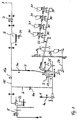
- a known grinding system is based on a circuit diagram Fig. 3 shows. Exhaust gases 3 from a calcining process from an oven fan 5 in an exhaust pipe 6 A roller mill 2 is fed via a shut-off device 6a.
- the fan is referred to as oven fan 5 here. which feeds a gas stream to a mill.
- oven fan 5 which feeds a gas stream to a mill.
- composite circuits of rotary cement kilns and heat exchangers WT with an airflow roller mill directs the furnace or Furnace / WT fan the furnace gas flow and heat flow one Roller mill, e.g. an airflow roller mill.
- a mill fan what the fan is, which one promotes the gas flow required for the mill, is in the direction of flow behind you as a dust separator functioning filter 8 a fan 7 is arranged.
- This fan 7 carries the exhaust gas 3 in the roller mill 2 resulting fines 34 via a dust exhaust pipe 9, in which a shut-off device 9a is arranged, the filter 8 too.
- the fines 34 separated in the filter 8 is about transport systems, not shown, in silos promoted.
- the dust-free exhaust gas 3 is with the help of the mill fan 7, which follows the filter 8 is fed to a chimney (not shown) and expelled.
- a shut-off device 15a In a combined operation, in which the grinding plant "on line" with a cement rotary kiln (not shown) is operated, a shut-off device 15a remains in a bypass line 15 closed. Unusable thermal energy is in one Cooling tower 22, which is usually after the furnace fan 5th is arranged, or in the roller mill 2, for example destroyed by water injection.
- the grinding plant according to FIG. 3 becomes such operated that the pressure zero point, i.e. the point atmospheric Pressure, shortly before the exhaust gases enter the Rolling mill 2 is placed, so that the rolling mill 2, an integrated Sifter 13 and the filter 8 under a relative high vacuum and appropriate sealing devices and stable constructions are required which will be explained below.
- the pressure zero point i.e. the point atmospheric Pressure
- FIG. 4 A circuit diagram of another raw material grinding drying system, which is also referred to as the "three-blower version" is shown in FIG. 4.
- a first fan which the furnace fan 5 corresponds to FIG. 3, but is not shown in the direction of flow in front of a cooling tower 22.
- Es promotes the exhaust gases 3 from the calcining process to a roller mill 2.
- a second fan 28, which acts as a mill fan acts, is located behind a cyclone battery 29 and promotes a partial gas flow via a return line 16 back to the roller mill 2. The remaining part of the exhaust gases the cyclone battery 29 becomes a control and shut-off device 14 fed to a filter 8.
- a third blower 38 is arranged as an exhaust gas fan, which the remaining exhaust gases 3 into a chimney (Not shown) promotes as a filter exhaust. That in the Cyclone battery 29 and fines 34 accumulating in the filter 8, 35 is a corresponding funding 36 Silo (not shown) fed.
- bypass line 15 can excess exhaust gas and Heat flows from the kiln's kiln and calcining process 2 with sifter 13 and cyclone battery 29 bypassed and together with the exhaust gases from the roller mill 2 in the downstream Filter system 8 are dedusted.
- FIG. 6 shows an exemplary pressure profile of the composite circuit variant the system shown in FIG. 4.
- the essential facilities are with appropriate allocation shown above the pressure curve and with reference numerals 4 provided.
- 6 illustrates that the filter 8 works in a relatively low vacuum range and therefore against false air ingresses only with a relatively small Effort must be protected.
- the roller mill 2 which operate with negative pressure around -50 to -80 mbar is almost to avoid false air ingress be hermetically sealed.
- a high degree of separation in the cyclone battery 29 is required also a relatively high energy expenditure, and as Another disadvantage of the known system is the splitting of End product in coarse fines 35 from the cyclones and to see finer product 34 from the filter 9 (Fig. 4).
- exemplary pressure curve of the compound circuit variant the system according to FIG. 3 is that Filter 8, however, in the negative pressure area of the roller mill 2, which is about -70 to -90 mbar, included and must therefore in terms of design and safety be interpreted.
- Filter housings are in large-scale Grinding plants of considerable size. The filter housing must for operational negative pressures of almost -100 mbar and for a start with cold air for safety reasons up to -140 mbar. It takes a lot more constructive and manufacturing measures to achieve the required To achieve rigidity and prevent collapse. It even sucks through small cracks in the housing downstream mill fan 7 false air into the system, which affects the mill exhaust gas as a loss and leads to malfunctions.
- the invention has for its object to provide a grinding plant and a method for grinding raw materials, in particular a plant and a method for cement production, which with a particularly low investment and maintenance effort, a variable process control and an extremely efficient grinding process, in particular an efficient cement production guarantee.
- the task is performed by a grinding plant, e.g. through a plant for the production of cement with a Roller mill, a cement rotary kiln with a heat exchanger unit, an oven fan and an exhaust fan solved behind a filter in which a mill fan is arranged in front of the roller mill, which the high Resistance of the blade ring of the roller mill overcomes and a waste gas or required for a grinding drying process also air flow through the blade ring of the roller mill presses and in cooperation with the exhaust fan advantageous pressure curve before, within and after the Rolling mill allows up to the filter.
- a grinding plant e.g. through a plant for the production of cement with a Roller mill, a cement rotary kiln with a heat exchanger unit, an oven fan and an exhaust fan solved behind a filter in which a mill fan is arranged in front of the roller mill, which the high Resistance of the blade ring of the roller mill overcomes and a waste gas or required for a grinding drying process also air flow through the blade ring of the roller mill presse
- the pressure zero point i.e. the atmospheric pressure
- the pressure zero point i.e. the atmospheric pressure
- the arrangement of a mill fan in front of a roller mill is known per se from coal grinding plants.
- the mill fan is the only fan in the coal grinding system.
- the grinding room, viewing area and e.g. the following burner lines and coal dust / air mixture burner under pressure are known per se from coal grinding plants.
- the upstream mill fan is used in a composite cement raw material grinding plant with grinding drying process to shift the pressure level so that in cooperation with the exhaust fan in the mill interior a significantly lower negative pressure up to the ambient pressure arises.
- the total performance of the fans the mill drying system i.e. of the mill fan and of the exhaust fan after the filter system, is on the Fans distributed and dropped because of the lower achieved False air fractions lower.
- the mill base is under pressure.
- the filter can be clear at one lower negative pressure than the previously usual according to circuit 3 are operated.
- the construction of the filter housing can be advantageous considerably simplified for collecting surface pressure become.
- the gas flow through the roller mill is upstream Mill fan regulated. It is advantageous that the regulation of a bypass exhaust gas flow because of the lower Pressure drop to the filter easily through the exhaust fan is possible. Because of the reduced pressure level In front of the filter, dedusting devices can also be connected to the Line connected between the roller mill and the filter become.
- the invention can be used not only in cement raw material grinding plants can be used advantageously. It is within the Invention, a grinding plant without an upstream Process, e.g. a so-called central grinding plant, with a upstream mill fan to operate the Pressure level from the negative pressure area to the positive pressure area to shift into the grinding room of the mill and over one Fan after filter, an exhaust fan, negative pressure to create. Seen in the direction of flow, the lower grinding chamber up to the intake of the exhaust fan under a lower vacuum than in conventional Grinding plants.
- a grinding plant without an upstream Process e.g. a so-called central grinding plant
- a upstream mill fan to operate the Pressure level from the negative pressure area to the positive pressure area to shift into the grinding room of the mill and over one Fan after filter, an exhaust fan, negative pressure to create. Seen in the direction of flow, the lower grinding chamber up to the intake of the exhaust fan under a lower vacuum than in conventional Grinding plants.
- a grinding plant according to the invention in which an upstream Mill fan interacts with an exhaust fan, can be used to grind various raw materials like clinker, slag sand, coal and all others Types of minerals and rocks can be applied.
- filter systems means the use of a Fan in front of the mill that an exhaust fan additional fan is used. With the so far usual filter systems the fan works behind the filter is arranged, both as a mill fan and also as an exhaust fan.
- MPL Modified Pressure Level
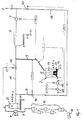
- Fig. 1 is a circuit diagram of a plant for cement production with a calcining and grinding drying process shown.
- Exhaust gases 3 from a rotary cement kiln 40 are via a Pre-calciner 41, a heat exchanger unit 42 and one Furnace fan 5 and a cooling tower 22 in an exhaust pipe 6 a mill drying process with a roller mill 2 and a filter 8, supplied.
- a filter 8 can a hose or electrostatic filter must be used.
- a mill fan 10 or mill blower arranged with which the pressure level in the area of the mill 2 and Filter 8 is raised.
- the total output of the grinding system is based on the upstream Mill fan 10 and the exhaust fan 7 distributed and is not bigger, but because of the smaller False air shares lower.
- the upstream mill fan 10 presses one for the Milling drying process required exhaust gas flow through the Blade ring 11 and thereby avoids that the blade ring 11 acts as a resistor for the exhaust gas fan 7 and a large negative pressure gradient to the atmosphere in the upper part of the mill and in the subsequent parts of the plant, in particular is built up in the filter 8.
- a control and shut-off device is located in the exhaust pipe 6 46, for example a throttle valve, which not only when the roller mill 2 is shut down Bypassing the exhaust gases 3 via a bypass line 15 and Dust removal allowed in filter 8.
- a gas flow measuring device 20 In front of the upstream mill fan 10 is a gas flow measuring device 20 arranged, the measured values for Control of the mill fan 10 can be used.
- a dust exhaust pipe 9 leads from the roller mill 2 to Filter 8.
- the fine material 34 obtained in the filter 8 becomes via transport devices, not shown, in silos promoted.
- the dedusted exhaust gas 3 can at least partially via a return line 16 via the mill fan 10 the roller mill 2 are fed again. If an adjustable Shut-off device 47 in the return line 16 closed is, the dedusted exhaust gases 3 via a Chimney directed into the atmosphere.
- Fig. 1 shows the possibilities for controlling the shut-off and control device 46 in the exhaust pipe 6, a control and shut-off device 48 in the bypass line 15, the control and shut-off device 47 in the return line 16 and in the dust exhaust pipe 9.
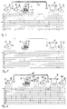
- the defined pressure curve, which with an upstream Mill fan 10 in cooperation with an exhaust fan 7 in the mill drying system according to FIG. 1 can be achieved is shown by way of example in FIG. 2.
- FIG. 2 illustrates the modified Pressure level before, inside and after the roller mill 2 as well in the filter 8.
- the negative pressure in the electrostatic filter is particularly disadvantageous in the known system according to FIGS. 3 and 5, which is around -90 mbar.
- Fig. 2 illustrates that with the upstream mill fan 10 immediately in front of the roller mill 2 or in the lower part of the mill and in front of the blade ring 11 an overpressure, e.g. of about 40 mbar.
- the pressure zero point is operationally safe in an upper area of the Blade ring 11 up to an upper edge of the grinding bowl 12.
- the MPL process (Modified Pressure Level) is therefore preceded by a shifted pressure level, marked inside and after the roller mill 2, which in cooperation with the upstream mill fan 10 is achieved with the exhaust fan 7 and extraordinary Savings in investment and energy costs, Maintenance costs and at a particularly efficient Shredding of raw materials and in particular to one leads to efficient cement production.
Landscapes
- Engineering & Computer Science (AREA)
- Food Science & Technology (AREA)
- Crushing And Grinding (AREA)
- Disintegrating Or Milling (AREA)
- Fertilizers (AREA)
Abstract
Description
- Fig. 1
- ein Anlagenschema einer erfindungsgemäßen Mahlanlage und
- Fig. 2
- eine schematische Darstellung eines beispielhaften Druckverlaufs der erfindungsgemäßen Verbund-Schaltungsvariante gemäß Fig. 1.
- Fig. 3 und 4
- zeigen Anlagen- und Schaltungsbilder des Standes der Technik und
- Fig. 5 und 6
- die zugehörigen beispielhaften Druckverläufe.
Claims (20)
- Mahlanlage
mit einer Wälzmühle (2), insbesondere einer Luftstrom-Wälzmühle, mit einer Mahlschüssel (12), einem Schaufelkranz (11) und einem Sichter (13) und mit einem Ventilator (7), welcher nach einem Filter (8) angeordnet ist und das Filter (8), die Wälzmühle (2) und eine Staub-Gas-Rohrleitung (9) zwischen dem Filter (8) und der Wälzmühle (2) mit Unterdruck beaufschlagt,
dadurch gekennzeichnet,daß ein Mühlenventilator (10) vor der Wälzmühle (2) angeordnet ist und den erforderlichen Gasstrom in die Wälzmühle (2) drückt unddaß ein vorgebbares Druckniveau vor, innerhalb und nach der Wälzmühle (2) von dem Mühlenventilator (10) und dem Abgasventilator (7) einstellbar ist. - Mahlanlage nach Anspruch 1,
dadurch gekennzeichnet,daß der Mühlenventilator (10) der Wälzmühle (2) vorgeschaltet und der Druck-Nullpunkt in den Bereich des Schaufelkranzes (11) und der Mahlschüssel (12) legbar ist. - Anlage zur Herstellung von Zement,
mit einer Wälzmühle (2), in welcher in Verbundschaltung mit einem Zement-Drehrohrofen (40) und einer Wärmetauschereinheit (42) Zement-Rohmaterial mit Abgasen (3) des Zement-Drehrohrofens (40) einer Mahltrocknung unterzogen wird, mit einem Ofenventilator (5), welcher nach der Wärmetauschereinheit (42) angeordnet ist und die Abgase (3) aus dem Zement-Drehrohrofen (40) einer Abgas-Rohrleitung (6) zuführt, und mit einem Abgasventilator (7), welcher nach einem Filter (8) angeordnet ist und das Filter (8), die Wälzmühle (2) mit einem Schaufelkranz (11), einer Mahlschüssel (12) und einem Sichter (13) sowie eine Staub-Abgas-Rohrleitung (9) zwischen dem Filter (8) und der Wälzmühle (2) mit Unterdruck beaufschlagt,
dadurch gekennzeichnet,daß ein Mühlenventilator (10) vor der Wälzmühle (2) angeordnet ist und den erforderlichen Gasstrom in die Wälzmühle (2) drückt, und daß ein vorgebbares Druckniveau vor, innerhalb und nach der Wälzmühle (2) einstellbar und der Druck-Nullpunkt in den Bereich des Schaufelkranzes (11) und der Mahlschüssel (12) legbar ist. - Anlage nach einem der Ansprüche 1 bis 3,
dadurch gekennzeichnet,daß in einem oberen Bereich des Schaufelkranzes (11) bis zu einer oberen Kante der Mahlschüssel (12) der Druck-Nullpunkt bzw. ein minimaler Unterdruck einstellbar ist. - Anlage nach einem der Ansprüche 1 bis 4,
dadurch gekennzeichnet,daß mit dem vorgeschalteten Mühlenventilator (10) vor und innerhalb der Wälzmühle (2) unterhalb des Schaufelkranzes (11) ein Überdruck und oberhalb der Mahlschüssel (12) und im Bereich des Sichters (13), welcher in die Wälzmühle (2) integriert ist, ein Unterdruck einstellbar ist. - Anlage nach einem der Ansprüche 1 bis 5,
dadurch gekennzeichnet,daß in dem Filter (8) ein Unterdruck einstellbar ist und das Filter (8) eine relativ leichte Gehäusekonstruktion aufweist. - Anlage nach einem der Ansprüche 1 bis 6,
dadurch gekennzeichnet,daß die Wälzmühle (2) vereinfachte Abdichtungen, insbesondere im Bereich der Rohmaterial-Aufgabe und der Durchtritte bewegter Teile durch das Mühlengehäuse aufweist. - Anlage nach einem der Ansprüche 1 bis 7,
dadurch gekennzeichnet,daß Entstaubungseinrichtungen an die Staub-Abgas-Rohrleitung (9) anschließbar sind. - Anlage nach einem der Ansprüche 3 bis 8,
dadurch gekennzeichnet,daß eine Bypass-Leitung (15) zur Zuführung von Abgasen (3) aus dem Zement-Drehrohrofen (40) vorgesehen ist und daß die Bypass-Leitung (15) in Strömungsrictung vor einer Regel- und Absperreinrichtung (46) von der Abgas-Rohrleitung (6) abzweigt. - Anlage nach einem der Ansprüche 3 bis 9,
dadurch gekennzeichnet,daß der Gasstrom zum Filter (8) weitestgehend unabhängig vom Gasstrom durch die Wälzmühle (2) hinsichtlich Volumenstrom und Gastemperatur konditionierbar ist. - Anlage nach einem der Ansprüche 3 bis 10,
dadurch gekennzeichnet,daß nach dem Filter (8) zur Rückführung regelbarer Gasströme in die Wälzmühle (2) eine Rückführleitung (16) angeordnet ist. - Anlage nach Anspruch 11,
dadurch gekennzeichnet,daß in der Abgas-Rohrleitung (6) sowie in der Bypass-Leitung (15) und in der Rückführleitung (16) Regel- und Absperreinrichtungen (46, 47, 48) angeordnet sind. - Anlage nach einem der Ansprüche 1 bis 12,
dadurch gekennzeichnet,daß eine Gasstrommeßeinrichtung (20) vor dem Mühlenventilator (10) in der Zuführleitung zur Wälzmühle (2) angeordnet ist. - Verfahren zur Herstellung von Zement in einem Verbundsystem, bei welchem eine Rohmaterial-Mischung (33) in einer Wälzmühle (2) unter Zufuhr von Abgasen (3) aus einem Kalzinierprozeß einer Mahltrocknung unterzogen, gesichtet und als Staub-Abgas-Gemisch einem Filter (8) zur Staubabtrennung aus dem Abgas (3) zugeführt wird und die Abgase (3) mit Hilfe eines Ofenventilators (5) nach dem Kalzinieren und Vorwärmen von Rohmehl sowie mit einem Ventilator (7) nach einem Filter (8) durch die Wälzmühle (2) und das Filter (8) in einer Verbundschaltung geführt werden, insbesondere in einer Anlage nach einem der Ansprüche 3 bis 13,
dadurch gekennzeichnet,daß eine regelbare Abgasmenge mit einem Mühlenventilator (10) vor der Wälzmühle (2) in die Wälzmühle (2) und durch deren Schaufelkranz (11) gedrückt wird, daß der Druck-Nullpunkt in die Ebene des Schaufelkranzes (11) und der Mahlschüssel (12) der Wälzmühle (2) gelegt wird und daß oberhalb des Schaufelkranzes (11) bis in das Filter (8) ein geringer Unterdruck eingestellt wird. - Verfahren nach Anspruch 14,
dadurch gekennzeichnet,daß vor und unterhalb des Schaufelkranzes (11) der Wälzmühle (2) durch den vorgeschalteten Mühlenventilator (10) ein Überdruck von beispielsweise 40 bis 50 mbar eingestellt wird. - Verfahren nach Anspruch 14 oder 15,
dadurch gekennzeichnet,daß im Bereich des Schaufelkranzes (11) und der Mahlschüssel (12) ein Unterdruck, insbesondere von etwa -3 bis -5 mbar, und im Bereich des Sichters (13), der Staub-Abgas-Rohrleitung (9) sowie in dem Filter (8) ein Unterdruck von beispielsweise -25 bis -45 mbar eingestellt wird. - Verfahren nach einem der Ansprüche 14 bis 16,
dadurch gekennzeichnet,daß das Abgas (3) aus dem Kalzinierprozeß wenigstens teilweise in einer Bypass-Leitung (15) direkt dem Filter (8) zugeführt und unabhängig vom Gasstrom durch die Wälzmühle (2) hinsichtlich Volumenstrom und Gastemperatur konditioniert wird. - Verfahren nach einem der Ansprüche 14 bis 17,
dadurch gekennzeichnet,daß das Abgas (3) nach dem Filter (8) und dem Anlagenventilator (7) wenigstens teilweise zur Mühle (2) zurückgeführt wird. - Verfahren nach einem der Ansprüche 14 bis 18,
dadurch gekennzeichnet,daß durch den vorgeschalteten Mühlenventilator (10) das Druckniveau in der Wälzmühle (2) bis in den Filter (8) angehoben wird. - Verfahren nach einem der Ansprüche 14 bis 19,
dadurch gekennzeichnet,daß Abgase (3) anderer Mahlsysteme dem Filter (8) zugeführt und entstaubt werden.
Applications Claiming Priority (2)
| Application Number | Priority Date | Filing Date | Title |
|---|---|---|---|
| DE19836323 | 1998-08-11 | ||
| DE19836323A DE19836323C2 (de) | 1998-08-11 | 1998-08-11 | Mahlanlage, Anlage zur Herstellung von Zement und Verfahren zur Vermahlung von Rohmaterialien |
Publications (3)
| Publication Number | Publication Date |
|---|---|
| EP0979675A1 true EP0979675A1 (de) | 2000-02-16 |
| EP0979675B1 EP0979675B1 (de) | 2010-09-15 |
| EP0979675B8 EP0979675B8 (de) | 2010-12-29 |
Family
ID=7877170
Family Applications (1)
| Application Number | Title | Priority Date | Filing Date |
|---|---|---|---|
| EP99112848A Expired - Lifetime EP0979675B8 (de) | 1998-08-11 | 1999-07-02 | Mahlanlage und Verfahren zur Vermahlung von Rohmaterialien |
Country Status (8)
| Country | Link |
|---|---|
| US (2) | US6276620B1 (de) |
| EP (1) | EP0979675B8 (de) |
| JP (1) | JP3933820B2 (de) |
| AT (1) | ATE481175T1 (de) |
| CA (1) | CA2279086C (de) |
| DE (1) | DE19836323C2 (de) |
| DK (1) | DK0979675T3 (de) |
| ES (1) | ES2351083T3 (de) |
Cited By (2)
| Publication number | Priority date | Publication date | Assignee | Title |
|---|---|---|---|---|
| CN101559397B (zh) * | 2009-05-27 | 2010-12-01 | 辽宁艾海滑石有限公司 | 微负压雷蒙磨粉机粉磨系统 |
| WO2013143565A1 (de) * | 2012-10-17 | 2013-10-03 | Loesche Gmbh | Verfahren und vorrichtung zur vermahlung von feuchtem material |
Families Citing this family (24)
| Publication number | Priority date | Publication date | Assignee | Title |
|---|---|---|---|---|
| DE19836323C2 (de) * | 1998-08-11 | 2000-11-23 | Loesche Gmbh | Mahlanlage, Anlage zur Herstellung von Zement und Verfahren zur Vermahlung von Rohmaterialien |
| DE10050332C2 (de) * | 2000-10-11 | 2003-11-27 | Loesche Gmbh | Verfahren und Vorrichtung zur Präparierung von Brennstoffen |
| DE10152991A1 (de) * | 2001-10-26 | 2003-05-08 | Wolff Walsrode Ag | Verfahren und Vorrichtung zur Mahltrocknung |
| JP4477635B2 (ja) * | 2003-09-12 | 2010-06-09 | ロエシェ ゲーエムベーハー | ローラ粉砕ミル及びその運転方法並びにセメントの製造方法 |
| DE10343218B4 (de) * | 2003-09-12 | 2006-05-04 | Loesche Gmbh | Sicherheitssystem für eine Wälzmühle und Verfahren zur Herstellung von Zement |
| DE102004003068A1 (de) * | 2004-01-21 | 2005-08-11 | Khd Humboldt Wedag Ag | Zementklinkerherstellung mit Teilstromabzug schadstoffhaltigen Drehofenabgases |
| DE102005026425A1 (de) * | 2005-06-08 | 2006-12-14 | Polysius Ag | Vorrichtung und Verfahren zum Trocknen und Desagglomerieren |
| DE102005040519B4 (de) * | 2005-08-26 | 2009-12-31 | Loesche Gmbh | Verfahren und Vorrichtung zur Vermahlung von heißem und feuchtem Rohmaterial |
| JP4953067B2 (ja) * | 2007-01-26 | 2012-06-13 | 宇部興産機械株式会社 | 竪型粉砕機の制御方法 |
| JP2010059383A (ja) * | 2008-09-08 | 2010-03-18 | Mitsubishi Heavy Ind Ltd | ガス化炉装置 |
| US9250018B2 (en) * | 2009-11-06 | 2016-02-02 | Fives North American Combustion, Inc. | Apparatus and methods for achieving low NOx in a grate-kiln pelletizing furnace |
| DE102010018046A1 (de) | 2010-04-23 | 2011-10-27 | Loesche Gmbh | Verfahren zur Vermahlung von Mahlgut |
| ES2390724B1 (es) * | 2010-08-31 | 2013-11-06 | Salvador Gutierrez Mainar | Instalacion y metodo para la fabricacion de cemento |
| CN102872963A (zh) * | 2012-10-25 | 2013-01-16 | 南通新邦化工科技有限公司 | 片状和团块状硬脂酸盐粉碎流程及设备 |
| CN104525341A (zh) * | 2014-12-31 | 2015-04-22 | 江苏天琦生物科技有限公司 | 一种气流干燥器 |
| LU92916B1 (en) * | 2015-12-17 | 2017-07-13 | Wurth Paul Sa | Grinding and drying plant |
| CN105772197B (zh) * | 2016-03-15 | 2019-05-03 | 东莞市五全机械有限公司 | 一种超微细辊磨机设备生产流程 |
| CN108339592B (zh) * | 2017-12-26 | 2021-06-04 | 安徽苏源矿业有限公司 | 一种矿石挤压粉碎研磨筛选装置 |
| CN108398481B (zh) * | 2018-01-22 | 2019-03-05 | 中国科学院地质与地球物理研究所 | 一种分析金属硫化物中的包裹体气相成分的方法 |
| CN109365063B (zh) * | 2018-10-19 | 2023-09-08 | 四川亿欣新材料有限公司 | 一种多叶轮立磨机 |
| CN112156855A (zh) * | 2020-10-13 | 2021-01-01 | 南京凯盛国际工程有限公司 | 一种制砂系统及其操作方法 |
| CN112958224A (zh) * | 2021-01-27 | 2021-06-15 | 郭瑜 | 磨煤机旋转喷嘴动静环结构 |
| CN115254281B (zh) * | 2022-07-22 | 2023-05-23 | 江西格林循环产业股份有限公司 | 一种防粘结的破碎机 |
| AT525912B1 (de) * | 2022-08-03 | 2023-09-15 | Scheuch Man Holding Gmbh | Verfahren zur Zementherstellung mit Schleusenvorrichtungen, Filteranlage und Zementherstellungsanlage |
Citations (7)
| Publication number | Priority date | Publication date | Assignee | Title |
|---|---|---|---|---|
| DE2930524A1 (de) * | 1979-07-27 | 1981-02-19 | Kloeckner Humboldt Deutz Ag | Verfahren und vorrichtung zur vermahlung und trocknung von feuchtem stueckgut |
| EP0068681A2 (de) * | 1981-06-26 | 1983-01-05 | F.L. Smidth & Co. A/S | Vertikale Rollermühle |
| EP0154281A2 (de) * | 1984-02-28 | 1985-09-11 | Klöckner-Humboldt-Deutz Aktiengesellschaft | Verfahren und Vorrichtung zur Herstellung von Zement |
| EP0164512A1 (de) | 1984-05-16 | 1985-12-18 | Krupp Polysius Ag | Mahlverfahren sowie Mahlanlage |
| DE4224704A1 (de) * | 1992-07-25 | 1994-01-27 | Zementanlagen Und Maschinenbau | Verfahren und anlagentechnische Schaltung zur Zerkleinerung von Mahlgut, vorzugsweise Zementklinker |
| EP0634219A1 (de) * | 1993-07-14 | 1995-01-18 | Loesche Gmbh | Verfahren und Einrichtung zum Zerkleinern von Material unterschiedlicher Körnung |
| EP0842702A1 (de) * | 1996-11-15 | 1998-05-20 | Joseph E. Dipl.-Ing. Doumet | Verfahren und Rollenmühle zum Trocknen und Mahlen von feuchtem Mahlgut |
Family Cites Families (11)
| Publication number | Priority date | Publication date | Assignee | Title |
|---|---|---|---|---|
| DE2361060B2 (de) * | 1973-12-07 | 1978-05-11 | Loesche Hartzerkleinerungs- Und Zementmaschinen Kg, 4000 Duesseldorf | Anlage und Verfahren zur Herstellung von Zement |
| US4461428A (en) * | 1982-02-18 | 1984-07-24 | Williams Patent Crusher And Pulverizer Company | Apparatus for reducing fraible materials into coarse and fine fractions |
| US4498633A (en) * | 1982-11-04 | 1985-02-12 | Williams Patent Crusher And Pulverizer Company | Apparatus for processing coal |
| US4505435A (en) * | 1983-05-16 | 1985-03-19 | Combustion Engineering, Inc. | Apparatus for removal of troublesome mineral matter from pulverized coal |
| DE3502957A1 (de) * | 1985-01-30 | 1986-07-31 | Readymix Zementwerke GmbH & Co KG, 4720 Beckum | Verfahren und vorrichtung zum herstellen von zementklinker |
| US4640204A (en) * | 1986-06-09 | 1987-02-03 | Williams Patent Crusher And Pulverizer Company | Fluidized bed combustion apparatus and method of operating same |
| DE4306930B4 (de) * | 1992-07-25 | 2005-11-10 | Khd Humboldt Wedag Ag | Anlage zur Zerkleinerung von Mahlgut |
| US5769332A (en) * | 1996-04-10 | 1998-06-23 | Cgc Inc. | Efficient production of landplaster by collecting and classsifying gypsum fines |
| US5839673A (en) * | 1996-09-10 | 1998-11-24 | Williams; Robert M. | Apparatus for grinding material |
| DE19641781A1 (de) * | 1996-10-10 | 1998-04-16 | Clariant Gmbh | Verfahren und Vorrichtung zum gleichzeitigen Mahlen und Trocknen eines feuchten Celluloseether enthaltenden Mahlgutes |
| DE19836323C2 (de) * | 1998-08-11 | 2000-11-23 | Loesche Gmbh | Mahlanlage, Anlage zur Herstellung von Zement und Verfahren zur Vermahlung von Rohmaterialien |
-
1998
- 1998-08-11 DE DE19836323A patent/DE19836323C2/de not_active Expired - Fee Related
-
1999
- 1999-07-02 ES ES99112848T patent/ES2351083T3/es not_active Expired - Lifetime
- 1999-07-02 AT AT99112848T patent/ATE481175T1/de active
- 1999-07-02 EP EP99112848A patent/EP0979675B8/de not_active Expired - Lifetime
- 1999-07-02 DK DK99112848.9T patent/DK0979675T3/da active
- 1999-07-29 CA CA002279086A patent/CA2279086C/en not_active Expired - Fee Related
- 1999-08-04 US US09/366,954 patent/US6276620B1/en not_active Expired - Lifetime
- 1999-08-09 JP JP22570799A patent/JP3933820B2/ja not_active Expired - Fee Related
-
2001
- 2001-08-15 US US09/929,337 patent/US6685117B2/en not_active Expired - Fee Related
Patent Citations (7)
| Publication number | Priority date | Publication date | Assignee | Title |
|---|---|---|---|---|
| DE2930524A1 (de) * | 1979-07-27 | 1981-02-19 | Kloeckner Humboldt Deutz Ag | Verfahren und vorrichtung zur vermahlung und trocknung von feuchtem stueckgut |
| EP0068681A2 (de) * | 1981-06-26 | 1983-01-05 | F.L. Smidth & Co. A/S | Vertikale Rollermühle |
| EP0154281A2 (de) * | 1984-02-28 | 1985-09-11 | Klöckner-Humboldt-Deutz Aktiengesellschaft | Verfahren und Vorrichtung zur Herstellung von Zement |
| EP0164512A1 (de) | 1984-05-16 | 1985-12-18 | Krupp Polysius Ag | Mahlverfahren sowie Mahlanlage |
| DE4224704A1 (de) * | 1992-07-25 | 1994-01-27 | Zementanlagen Und Maschinenbau | Verfahren und anlagentechnische Schaltung zur Zerkleinerung von Mahlgut, vorzugsweise Zementklinker |
| EP0634219A1 (de) * | 1993-07-14 | 1995-01-18 | Loesche Gmbh | Verfahren und Einrichtung zum Zerkleinern von Material unterschiedlicher Körnung |
| EP0842702A1 (de) * | 1996-11-15 | 1998-05-20 | Joseph E. Dipl.-Ing. Doumet | Verfahren und Rollenmühle zum Trocknen und Mahlen von feuchtem Mahlgut |
Cited By (2)
| Publication number | Priority date | Publication date | Assignee | Title |
|---|---|---|---|---|
| CN101559397B (zh) * | 2009-05-27 | 2010-12-01 | 辽宁艾海滑石有限公司 | 微负压雷蒙磨粉机粉磨系统 |
| WO2013143565A1 (de) * | 2012-10-17 | 2013-10-03 | Loesche Gmbh | Verfahren und vorrichtung zur vermahlung von feuchtem material |
Also Published As
| Publication number | Publication date |
|---|---|
| EP0979675B1 (de) | 2010-09-15 |
| DE19836323A1 (de) | 2000-02-24 |
| US20020023976A1 (en) | 2002-02-28 |
| EP0979675B8 (de) | 2010-12-29 |
| CA2279086A1 (en) | 2000-02-11 |
| DK0979675T3 (da) | 2011-01-10 |
| US6685117B2 (en) | 2004-02-03 |
| JP2000079352A (ja) | 2000-03-21 |
| ATE481175T1 (de) | 2010-10-15 |
| ES2351083T3 (es) | 2011-01-31 |
| US6276620B1 (en) | 2001-08-21 |
| JP3933820B2 (ja) | 2007-06-20 |
| DE19836323C2 (de) | 2000-11-23 |
| CA2279086C (en) | 2006-01-10 |
Similar Documents
| Publication | Publication Date | Title |
|---|---|---|
| EP0979675B1 (de) | Mahlanlage und Vefahren zur Vermahlung von Rohmaterialien | |
| DE102005040519B4 (de) | Verfahren und Vorrichtung zur Vermahlung von heißem und feuchtem Rohmaterial | |
| DE2745425A1 (de) | Verfahren und vorrichtung zur erzeugung von kohlenstaub | |
| DE3010909A1 (de) | Verfahren und vorrichtung zum brennen von feinkoernigen gut und zur erzeugung von kohlenstaub | |
| EP0678487B1 (de) | Verfahren und Anlage zur Kühlung von Weisszementklinker | |
| EP1214155B1 (de) | Verfahren und windsichter zum klassieren von zerkleinertem aufgabegut | |
| DE2745424A1 (de) | Verfahren und vorrichtung zur trocknung und feinmahlung von kohle | |
| EP2655271A1 (de) | Vorrichtung zum vorwärmen von beschickungsgut für glasschmelzanlagen | |
| DE2850895C2 (de) | Verfahren und Vorrichtung zur Erzeugung von Kohlenstaub | |
| WO2012159776A1 (de) | Anlage und verfahren zur mahltrocknung und einlagerung von braunkohle | |
| DE102018215348A1 (de) | Kühler zum Kühlen von Klinker und Verfahren zum Betreiben eines Kühlers zum Kühlen von Klinker | |
| EP0030376B1 (de) | Verfahren und Vorrichtung zum Trocknen und Erhitzen von feuchter Kohle | |
| DE3407154A1 (de) | Verfahren und vorrichtung zur herstellung von zement | |
| DE2451197A1 (de) | Verfahren und vorrichtung zum calzinieren von pulvermaterial | |
| DE2845980A1 (de) | Verfahren und vorrichtung zur inertisierung eines brennbares gut enthaltenden anlagensystemes | |
| DE2333560C2 (de) | Sinteranlage zur Herstellung von Sinter aus Eisenerzen | |
| DE2846584A1 (de) | Verfahren und vorrichtung zur waermebehandlung von feinkoernigem gut | |
| DE102008044709A1 (de) | Verfahren und Vorrichtung zum Fördern von Verbrennungsrückständen | |
| DE4100232C2 (de) | Einrichtung zur Regelung des in einem Ofenraum herrschenden Gasdrucks | |
| DE102022102561B4 (de) | Verfahren zum Betrieb einer Anlage zur Herstellung von Zementklinker und entsprechende Anlage | |
| DE3025512A1 (de) | Verfahren zum an- und/oder abfahren von inert betriebenen mahltrocknungsanlagen | |
| DE1796018A1 (de) | Verfahren und Vorrichtung zur Herstellung von Zementklinker | |
| DE202004009704U1 (de) | Vorrichtung zur Granulation flüssiger Schlacken | |
| DE2429721C2 (de) | Anlage zum Brennen von Zementklinker und Verfahren zum Betrieb einer solchen Anlage | |
| DE2608721A1 (de) | Vorrichtung zur trennung eines gemisches aus schrott und schutt |
Legal Events
| Date | Code | Title | Description |
|---|---|---|---|
| PUAI | Public reference made under article 153(3) epc to a published international application that has entered the european phase |
Free format text: ORIGINAL CODE: 0009012 |
|
| AK | Designated contracting states |
Kind code of ref document: A1 Designated state(s): AT BE CH CY DE DK ES FI FR GB GR IE IT LI LU MC NL PT SE |
|
| AX | Request for extension of the european patent |
Free format text: AL;LT;LV;MK;RO;SI |
|
| 17P | Request for examination filed |
Effective date: 20000228 |
|
| AKX | Designation fees paid |
Free format text: AT BE CH CY DE DK ES FI FR GB GR IE IT LI LU MC NL PT SE |
|
| 17Q | First examination report despatched |
Effective date: 20061109 |
|
| GRAP | Despatch of communication of intention to grant a patent |
Free format text: ORIGINAL CODE: EPIDOSNIGR1 |
|
| GRAS | Grant fee paid |
Free format text: ORIGINAL CODE: EPIDOSNIGR3 |
|
| RBV | Designated contracting states (corrected) |
Designated state(s): AT BE CH CY DK ES FI FR GB GR IE IT LI LU MC NL PT SE |
|
| REG | Reference to a national code |
Ref country code: DE Ref legal event code: 8566 |
|
| GRAA | (expected) grant |
Free format text: ORIGINAL CODE: 0009210 |
|
| AK | Designated contracting states |
Kind code of ref document: B1 Designated state(s): AT BE CH CY DK ES FI FR GB GR IE IT LI LU MC NL PT SE |
|
| REG | Reference to a national code |
Ref country code: GB Ref legal event code: FG4D Free format text: NOT ENGLISH Ref country code: CH Ref legal event code: EP |
|
| REG | Reference to a national code |
Ref country code: NL Ref legal event code: T3 |
|
| REG | Reference to a national code |
Ref country code: IE Ref legal event code: FG4D Free format text: LANGUAGE OF EP DOCUMENT: GERMAN |
|
| REG | Reference to a national code |
Ref country code: CH Ref legal event code: NV Representative=s name: BOGENSBERGER PATENT- & MARKENBUERO DR. BURKHARD BO |
|
| REG | Reference to a national code |
Ref country code: DK Ref legal event code: T3 |
|
| PG25 | Lapsed in a contracting state [announced via postgrant information from national office to epo] |
Ref country code: FI Free format text: LAPSE BECAUSE OF FAILURE TO SUBMIT A TRANSLATION OF THE DESCRIPTION OR TO PAY THE FEE WITHIN THE PRESCRIBED TIME-LIMIT Effective date: 20100915 |
|
| REG | Reference to a national code |
Ref country code: ES Ref legal event code: FG2A Effective date: 20110119 |
|
| PG25 | Lapsed in a contracting state [announced via postgrant information from national office to epo] |
Ref country code: CY Free format text: LAPSE BECAUSE OF FAILURE TO SUBMIT A TRANSLATION OF THE DESCRIPTION OR TO PAY THE FEE WITHIN THE PRESCRIBED TIME-LIMIT Effective date: 20100915 |
|
| PG25 | Lapsed in a contracting state [announced via postgrant information from national office to epo] |
Ref country code: SE Free format text: LAPSE BECAUSE OF FAILURE TO SUBMIT A TRANSLATION OF THE DESCRIPTION OR TO PAY THE FEE WITHIN THE PRESCRIBED TIME-LIMIT Effective date: 20100915 |
|
| REG | Reference to a national code |
Ref country code: IE Ref legal event code: FD4D |
|
| PG25 | Lapsed in a contracting state [announced via postgrant information from national office to epo] |
Ref country code: IE Free format text: LAPSE BECAUSE OF FAILURE TO SUBMIT A TRANSLATION OF THE DESCRIPTION OR TO PAY THE FEE WITHIN THE PRESCRIBED TIME-LIMIT Effective date: 20100915 |
|
| PG25 | Lapsed in a contracting state [announced via postgrant information from national office to epo] |
Ref country code: PT Free format text: LAPSE BECAUSE OF FAILURE TO SUBMIT A TRANSLATION OF THE DESCRIPTION OR TO PAY THE FEE WITHIN THE PRESCRIBED TIME-LIMIT Effective date: 20110117 |
|
| PLBE | No opposition filed within time limit |
Free format text: ORIGINAL CODE: 0009261 |
|
| STAA | Information on the status of an ep patent application or granted ep patent |
Free format text: STATUS: NO OPPOSITION FILED WITHIN TIME LIMIT |
|
| 26N | No opposition filed |
Effective date: 20110616 |
|
| PGFP | Annual fee paid to national office [announced via postgrant information from national office to epo] |
Ref country code: CH Payment date: 20110719 Year of fee payment: 13 Ref country code: DK Payment date: 20110704 Year of fee payment: 13 |
|
| PG25 | Lapsed in a contracting state [announced via postgrant information from national office to epo] |
Ref country code: MC Free format text: LAPSE BECAUSE OF NON-PAYMENT OF DUE FEES Effective date: 20110731 |
|
| PGFP | Annual fee paid to national office [announced via postgrant information from national office to epo] |
Ref country code: GB Payment date: 20120619 Year of fee payment: 14 |
|
| PGFP | Annual fee paid to national office [announced via postgrant information from national office to epo] |
Ref country code: GR Payment date: 20120730 Year of fee payment: 14 |
|
| PGFP | Annual fee paid to national office [announced via postgrant information from national office to epo] |
Ref country code: BE Payment date: 20120723 Year of fee payment: 14 Ref country code: FR Payment date: 20120816 Year of fee payment: 14 Ref country code: IT Payment date: 20120725 Year of fee payment: 14 Ref country code: ES Payment date: 20120703 Year of fee payment: 14 |
|
| PGFP | Annual fee paid to national office [announced via postgrant information from national office to epo] |
Ref country code: NL Payment date: 20120719 Year of fee payment: 14 |
|
| PGFP | Annual fee paid to national office [announced via postgrant information from national office to epo] |
Ref country code: AT Payment date: 20120726 Year of fee payment: 14 |
|
| PG25 | Lapsed in a contracting state [announced via postgrant information from national office to epo] |
Ref country code: LU Free format text: LAPSE BECAUSE OF NON-PAYMENT OF DUE FEES Effective date: 20110702 |
|
| REG | Reference to a national code |
Ref country code: CH Ref legal event code: PCAR Free format text: NEW ADDRESS: FALLSGASSE 7, 9492 ESCHEN (LI) |
|
| BERE | Be: lapsed |
Owner name: LOESCHE G.M.B.H. Effective date: 20130731 |
|
| REG | Reference to a national code |
Ref country code: NL Ref legal event code: V1 Effective date: 20140201 |
|
| REG | Reference to a national code |
Ref country code: DK Ref legal event code: EBP Effective date: 20130731 |
|
| REG | Reference to a national code |
Ref country code: CH Ref legal event code: PL |
|
| REG | Reference to a national code |
Ref country code: AT Ref legal event code: MM01 Ref document number: 481175 Country of ref document: AT Kind code of ref document: T Effective date: 20130702 |
|
| GBPC | Gb: european patent ceased through non-payment of renewal fee |
Effective date: 20130702 |
|
| REG | Reference to a national code |
Ref country code: GR Ref legal event code: ML Ref document number: 20100402941 Country of ref document: GR Effective date: 20140204 |
|
| REG | Reference to a national code |
Ref country code: FR Ref legal event code: ST Effective date: 20140331 |
|
| PG25 | Lapsed in a contracting state [announced via postgrant information from national office to epo] |
Ref country code: LI Free format text: LAPSE BECAUSE OF NON-PAYMENT OF DUE FEES Effective date: 20130731 Ref country code: BE Free format text: LAPSE BECAUSE OF NON-PAYMENT OF DUE FEES Effective date: 20130731 Ref country code: NL Free format text: LAPSE BECAUSE OF NON-PAYMENT OF DUE FEES Effective date: 20140201 Ref country code: GB Free format text: LAPSE BECAUSE OF NON-PAYMENT OF DUE FEES Effective date: 20130702 Ref country code: CH Free format text: LAPSE BECAUSE OF NON-PAYMENT OF DUE FEES Effective date: 20130731 |
|
| PG25 | Lapsed in a contracting state [announced via postgrant information from national office to epo] |
Ref country code: FR Free format text: LAPSE BECAUSE OF NON-PAYMENT OF DUE FEES Effective date: 20130731 Ref country code: AT Free format text: LAPSE BECAUSE OF NON-PAYMENT OF DUE FEES Effective date: 20130702 Ref country code: GR Free format text: LAPSE BECAUSE OF NON-PAYMENT OF DUE FEES Effective date: 20140204 Ref country code: IT Free format text: LAPSE BECAUSE OF NON-PAYMENT OF DUE FEES Effective date: 20130702 |
|
| PG25 | Lapsed in a contracting state [announced via postgrant information from national office to epo] |
Ref country code: DK Free format text: LAPSE BECAUSE OF NON-PAYMENT OF DUE FEES Effective date: 20130731 |
|
| REG | Reference to a national code |
Ref country code: ES Ref legal event code: FD2A Effective date: 20150710 |
|
| PG25 | Lapsed in a contracting state [announced via postgrant information from national office to epo] |
Ref country code: ES Free format text: LAPSE BECAUSE OF NON-PAYMENT OF DUE FEES Effective date: 20130703 |
|
| REG | Reference to a national code |
Ref country code: GR Ref legal event code: EP Ref document number: 20100402941 Country of ref document: GR Effective date: 20110119 |