EP0978835A2 - Wiederauffindung von Daten mit schlangenförmigemmuster - Google Patents
Wiederauffindung von Daten mit schlangenförmigemmuster Download PDFInfo
- Publication number
- EP0978835A2 EP0978835A2 EP99306064A EP99306064A EP0978835A2 EP 0978835 A2 EP0978835 A2 EP 0978835A2 EP 99306064 A EP99306064 A EP 99306064A EP 99306064 A EP99306064 A EP 99306064A EP 0978835 A2 EP0978835 A2 EP 0978835A2
- Authority
- EP
- European Patent Office
- Prior art keywords
- tape
- drive
- media
- cartridge
- data
- Prior art date
- Legal status (The legal status is an assumption and is not a legal conclusion. Google has not performed a legal analysis and makes no representation as to the accuracy of the status listed.)
- Ceased
Links
- 238000000034 method Methods 0.000 claims abstract description 33
- 238000013500 data storage Methods 0.000 claims abstract description 30
- 230000008569 process Effects 0.000 claims abstract description 22
- 230000007246 mechanism Effects 0.000 claims abstract description 10
- WYTGDNHDOZPMIW-RCBQFDQVSA-N alstonine Natural products C1=CC2=C3C=CC=CC3=NC2=C2N1C[C@H]1[C@H](C)OC=C(C(=O)OC)[C@H]1C2 WYTGDNHDOZPMIW-RCBQFDQVSA-N 0.000 description 6
- 238000010586 diagram Methods 0.000 description 5
- 230000032258 transport Effects 0.000 description 2
- 230000007175 bidirectional communication Effects 0.000 description 1
- 230000006854 communication Effects 0.000 description 1
- 238000004891 communication Methods 0.000 description 1
- 238000007418 data mining Methods 0.000 description 1
- 230000006870 function Effects 0.000 description 1
- 230000003287 optical effect Effects 0.000 description 1
- 239000004065 semiconductor Substances 0.000 description 1
Images


Classifications
-
- G—PHYSICS
- G11—INFORMATION STORAGE
- G11B—INFORMATION STORAGE BASED ON RELATIVE MOVEMENT BETWEEN RECORD CARRIER AND TRANSDUCER
- G11B23/00—Record carriers not specific to the method of recording or reproducing; Accessories, e.g. containers, specially adapted for co-operation with the recording or reproducing apparatus ; Intermediate mediums; Apparatus or processes specially adapted for their manufacture
- G11B23/02—Containers; Storing means both adapted to cooperate with the recording or reproducing means
- G11B23/04—Magazines; Cassettes for webs or filaments
- G11B23/08—Magazines; Cassettes for webs or filaments for housing webs or filaments having two distinct ends
- G11B23/087—Magazines; Cassettes for webs or filaments for housing webs or filaments having two distinct ends using two different reels or cores
- G11B23/08707—Details
- G11B23/08714—Auxiliary features
-
- G—PHYSICS
- G11—INFORMATION STORAGE
- G11B—INFORMATION STORAGE BASED ON RELATIVE MOVEMENT BETWEEN RECORD CARRIER AND TRANSDUCER
- G11B27/00—Editing; Indexing; Addressing; Timing or synchronising; Monitoring; Measuring tape travel
-
- G—PHYSICS
- G11—INFORMATION STORAGE
- G11B—INFORMATION STORAGE BASED ON RELATIVE MOVEMENT BETWEEN RECORD CARRIER AND TRANSDUCER
- G11B15/00—Driving, starting or stopping record carriers of filamentary or web form; Driving both such record carriers and heads; Guiding such record carriers or containers therefor; Control thereof; Control of operating function
- G11B15/02—Control of operating function, e.g. switching from recording to reproducing
- G11B15/05—Control of operating function, e.g. switching from recording to reproducing by sensing features present on or derived from record carrier or container
- G11B15/06—Control of operating function, e.g. switching from recording to reproducing by sensing features present on or derived from record carrier or container by sensing auxiliary features on record carriers or containers, e.g. to stop machine near the end of a tape
- G11B15/07—Control of operating function, e.g. switching from recording to reproducing by sensing features present on or derived from record carrier or container by sensing auxiliary features on record carriers or containers, e.g. to stop machine near the end of a tape on containers
-
- G—PHYSICS
- G11—INFORMATION STORAGE
- G11B—INFORMATION STORAGE BASED ON RELATIVE MOVEMENT BETWEEN RECORD CARRIER AND TRANSDUCER
- G11B15/00—Driving, starting or stopping record carriers of filamentary or web form; Driving both such record carriers and heads; Guiding such record carriers or containers therefor; Control thereof; Control of operating function
- G11B15/18—Driving; Starting; Stopping; Arrangements for control or regulation thereof
-
- G—PHYSICS
- G11—INFORMATION STORAGE
- G11B—INFORMATION STORAGE BASED ON RELATIVE MOVEMENT BETWEEN RECORD CARRIER AND TRANSDUCER
- G11B15/00—Driving, starting or stopping record carriers of filamentary or web form; Driving both such record carriers and heads; Guiding such record carriers or containers therefor; Control thereof; Control of operating function
- G11B15/675—Guiding containers, e.g. loading, ejecting cassettes
- G11B15/67544—Guiding containers, e.g. loading, ejecting cassettes with movement of the cassette parallel to its main side and subsequent movement perpendicular thereto, i.e. front loading
-
- G—PHYSICS
- G11—INFORMATION STORAGE
- G11B—INFORMATION STORAGE BASED ON RELATIVE MOVEMENT BETWEEN RECORD CARRIER AND TRANSDUCER
- G11B15/00—Driving, starting or stopping record carriers of filamentary or web form; Driving both such record carriers and heads; Guiding such record carriers or containers therefor; Control thereof; Control of operating function
- G11B15/675—Guiding containers, e.g. loading, ejecting cassettes
- G11B15/68—Automatic cassette changing arrangements; automatic tape changing arrangements
- G11B15/682—Automatic cassette changing arrangements; automatic tape changing arrangements with fixed magazines having fixed cassette storage cells, e.g. in racks
- G11B15/6835—Automatic cassette changing arrangements; automatic tape changing arrangements with fixed magazines having fixed cassette storage cells, e.g. in racks the cassettes being transferred to a fixed recorder or player using a moving carriage
-
- G—PHYSICS
- G11—INFORMATION STORAGE
- G11B—INFORMATION STORAGE BASED ON RELATIVE MOVEMENT BETWEEN RECORD CARRIER AND TRANSDUCER
- G11B23/00—Record carriers not specific to the method of recording or reproducing; Accessories, e.g. containers, specially adapted for co-operation with the recording or reproducing apparatus ; Intermediate mediums; Apparatus or processes specially adapted for their manufacture
- G11B23/02—Containers; Storing means both adapted to cooperate with the recording or reproducing means
- G11B23/04—Magazines; Cassettes for webs or filaments
- G11B23/041—Details
- G11B23/042—Auxiliary features
-
- G—PHYSICS
- G11—INFORMATION STORAGE
- G11B—INFORMATION STORAGE BASED ON RELATIVE MOVEMENT BETWEEN RECORD CARRIER AND TRANSDUCER
- G11B27/00—Editing; Indexing; Addressing; Timing or synchronising; Monitoring; Measuring tape travel
- G11B27/002—Programmed access in sequence to a plurality of record carriers or indexed parts, e.g. tracks, thereof, e.g. for editing
-
- G—PHYSICS
- G11—INFORMATION STORAGE
- G11B—INFORMATION STORAGE BASED ON RELATIVE MOVEMENT BETWEEN RECORD CARRIER AND TRANSDUCER
- G11B27/00—Editing; Indexing; Addressing; Timing or synchronising; Monitoring; Measuring tape travel
- G11B27/10—Indexing; Addressing; Timing or synchronising; Measuring tape travel
- G11B27/11—Indexing; Addressing; Timing or synchronising; Measuring tape travel by using information not detectable on the record carrier
-
- G—PHYSICS
- G11—INFORMATION STORAGE
- G11B—INFORMATION STORAGE BASED ON RELATIVE MOVEMENT BETWEEN RECORD CARRIER AND TRANSDUCER
- G11B20/00—Signal processing not specific to the method of recording or reproducing; Circuits therefor
- G11B20/10—Digital recording or reproducing
- G11B20/10527—Audio or video recording; Data buffering arrangements
- G11B2020/1062—Data buffering arrangements, e.g. recording or playback buffers
- G11B2020/1075—Data buffering arrangements, e.g. recording or playback buffers the usage of the buffer being restricted to a specific kind of data
- G11B2020/10759—Data buffering arrangements, e.g. recording or playback buffers the usage of the buffer being restricted to a specific kind of data content data
- G11B2020/10768—Data buffering arrangements, e.g. recording or playback buffers the usage of the buffer being restricted to a specific kind of data content data by pre-caching the initial portion of songs or other recorded or downloaded data for starting playback instantly
-
- G—PHYSICS
- G11—INFORMATION STORAGE
- G11B—INFORMATION STORAGE BASED ON RELATIVE MOVEMENT BETWEEN RECORD CARRIER AND TRANSDUCER
- G11B2220/00—Record carriers by type
- G11B2220/40—Combinations of multiple record carriers
- G11B2220/41—Flat as opposed to hierarchical combination, e.g. library of tapes or discs, CD changer, or groups of record carriers that together store one title
-
- G—PHYSICS
- G11—INFORMATION STORAGE
- G11B—INFORMATION STORAGE BASED ON RELATIVE MOVEMENT BETWEEN RECORD CARRIER AND TRANSDUCER
- G11B2220/00—Record carriers by type
- G11B2220/60—Solid state media
- G11B2220/65—Solid state media wherein solid state memory is used for storing indexing information or metadata
- G11B2220/652—Solid state media wherein solid state memory is used for storing indexing information or metadata said memory being attached to the recording medium
- G11B2220/655—Memory in cassette [MIC]
-
- G—PHYSICS
- G11—INFORMATION STORAGE
- G11B—INFORMATION STORAGE BASED ON RELATIVE MOVEMENT BETWEEN RECORD CARRIER AND TRANSDUCER
- G11B2220/00—Record carriers by type
- G11B2220/90—Tape-like record carriers
- G11B2220/95—Serpentine format, wherein a single track or group of tracks traverses the tape plural times from one end to the other
-
- G—PHYSICS
- G11—INFORMATION STORAGE
- G11B—INFORMATION STORAGE BASED ON RELATIVE MOVEMENT BETWEEN RECORD CARRIER AND TRANSDUCER
- G11B23/00—Record carriers not specific to the method of recording or reproducing; Accessories, e.g. containers, specially adapted for co-operation with the recording or reproducing apparatus ; Intermediate mediums; Apparatus or processes specially adapted for their manufacture
- G11B23/02—Containers; Storing means both adapted to cooperate with the recording or reproducing means
- G11B23/04—Magazines; Cassettes for webs or filaments
- G11B23/08—Magazines; Cassettes for webs or filaments for housing webs or filaments having two distinct ends
- G11B23/107—Magazines; Cassettes for webs or filaments for housing webs or filaments having two distinct ends using one reel or core, one end of the record carrier coming out of the magazine or cassette
Definitions
- This invention relates to the retrieval of data stored on tape media, and, more particularly to the retrieval of data stored in a serpentine pattern on tape media.
- Tape data storage is typically used for backup, archival, and/or sequential data processing purposes.
- Examples of sequential processing are batch updating of master files or data mining where queries are aggregated in one complete sequential scan of the data.
- the random retrieval of data from a sequentially recorded pattern has been relatively simple, moving longitudinally along the tape media in a sequential manner.
- tape media for storing large quantities of data in parallel tracks which extend longitudinally of the tape.
- the most modern longitudinal tape formats for storing data on tape media, such as magnetic tape cartridges, are described as “serpentine", and have higher track densities by having sets of tracks in both the "out” and “in” directions.
- the IBM 3570 and IBM 3590 tape drives have 16 “out” tracks, 16 “in” tracks, and 4 "out” and "in” tracks. Access to data is accomplished by indexing the tape heads laterally of the tape media, a process that is very rapid as compared to searching the length of the tape media.
- a serpentine longitudinal tape drive records data on a wrap (a track in a single direction) or a set of wraps in one direction along a length of the serpentine longitudinal tape media. Then, the tape drive shifts its recording heads laterally of the tape media a small distance and reverses the tape direction to record another wrap or set of wraps in the opposite direction along the length of the tape media. The tape drive continues these operations back and forth along the serpentine longitudinal tape,media until all of blocks of data are written.
- the tape head typically comprises both servo and data heads which are parallel and spaced apart a certain amount.
- a servo system in the tape drive employs the servo heads to follow servo tracks on the tape media, while the data heads read and/or write data on the data tracks.
- a period of time is required for loading the tape cartridge into the drive. Once the cartridge is loaded, an additional period of time is required to thread or move the tape media so that it is in proximity to the tape head. Then, a further period of time is required for the tape drive servo arrangement to initialize the positioning of the tape media with respect to the tape head.
- This comprises moving the tape longitudinally while the servo arrangement adjusts the lateral positioning of the tape head so that the servo head is properly aligned with the desired servo track and the data head(s) is aligned with the corresponding data wrap (or group of wraps).
- the device block map is typically at the beginning of the tape.
- the tape data head reads the device block map and a processor processes the device block map in view of the incoming data retrieval request to optimize the retrieval order.
- the device block map is typically at the midpoint of the length of tape and the cartridge is stored with an equal amount of tape on each reel.
- the tape data head reads the device block map and a processor processes the device block map in view of the incoming data retrieval request to optimize the retrieval order.
- the cartridge is stored in an automated tape library, such as an IBM 3575 Tape Library Dataserver, a still further amount of time is required to retrieve the cartridge from its storage slot and move the cartridge and deliver it to the tape drive. Then, the cartridge is loaded into the tape drive. Once the cartridge is loaded, an additional period of time is required to thread or move the tape media so that it is in proximity to the tape head. Only after the alignment of the tape head laterally with respect to the tape media, can the device block map be read and the method of the Basham et al. application be utilized to employ the device block map for determining the optimized order of retrieving files of data stored in a serpentine pattern on a tape media.
- an automated tape library such as an IBM 3575 Tape Library Dataserver
- the invention provides a data storage system according to claim 1.
- Such a data storage increases the speed of accessing data stored in a serpentine pattern on a tape media, whilst achieving the optimized retrieval of such data.
- the transfer of the device block map from the memory device and the processing of the device block map occurs while the tape drive or a loading mechanism positions the tape media for reading so that the processor begins the reading process immediately upon the positioning of the tape media.
- the tape cartridge is stored in one of a plurality of storage slots of an automated data storage library having a robotic accessor for moving the tape cartridge amongst the storage slots and at least one tape drive.
- the robotic accessor moves the tape cartridge to the tape drive.
- the memory interface is at the robotic accessor, and the tape cartridge is positioned at the memory interface during the move, and the stored device block map is transferred from the memory device at the memory interface to the processor, also during the move.
- the invention provides a method according to claim 9.
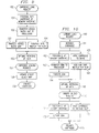
- the flow chart of FIG. 9 illustrates a cartridge load, where the tape drive is either located in an automated data storage library or is a stand alone tape drive;
- the flow chart of FIG. 10 illustrates a cartridge load, where the tape drive is located in the automated data storage library of FIG 7. in accordance with a preferred embodiment of the present invention.
- an automated data storage library 10 is illustrated.
- the invention is equally applicable to tape drives not located in libraries, and may be advantageously employed to speed the access to data, for example, by tape drives with cartridges in automated cartridge loaders.
- time to data is of greatest criticality in automated data storage libraries.
- the automated data storage library 10 is an IBM 3575 Tape Library Dataserver, which stores magnetic tape cartridges and employs 3570 tape drives.
- the library includes a plurality of tape drives 12, for example, for reading and/or writing on tape media, such as single reel or two reel magnetic tape cartridges.
- a plurality of tape media 14 are stored in banks or groups of storage slots 16.
- Tape media may encompass a variety of media, such as that contained in magnetic tape cartridges, magnetic tape cassettes, and optical tape cartridges, in various formats.
- the terms "tape media” or “media” are used herein, and any of these types of containers are referred to as “tape cartridges" or “cartridges" herein.
- the library 10 also includes a library controller 31 which comprises at least one micro-processor.
- the library controller provides the inventory of the entire library and controls the library.
- the library controller 31 comprises at least one data processor and suitable memory and data storage capability to control the operation of the library 10.
- the library controller 31 may comprise any suitable microprocessor and in the preferred embodiment this is an IBM RS/6000 processor.
- the library controller 31 controls the actions of the accessor robot 18.
- the library controller 31 is interconnected through a provided interface to one or more host processors, which provides commands requesting access to particular tape media or to media in particular storage slots.
- the host either directly, or through the library controller, controls the actions of the data storage drives 12 (through their associated controllers). Commands for access to data or to locations on the tape media and information to be recorded on, or to be read from, selected tape media are typically transmitted directly between the drives 12 and the host.
- the library controller 31 is provided with a database (not shown), which includes tables and programs, for locating the tape cartridges in the appropriate storage slots 16 and for maintaining the inventory of the tape cartridges.
- the accessor robot 18 includes servos, motors, arms (all not shown), the picker 20 with grippers, sensors and other robotic, mechanical and electrical equipment to perform functions that include (at least) the accessing and transporting of tape media between and among the storage slots 16 and the tape drives 12.
- Retrieval of data records primarily comprises the reading of the records. However, retrieval for the purpose of reading and then rewriting one or more of the records, or for writing over one or more of the records is possible. Hereinafter, although reading is emphasized, the "retrieved" records may be read and/or written.
- FIGS. 2A and 2B illustrate a single reel magnetic tape cartridge 32 having a drive hub 33 and a leader block 34.
- a memory device 35 comprising a memory circuit module 36, such as an EPROM semiconductor memory chip, mounted on board 37 is located at the edge 40 of the cartridge.
- the opposite side of board 37 comprises a plurality of conductive bars 43 and a common conductive bar 44, which provide external electrical connections to the memory circuit module 36.
- the conductive bars 43 provide a high speed electronic connection between the memory circuit module and connecting terminals, as will be explained, and the conductive bar 44 may provide a ground for preventing electrostatic discharge to the memory circuit module and may identify the orientation of the module.
- Alternative memory devices 35 may be employed in accordance with the invention, such as a rewritable magnetic chip, or other types of electronically alterable read only memory chips.
- Alternative external connections to the memory module may also be utilized, such as an LED transmitter/receiver, or other types of proximity communications.
- a two reel cartridge 50 is illustrated in FIG. 3 having drive hubs 51 and 52 for driving the tape media 53 past a tape head 54 (the tape head is in the associated tape drive).
- the cartridge has a memory device 35 comprising a memory circuit module 36 mounted on board 37.
- the board 37 is located at the edge 56 of the cartridge, and the opposite side of board 37 comprises a plurality of conductive bars which provide external electrical connections to the memory circuit module 36.
- FIG. 4 illustrates a preferred embodiment of a memory interface 60 having fixed terminals 61 and memory interface input/output circuitry 62.
- Connectors 63 provide electrical connections to the conductive bars 43 of the memory device 35 in one of the cartridges to provide a high speed electronic connection between the memory circuit module and memory interface 60.
- a connector 64 provides an electrical connection to the conductive bar 44 and may provide a ground for preventing electrostatic discharge to the memory circuit module and may identify the orientation of the module.
- the memory interface 60 is coupled to a processor by cable 66 (as will be explained) and provides a bidirectional communication with the processor.
- FIGS. 5A and 5B illustrate a preferred embodiment of a single reel tape drive 70 for use in the data storage system of the present invention.
- the tape drive 70 may be located in library 10 or may be a separate drive, as discussed above.
- Conventional elements of the tape drive include a loader 71, which is a mechanism, operated by drive servos 80, which moves a cartridge 32 into and out of the tape drive 70 in the direction of arrows 72 and either moves the cartridge vertically or moves a clutch 73 vertically in the direction of arrows 74. The vertical movement of the cartridge or the vertical movement of the clutch brings the clutch 73 into engagement with the hub 33 of the cartridge 32 (see FIG. 2A).
- a tape threader 76 engages the tape cartridge leader block 34, and, while the drive servos 80 cause a motor 81 to rotate the clutch 73 to release and unwind the tape media, drive servos operate the tape threader 76 to move the tape media along path 83 past and into engagement with "D" bearings 84 and tape head 85, and into engagement with a take-up reel 86.
- a drive controller 90 and head servos 92 operate a head servo-mechanism 93 to move the tape head 85 vertically in the directions of arrows 94 while the drive controller and drive servos 80 operate motor 81 and take-up reel 86 to move the tape media in the longitudinal direction.
- the vertical movement of head 85 brings the servo head, and therefore the data heads, into alignment.
- memory interface 60 is located in the tape drive 70 so that the loader 71 first positions the memory device 35 at the memory interface 60 by the insert motion of arrows 72. During any subsequent vertical motion of the cartridge 32, the conductive bars of the memory device 35 will maintain contact with the memory interface 60.
- memory interface 60 transfers the device block map from the memory device 35 to the controller 90.
- the controller 90 comprises a data processor and includes a memory 91.
- the controller processor may have the capability of processing the device block map. Otherwise, the controller 90 forwards the device block map over host interface 95 to a host 96 for processing.
- the host (or controller) processor then processes the device block map to order the desired host- initiated retrieval read requests into an optimal order (e.g., in accordance with the Basham et al. application).
- the tape media is threaded and the servoing of the tape head 85 is conducted to position the tape media for reading and/or writing.
- the transfer of the device block map from the memory device and the processing of the device block map occurs while the tape drive or loading mechanism positions the tape media for reading and/or writing so that the processor begins the retrieval reading process immediately upon the positioning of the tape media.
- the retrieval reading process is conducted by the controller 90 under the commands of the host 96, and the data is read and/or written by tape head 85 and decoded, etc., by data flow 97 and the data transferred directly with the host 96 over host interface 95.
- FIGS. 6A and 6B illustrate a preferred embodiment of a two reel tape drive 100 for use in the data storage system of the present invention.
- the tape drive 100 may be located in library 10 or may be a separate drive, as discussed above.
- Conventional elements of the tape drive include a loader 101, which is a mechanism, operated by drive servos 102, which moves a two reel cartridge 50 into and out of the tape drive 100 in the direction of arrows 104 and either moves the cartridge vertically or moves clutches 105 vertically in the direction of arrows 106.
- the vertical movement of the cartridge or the vertical movement of the clutch brings the clutches 105 into engagement with the hubs 51 and 52 of the cartridge 50 (see FIG. 3).
- the drive servos 102 causes a motor 108 to rotate the clutches 105 to wind and unwind the tape media to tension the tape media 53.
- Head servos 110 operate a head positioner 111 to move a tape head 112 in the direction of arrows 113 into engagement with the tape media 53.
- a drive controller 120 and head servos 110 operate a head servo-mechanism 122 to move the tape head 112 vertically in the directions of arrows 123 while the drive controller and drive servos 102 operate motor 108 to move the tape media in the longitudinal direction.
- the vertical movement of head 112 brings the servo head, and therefore the data heads, into alignment.
- memory interface 60 is located in the tape drive 100 so that the loader 101 first positions the memory device 35 at the memory interface 60 by the insert motion of arrows 104. During any subsequent vertical motion of the cartridge 50, the conductive bars of the memory device 35 will maintain contact with the memory interface 60.
- memory interface 60 transfers the device block map from the memory device 35 to the controller 120.
- the controller 120 comprises a data processor and includes a memory 125.
- the controller processor may have the capability of processing the device block map. Otherwise, the controller 120 forwards the device block map over host interface 128 to the host 96 for processing.
- the host (or controller) processor then processes the device block map to order the desired host- initiated retrieval read requests into an optimal order (e.g., in accordance with the Basham et al. application).
- the tape media is positioned with respect to the tape head 112 and the servoing of the tape head 112 is conducted to position the tape media for reading and/or writing.
- the transfer of the device block map from the memory device and the processing of the device block map occurs while the tape drive or loading mechanism positions the tape media for reading and/or writing so that the processor begins the retrieval reading process immediately upon the positioning of the tape media.
- the retrieval reading process is conducted by the controller 120 under the commands of the host 96, and the data is read and/or written by tape head 112 and decoded, etc., by data flow 129 and the data transferred directly with the host 96 over host interface 128.
- the library 10 of FIG. 1 is illustrated in block diagram form in FIG. 7.
- An embodiment of the picker 20 of accessor robot 18 is illustrated in FIG. 8.
- the picker 20 comprises gripper fingers 130 and 131 which are operated by two arms 132 and 133. The arms are pulled by spring 135 to bring the fingers 130 and 131 into engagement with the side surfaces of the cartridge 50. Similar grippers may be employed with the cartridge 32 of FIGS. 2A and 2B. A cam 138 engages follower 139 to release the cartridge after it is delivered to the tape drive 12 or storage slot 16.
- the memory interface 60 is mounted on a pivotable arm 140 so that, upon seating of the cartridge 50 in the picker 20 for transporting, the pivotable arm 140 positions the memory interface at the memory device 35 in the cartridge.
- the memory interface 60 transfers the device block map from the memory device 35 to a controller 144, which may be implemented in library controller 31.
- the controller 144 comprises a data processor and includes a memory 145.
- the controller processor may have the capability of processing the device block map. Otherwise, the controller 144 forwards the device block map over library host interface 147 to the host 96 for processing.
- the host (or controller) processor then processes the device block map to order the desired host- initiated retrieval read requests into an optimal order (e.g., in accordance with the Basham et al. application).
- the tape cartridge is transported to the tape drive 12, the cartridge is loaded and the tape media is positioned for reading and/or writing, as discussed above.
- the transfer of the device block map from the memory device and the processing of the device block map occurs while the robot accessor 18 transports the tape cartridge to the tape drive, and the tape drive loads the tape cartridge and positions the tape media for retrieval reading so that the processor begins the retrieval reading process immediately upon the positioning of the tape media.
- the reading and/or writing process is conducted by the tape drive 12 under the commands of the host 96, and the data is read and/or written by tape drive and the data is transferred directly with the host 96 over host interface 147.
- FIGS. 9 and 10 Two embodiments of a method in accordance with the present invention are illustrated in the flow charts of FIGS. 9 and 10.
- the flow chart of FIG. 9 comprises a cartridge load, whether the tape drive is located in an automated data storage library or is a stand alone tape drive.
- the tape drive may be that of FIGS. 5A and 5B for single reel cartridges or that of FIGS. 6A and 6B for two reel cartridges.
- a cartridge load request 150 is received from the host 96.
- the tape cartridge is positioned at memory interface 60.
- a processor such as the host 96, requests that the data block map be read from the memory device 35 and transferred at the memory interface to the processor in step 152.
- the processor processes the device block map for optimal file retrieval order in step 153 and the tape drive, or the loader mechanism positions the tape media for reading and/or writing in step 154.
- the processor begins the retrieval reading process immediately upon the positioning of the tape media.
- the processor Upon completion of the retrieval reading and/or writing process, the processor issues a cartridge unload request in step 157.
- the processor causes the drive to update the device block map of memory device 35 over memory interface 60, in step 158.
- the cartridge is then unloaded from the drive in step 159 and the cartridge returned to the library storage slot or a removed from the drive.
- the method of FIG. 10 relates to the preferred embodiment of the library 10 depicted in FIG. 7.
- step 160 the host 96 requests that the library load a cartridge in a specified drive 12.
- the library controller 31 operates the robot accessor 18 to retrieve the selected cartridge from its storage slot 16 in step 161.
- steps 162, 163 and 164 are conducted simultaneously with steps 165 and 166.
- Step 162 comprises picker 20 positioning the cartridge memory device 35 at the memory interface 60
- step 163 comprises the transfer of the device block map (at the request of the processor, such as host 96) from the memory device 35 to the processor, so that, in step 164, the processor processes the device block map for an optimal file retrieval order.
- the simultaneously conducted steps comprise the robot accessor 18 moving the cartridge to the selected tape drive 12 in step 165, and, in step 166, the tape drive 12 positioning the tape media for reading and/or writing.
- the processor begins the retrieval reading process immediately upon the positioning of the tape media.
- the processor Upon completion of the retrieval reading and/or writing process, the processor issues a library unload request in step 170.
- the library controller 31 operates the drive 12 to unload the cartridge and operates robot accessor 18 to retrieve the selected cartridge from the tape drive 12.
- the robot accessor 18 positions the cartridge memory device 35 at the memory interface 60, in step 171, so that the processor updates the device block map of memory device 35 over memory interface 60, in step 172.
- the robot accessor 18 under the control of the library controller 31, moves the cartridge from the tape drive 12 to a selected storage slot 16.
- the robot accessor in step 175, then delivers the cartridge to the selected library storage slot 16.
Landscapes
- Indexing, Searching, Synchronizing, And The Amount Of Synchronization Travel Of Record Carriers (AREA)
- Automatic Tape Cassette Changers (AREA)
- Management Or Editing Of Information On Record Carriers (AREA)
Applications Claiming Priority (2)
| Application Number | Priority Date | Filing Date | Title |
|---|---|---|---|
| US09/128,737 US6172833B1 (en) | 1998-08-05 | 1998-08-05 | Retrieval of serpentine pattern data using a memory device of a tape cartridge |
| US128737 | 1998-08-05 |
Publications (2)
| Publication Number | Publication Date |
|---|---|
| EP0978835A2 true EP0978835A2 (de) | 2000-02-09 |
| EP0978835A3 EP0978835A3 (de) | 2004-10-20 |
Family
ID=22436735
Family Applications (1)
| Application Number | Title | Priority Date | Filing Date |
|---|---|---|---|
| EP99306064A Ceased EP0978835A3 (de) | 1998-08-05 | 1999-07-30 | Wiederauffindung von Daten mit schlangenförmigemmuster |
Country Status (6)
| Country | Link |
|---|---|
| US (1) | US6172833B1 (de) |
| EP (1) | EP0978835A3 (de) |
| JP (1) | JP3393828B2 (de) |
| KR (1) | KR100346666B1 (de) |
| SG (1) | SG77701A1 (de) |
| TW (1) | TW418385B (de) |
Cited By (3)
| Publication number | Priority date | Publication date | Assignee | Title |
|---|---|---|---|---|
| WO2002054403A2 (en) * | 2000-12-29 | 2002-07-11 | Storage Technology Corporation | Low cost, high performance tape drive |
| GB2401237A (en) * | 2003-04-28 | 2004-11-03 | Hewlett Packard Development Co | Data transfer arrangement for disaster recovery |
| US9530123B1 (en) | 2015-10-09 | 2016-12-27 | International Business Machines Corporation | Prediction of component maintenance |
Families Citing this family (19)
| Publication number | Priority date | Publication date | Assignee | Title |
|---|---|---|---|---|
| US6571304B1 (en) * | 1999-12-06 | 2003-05-27 | International Business Machines Corporation | Control system for using memory on cartridges to overcome tape drive problems |
| JP3805157B2 (ja) * | 2000-01-19 | 2006-08-02 | 富士通株式会社 | ライブラリ装置およびテープ装置 |
| US7079346B2 (en) * | 2001-06-14 | 2006-07-18 | Hewlett-Packard Development Company, L.P. | Data storage methods and apparatus |
| US7075874B2 (en) * | 2001-07-17 | 2006-07-11 | Hewlett-Packard Development Company, L.P. | Data storage device monitoring system, method and removable data carrier use with data storage systems |
| US6958887B2 (en) * | 2002-03-28 | 2005-10-25 | Fuji Photo Film Co., Ltd. | Recording media cartridge having a memory accessible from multiple directions |
| US7080203B2 (en) * | 2003-01-21 | 2006-07-18 | International Business Machines Corporation | Serial EEPROM for volume identification and drive specific information storage in a hard disk drive library |
| US7111135B2 (en) * | 2003-06-13 | 2006-09-19 | International Business Machines Corporation | Random access time to data stored on LTO tape by incorporating stacked cartridge memory (CM) modules |
| JP4095513B2 (ja) * | 2003-09-05 | 2008-06-04 | 富士フイルム株式会社 | サーボライタおよびサーボライト方法 |
| JP2005092941A (ja) * | 2003-09-16 | 2005-04-07 | Fuji Photo Film Co Ltd | 磁気テープおよびサーボライタ |
| US7213118B2 (en) * | 2003-09-29 | 2007-05-01 | International Business Machines Corporation | Security in an automated data storage library |
| GB2406959A (en) * | 2003-10-09 | 2005-04-13 | Hewlett Packard Development Co | A data storage magazine with a memory |
| JP2005327386A (ja) * | 2004-05-14 | 2005-11-24 | Fuji Photo Film Co Ltd | 磁気記録媒体、サーボ信号書込ヘッドユニット及びサーボライタ |
| US7672753B1 (en) * | 2004-07-30 | 2010-03-02 | Symantec Operating Corporation | Optimized library device management |
| JP2006092586A (ja) * | 2004-09-21 | 2006-04-06 | Fuji Photo Film Co Ltd | サーボ信号検査装置およびサーボ信号検査方法 |
| US20070115579A1 (en) * | 2005-11-18 | 2007-05-24 | Ngo Khanh V | Method to test a tape drive |
| US20070162180A1 (en) * | 2006-01-10 | 2007-07-12 | International Business Machines Corporation | Inventory method for automated data storage library with packed cartridges |
| US8082388B2 (en) * | 2008-03-27 | 2011-12-20 | International Business Machines Corporation | Optimizing operational requests of logical volumes |
| US9021175B2 (en) | 2010-08-24 | 2015-04-28 | International Business Machines Corporation | Method for reordering access to reduce total seek time on tape media |
| CN110709933B (zh) * | 2018-04-09 | 2022-05-17 | 索尼公司 | 盒式存储器,磁带盒及记录和再现系统 |
Citations (3)
| Publication number | Priority date | Publication date | Assignee | Title |
|---|---|---|---|---|
| WO1997002566A1 (fr) * | 1995-06-30 | 1997-01-23 | Sony Corporation | Cassette, appareil enregistreur et duplicateur a bande magnetique |
| WO1997045837A1 (en) * | 1996-05-30 | 1997-12-04 | Quantum Corporation | Magnetic tape cartridge system with cartridge status memory |
| EP0851421A2 (de) * | 1996-12-25 | 1998-07-01 | Sony Corporation | Aufzeichnungs-Wiedergabegerät und -Verfahren, Eingangs-Ausgangsgerät und -Verfahren, Speichergerät, Übertragungseinrichtung sowie Informationsverarbeitungsgerät und -Verfahren |
Family Cites Families (16)
| Publication number | Priority date | Publication date | Assignee | Title |
|---|---|---|---|---|
| BE871690R (fr) * | 1978-10-27 | 1979-02-15 | Staar Sa | Dispositif de memorisation de la position instantanee d'une bande magnetique contenue dans une cassette |
| US4796110A (en) | 1986-02-18 | 1989-01-03 | Irwin Magnetic Systems, Inc. | System and method for encoding and storing digital information on magnetic tape |
| US4858039A (en) | 1988-02-04 | 1989-08-15 | Archive Corporation | Streaming tape drive with direct block addressability |
| US5438674A (en) | 1988-04-05 | 1995-08-01 | Data/Ware Development, Inc. | Optical disk system emulating magnetic tape units |
| US5485606A (en) | 1989-07-10 | 1996-01-16 | Conner Peripherals, Inc. | System and method for storing and retrieving files for archival purposes |
| DK385489D0 (da) | 1989-08-07 | 1989-08-07 | Bang & Olufsen As | Optage- og gengivesystem, navnlig videosystem, med baandkassetter |
| US5121270A (en) | 1989-09-19 | 1992-06-09 | Alcudia Ezra R | Multitransducer head positioning servo for use in a bi-directional magnetic tape system |
| US5373485A (en) | 1991-09-03 | 1994-12-13 | Minnesota Mining And Manufacturing Company | Method for locating data in a data cartridge system |
| US5369532A (en) | 1991-11-12 | 1994-11-29 | Storage Technology Corporation | Method and apparatus for managing data on rewritable media to define read/write operational status |
| US5613082A (en) | 1993-06-14 | 1997-03-18 | International Business Machines Corporation | Control of record media using device only accessible control areas and directory of media control marks and error history |
| JPH07114443A (ja) | 1993-10-15 | 1995-05-02 | Toshiba Corp | ファイル検索方法及び磁気テープ装置 |
| US5485321A (en) | 1993-12-29 | 1996-01-16 | Storage Technology Corporation | Format and method for recording optimization |
| US5867335A (en) * | 1994-09-02 | 1999-02-02 | Sony Corporation | Autochanger |
| EP0708444A1 (de) | 1994-10-21 | 1996-04-24 | Hewlett-Packard Company | Gerät zum Zugriff auf ein Band mit linearer, schlangenförmiger Spur |
| US5717951A (en) | 1995-08-07 | 1998-02-10 | Yabumoto; Kan W. | Method for storing and retrieving information on a magnetic storage medium via data blocks of variable sizes |
| US5757571A (en) * | 1996-03-12 | 1998-05-26 | International Business Machines Corporation | Flexible-capacity scaling for efficient access of ordered data stored on magnetic tape media |
-
1998
- 1998-08-05 US US09/128,737 patent/US6172833B1/en not_active Expired - Fee Related
-
1999
- 1999-02-08 TW TW088101887A patent/TW418385B/zh not_active IP Right Cessation
- 1999-07-08 JP JP19406499A patent/JP3393828B2/ja not_active Expired - Fee Related
- 1999-07-13 KR KR1019990028265A patent/KR100346666B1/ko not_active IP Right Cessation
- 1999-07-29 SG SG1999003663A patent/SG77701A1/en unknown
- 1999-07-30 EP EP99306064A patent/EP0978835A3/de not_active Ceased
Patent Citations (3)
| Publication number | Priority date | Publication date | Assignee | Title |
|---|---|---|---|---|
| WO1997002566A1 (fr) * | 1995-06-30 | 1997-01-23 | Sony Corporation | Cassette, appareil enregistreur et duplicateur a bande magnetique |
| WO1997045837A1 (en) * | 1996-05-30 | 1997-12-04 | Quantum Corporation | Magnetic tape cartridge system with cartridge status memory |
| EP0851421A2 (de) * | 1996-12-25 | 1998-07-01 | Sony Corporation | Aufzeichnungs-Wiedergabegerät und -Verfahren, Eingangs-Ausgangsgerät und -Verfahren, Speichergerät, Übertragungseinrichtung sowie Informationsverarbeitungsgerät und -Verfahren |
Non-Patent Citations (3)
| Title |
|---|
| HP, IBM, SEAGATE: "Linear Tape - Open (LTO) Technology White Paper" INTERNET ARTICLE, [Online] April 1998 (1998-04), pages 1-9, XP002293942 Retrieved from the Internet: URL:http://www.storageheaven.com/downloads/ultrium.pdf> [retrieved on 2004-08-25] * |
| ROGER POZAK: "Tape Drive Technology Comparison : Sony AIT . Exabyte Mammoth . Quantum DLT" INTERNET ARTICLE, [Online] April 1999 (1999-04), XP002293944 Retrieved from the Internet: URL:www.qualstar.com/tapetechcomp.pdf> [retrieved on 2004-08-25] * |
| W E WILLIAMS: "DLT technology overview : A survey of general technology and design features" IIE, [Online] 27 December 1996 (1996-12-27), XP002293943 Retrieved from the Internet: URL:http://ieeexplore.ieee.org/iel3/4720/13144/00603015.pdf?isNumber=13144&prod=STD&arnumber=603015&arSt=5%2F1&ared=5%2F5&arAuthor=Williams%2C+W.E.> [retrieved on 2004-08-25] * |
Cited By (6)
| Publication number | Priority date | Publication date | Assignee | Title |
|---|---|---|---|---|
| WO2002054403A2 (en) * | 2000-12-29 | 2002-07-11 | Storage Technology Corporation | Low cost, high performance tape drive |
| WO2002054403A3 (en) * | 2000-12-29 | 2003-12-24 | Storage Technology Corp | Low cost, high performance tape drive |
| GB2401237A (en) * | 2003-04-28 | 2004-11-03 | Hewlett Packard Development Co | Data transfer arrangement for disaster recovery |
| US8549237B2 (en) | 2003-04-28 | 2013-10-01 | Hewlett-Packard Development Company, L.P. | Method and apparatus for use in data transfer |
| US9530123B1 (en) | 2015-10-09 | 2016-12-27 | International Business Machines Corporation | Prediction of component maintenance |
| US9601155B1 (en) | 2015-10-09 | 2017-03-21 | International Business Machines Corporation | Prediction of component maintenance |
Also Published As
| Publication number | Publication date |
|---|---|
| SG77701A1 (en) | 2001-01-16 |
| KR100346666B1 (ko) | 2002-07-31 |
| JP2000067563A (ja) | 2000-03-03 |
| KR20000016927A (ko) | 2000-03-25 |
| JP3393828B2 (ja) | 2003-04-07 |
| TW418385B (en) | 2001-01-11 |
| EP0978835A3 (de) | 2004-10-20 |
| US6172833B1 (en) | 2001-01-09 |
Similar Documents
| Publication | Publication Date | Title |
|---|---|---|
| US6172833B1 (en) | Retrieval of serpentine pattern data using a memory device of a tape cartridge | |
| US5970030A (en) | Automated data storage library component exchange using media accessor | |
| US5883864A (en) | Media library having locally vectored drive addressing | |
| US7136720B2 (en) | Disk cartridge data storage methods and apparatus | |
| US7450331B2 (en) | Variable mobile media storage system | |
| US6338006B1 (en) | Data storage library with efficient cartridge eject | |
| US5819309A (en) | Automated tape cartridge library with accelerated calibration | |
| US5956301A (en) | Automated data storage library media handling with a plurality of pickers having multiple grippers | |
| US8166240B2 (en) | Method for inventory of an automated data storage library | |
| US7505224B2 (en) | Management of data cartridges in multiple-cartridge cells in an automated data storage library | |
| US5570337A (en) | Modular independent libraries interconnected by a common media exchange and input apparatus | |
| EP0620552A2 (de) | Automatische Datenspeicherungsbibliothek | |
| US20120300342A1 (en) | Efficient moves via repository | |
| US20150050106A1 (en) | Efficient moves via repository | |
| US6480905B1 (en) | Data storage library with efficient cartridge insert | |
| US6985328B2 (en) | One and three quarters inch form factor tape cartridge autoloader | |
| US10929070B2 (en) | Reduced data access time on tape with data redundancy | |
| US20120127607A1 (en) | Efficient moves via repository | |
| US7518822B1 (en) | Data storage cartridge gripper with deep-reach | |
| WO1997029484A2 (en) | Automated tape cartridge library | |
| US5325249A (en) | Differentiation of media types via leader block characteristics | |
| JP3443802B2 (ja) | ライブラリ装置 | |
| US20040081539A1 (en) | Three and one-half inch form factor tape cartridge autoloader | |
| JPH0612836A (ja) | 電源切断制御方式 | |
| JPH10214481A (ja) | ライブラリ装置 |
Legal Events
| Date | Code | Title | Description |
|---|---|---|---|
| PUAI | Public reference made under article 153(3) epc to a published international application that has entered the european phase |
Free format text: ORIGINAL CODE: 0009012 |
|
| AK | Designated contracting states |
Kind code of ref document: A2 Designated state(s): AT BE CH CY DE DK ES FI FR GB GR IE IT LI LU MC NL PT SE |
|
| AX | Request for extension of the european patent |
Free format text: AL;LT;LV;MK;RO;SI |
|
| PUAL | Search report despatched |
Free format text: ORIGINAL CODE: 0009013 |
|
| AK | Designated contracting states |
Kind code of ref document: A3 Designated state(s): AT BE CH CY DE DK ES FI FR GB GR IE IT LI LU MC NL PT SE |
|
| AX | Request for extension of the european patent |
Extension state: AL LT LV MK RO SI |
|
| 17P | Request for examination filed |
Effective date: 20041112 |
|
| AKX | Designation fees paid |
Designated state(s): AT BE CH CY DE DK ES FI FR GB GR IE IT LI LU MC NL PT SE |
|
| STAA | Information on the status of an ep patent application or granted ep patent |
Free format text: STATUS: THE APPLICATION HAS BEEN REFUSED |
|
| 18R | Application refused |
Effective date: 20090312 |