EP0978686B1 - Meche de combustion d'une chambre de combustion de combustible liquide - Google Patents
Meche de combustion d'une chambre de combustion de combustible liquide Download PDFInfo
- Publication number
- EP0978686B1 EP0978686B1 EP99900677A EP99900677A EP0978686B1 EP 0978686 B1 EP0978686 B1 EP 0978686B1 EP 99900677 A EP99900677 A EP 99900677A EP 99900677 A EP99900677 A EP 99900677A EP 0978686 B1 EP0978686 B1 EP 0978686B1
- Authority
- EP
- European Patent Office
- Prior art keywords
- wick
- flame
- skin layer
- liquid fuel
- igniter
- Prior art date
- Legal status (The legal status is an assumption and is not a legal conclusion. Google has not performed a legal analysis and makes no representation as to the accuracy of the status listed.)
- Expired - Lifetime
Links
Images


Classifications
-
- F—MECHANICAL ENGINEERING; LIGHTING; HEATING; WEAPONS; BLASTING
- F21—LIGHTING
- F21V—FUNCTIONAL FEATURES OR DETAILS OF LIGHTING DEVICES OR SYSTEMS THEREOF; STRUCTURAL COMBINATIONS OF LIGHTING DEVICES WITH OTHER ARTICLES, NOT OTHERWISE PROVIDED FOR
- F21V37/00—Details of lighting devices employing combustion as light source, not otherwise provided for
- F21V37/0004—Details of lighting devices employing combustion as light source, not otherwise provided for using liquid fuel
- F21V37/002—Wicks
-
- F—MECHANICAL ENGINEERING; LIGHTING; HEATING; WEAPONS; BLASTING
- F23—COMBUSTION APPARATUS; COMBUSTION PROCESSES
- F23D—BURNERS
- F23D3/00—Burners using capillary action
- F23D3/02—Wick burners
- F23D3/08—Wick burners characterised by shape, construction, or material, of wick
-
- F—MECHANICAL ENGINEERING; LIGHTING; HEATING; WEAPONS; BLASTING
- F23—COMBUSTION APPARATUS; COMBUSTION PROCESSES
- F23D—BURNERS
- F23D3/00—Burners using capillary action
- F23D3/02—Wick burners
- F23D3/18—Details of wick burners
-
- F—MECHANICAL ENGINEERING; LIGHTING; HEATING; WEAPONS; BLASTING
- F23—COMBUSTION APPARATUS; COMBUSTION PROCESSES
- F23D—BURNERS
- F23D3/00—Burners using capillary action
- F23D3/40—Burners using capillary action the capillary action taking place in one or more rigid porous bodies
-
- F—MECHANICAL ENGINEERING; LIGHTING; HEATING; WEAPONS; BLASTING
- F23—COMBUSTION APPARATUS; COMBUSTION PROCESSES
- F23Q—IGNITION; EXTINGUISHING-DEVICES
- F23Q2/00—Lighters containing fuel, e.g. for cigarettes
- F23Q2/34—Component parts or accessories
- F23Q2/44—Wicks; Wick guides or fastenings
Definitions
- This invention relates to a wick that, in a cigarette lighter, fire-lighting device or other burner using a liquid fuel composed mainly of alcohol, utilizes capillary attraction to draw up from a fuel tank liquid fuel to be burned, particularly to the structure of the flame-producing section where combustion is conducted.
- An alcohol fuel such as ethyl alcohol, a benzine fuel of the petroleum benzin type including gasoline or a liquid gas fuel such as butane gas or propane gas is generally used as the fuel of a cigarette lighter, fire-lighting device, torch, lamp or other such burner.
- benzine fuel that is a mixture of petroleum benzin-type hydrocarbon compounds
- the fuel is a mixture of compounds with different boiling points.
- volatilization of the components begins with the low-boiling-point benzine components and then progressively shifts to hydrocarbons with higher boiling points. Since the composition of the fuel remaining in the burner therefore varies over the burning period, the flame length changes.
- gasoline As benzine and gasoline have high volatility, burners that use them require a sealed structure for reducing evaporation from the fuel storage section and the wick portion. If the sealing is insufficient, fuel is lost through evaporation and the frequency of bothersome fuel refills increases. In addition, benzine and gasoline have distinctive odors which may be found disagreeable.
- the gas pressure is high in the use temperature range of the burner and the vessel storing the fuel has to have a pressure-resistant structure.
- the flame length changes with variation in the gas pressure and since it is a characteristic of the gas pressure to vary logarithmically and greatly with temperature, large change in flame length with temperature becomes a particular problem.
- the fuel supply system of the burner requires a special design countermeasure for effecting temperature compensation, which complicates the structure and is disadvantageous from the aspect of cost.
- a liquid fuel composed mainly of alcohol e.g., a lower monovalent alcohol such as ethyl alcohol, methyl alcohol or propyl alcohol
- a liquid fuel composed mainly of alcohol, e.g., a lower monovalent alcohol such as ethyl alcohol, methyl alcohol or propyl alcohol
- the fuel storage section therefore does not require a pressure-resistant vessel and the sealing structure for sealing the fuel tank and the wick need only be capable of preventing alcohol evaporation. This is advantageous from the point of simplifying the structure and lowering the cost of the burner.
- the means used to supply the liquid fuel from the fuel storage section to the flame-producing section is generally a wick that utilizes the surface tension of the liquid fuel to draw it up through continuous fine holes or fine voids among bundled thin fibers by capillarity and burns it at the tip portion thereof.
- the wick used for drawing up the fuel is a string-like one obtained by twisting fibers, one obtained by bundling glass fibers, one using both of these with the glass fibers enclosed in cotton yarn and the result wound with fine metal wires to prevent disintegration, or the like, whose lower draw-up section functions to draw up fuel to be burned at the upper flame-producing section.
- the initial flame length after lighting, the change in flame length, the saturated flame length, the flame thickness and the like differ depending on the material and shape of the wick.
- the burner must therefore be configured to satisfy the desired characteristics for the use mode.
- a flame is formed by burning of gas produced by liquid fuel volatilizing from the tip end surface and the tip peripheral portion of the flame-producing section.
- liquid fuel further volatizes and rises from the lower peripheral portion of the flame-producing section and is then lit, a still thicker and longer flame is formed.
- This burning condition is similar to the shape of a flame produced by lighting a candle.
- a wick for obtaining the required flame length taking continuous combustion into consideration, it is necessary to give the wick a certain degree of thickness, i.e., largeness of the tip end surface. However, a proportional relationship exits between the thickness of the wick and the thickness of the flame, so that the flame is thicker with a thicker wick.
- volatized liquid fuel in order to light a wick of the foregoing type, it is necessary for volatized liquid fuel to be present in the vicinity of the portion of the wick acted on by sparks produced by a flint or electric discharge. It has been found that, in addition to the volatization of fuel from the upper end surface of the wick, it is also important from the aspect of securing igniting performance that fuel volatized from the wick side surface also be present, particularly that it greatly affects the lighting success rate at low temperatures.
- the igniting performance is better when the igniter for causing sparks to fly toward the wick is installed closer to the wick, when the flame is thick, the edge of the flame comes close to the igniter to raise the temperature of the igniter (e.g., a striker wheel). If the striker wheel should be heated, the heat may, for example, be conducted to its plastic support portion to melt the support portion. The striker wheel may then be detached by the pressing force of the flint urged against the striker wheel, making it useless. In particular, when the wick and the igniter are near each other, the flow of air around the wick changes and the flame tends to swell toward the igniter side. This may cause the aforesaid problem of overheating.
- the igniter e.g., a striker wheel
- the flame may be hard to see even if a material exhibiting a flame coloring reaction is added to the fuel. A need is therefore also felt for further coloring the flame to increase the clarity of the flame shape.
- JP 55 075106 A shows a gasification wick comprising an exterior tar-permeation preventing material between a gasification portion thereof and a fuel-wetted portion thereof, whereby the permeation of tar into an inner portion of the gasification wick and a decrease in the fuel sucking performance thereof can be prevented. Furthermore, at least a side surface not including an upper end surface of the flame-producing section of the wick is provided with a skin layer for suppressing volatization of liquid fuel.
- DE 43 27 437 A discloses a wick for a liquid fuel burner wherein a thin metal ring is placed around the top end of the wick, thereby suppressing fuel volatization through the side surface of the wick.
- the present invention is aimed at providing a wick for a liquid fuel burner that makes it possible to obtain a flame shape suitable to the purpose of use, particularly a thin and long flame.
- the invention liquid fuel burner wick which overcomes the problems set out in the foregoing, has liquid fuel impregnated in stuffing accommodated in a fuel tank and comprising a wick with a draw-up section in contact with the stuffing for drawing up liquid fuel by capillarity and burning it at a tip flame-producing section and an igniter for lighting the flame-producing section, the wick is constituted of a porous material and at least a side surface not including an upper end surface of the flame-producing section is provided with a skin layer for suppressing volatization of liquid fuel, wherein the wick liquid fuel volatization suppressing action at a side surface on the side of the igniter is smaller than volatization suppressing action at other side surface.
- the liquid fuel volatization suppressing action of the side surface on the side of the igniter can be made smaller than that of other side surfaces by slit-wise removing the skin layer to form it partially or by not forming the skin layer.
- the skin layer can be formed of a material having no permeability whatsoever with respect to the liquid fuel.
- the skin layer throughout or partially on the wick side surfaces, it is preferable to provide the skin layer as a porous coating having lower liquid fuel permeability than the permeability at the wick interior so as to enable liquid fuel to permeate to and volatize from the surface.
- the skin layer is constituted, for example, by application of or immersion in what is obtained by mixing a metal oxide powder and a binder, and solidification by drying. Otherwise the skin layer is constituted by application of or immersion in what is obtained by mixing a heat-resistant inorganic compound powder, a metal powder or a mixture thereof and a binder, and solidification by drying.
- the metal oxide powder is used titanium oxide, aluminum oxide or the like, individually or as mixed.
- the binder it is preferable to use a waterglass material such as sodium silicate or potassium silicate or a low-melting-point glass material.
- the skin layer is preferably provided to a thickness of 0.2mm-0.5mm.
- the skin layer can be constituted by application of or immersion in a heat-resistant paint, and drying.
- the skin layer preferably contains a metal compound exhibiting a flame coloring reaction.
- the skin layer can be added with carbon. After the skin layer has been formed, it can be applied with a coating solution containing carbon.
- the liquid fuel permeability of the skin layer can be made to differ between the upper end and other portions of the flame-producing section.
- it can be provided so that its permeability is high at the upper end and low at the lower end, or vice versa. In this case, it suffices to provide the skin layer to differ in thickness between the upper end and other portions of the flame-producing section.
- the tip end surface of the wick provided with the skin layer can be formed as an inclined surface and the inclined surface be disposed to face the igniter.
- the wick is preferably formed of a heat-resistant material such as ceramic fiber or glass fiber to have a bar-like shape of rectangular cross-section, but can also be formed of a porous ceramic or porous glass material. Moreover, the wick can also be constituted of a porous material compression-formed in a direction perpendicular to the axial direction thereof.
- a surface compressed during compression-forming can be disposed to face the igniter for the purpose of preventing overheating of the igniter in the case where the formation of the skin layer makes the overall amount of volatization from the side surfaces large.
- a surface perpendicular to a surface compressed during compression-forming can be disposed to face the igniter so as to enhance the lighting success rate in the case where the formation of the skin layer makes the overall amount of volatization from the side surfaces small.
- the length of the flame is maintained while simultaneously reducing its thickness because the volatization of liquid fuel from the side surfaces of the flame-producing section is, by formation of the skin layer, controlled to be suppressed to a degree enabling ignition.
- the liquid fuel in the case of a wick having the sides of its flame-producing section completely covered and sealed by a skin layer with no permeability with respect to the liquid fuel, i.e., one with absolutely no volatization of fuel from its side surfaces, the liquid fuel produces a flame only by the fuel volatization from the upper end surface of the wick and the flame is therefore narrow.
- a wick is usually lit from a side surface, lighting becomes difficult in the case of a wick that produces no liquid fuel volatization at such a side surface.
- the wick enables lighting from a side surface by scattering sparks and, moreover, so as not to make the flame thickness large, is either formed with a porous skin layer that permits permeation and volatization of liquid fuel from the side surfaces of the flame-producing section of the wick to a degree enabling ignition or is made so that the volatization suppressing action of the side surface on the side of the igniter is smaller than that of the other side surfaces, thereby enabling good ignition by the igniter, while drawing up liquid fuel to the upper end surface of the wick and exposing it at a surface of the wick material having high volatization performance, thereby producing a long and thin flame and enabling ordinary lighting.
- liquid fuel composed mainly of alcohol there can, for example, be used one having a lower monovalent alcohol, namely, methyl alcohol, ethyl alcohol or propyl alcohol, as its main component and having mixed therewith a saturated hydrocarbon such as hexane or heptane for coloring the flame.
- a lower monovalent alcohol namely, methyl alcohol, ethyl alcohol or propyl alcohol
- a saturated hydrocarbon such as hexane or heptane for coloring the flame.
- a wick for a liquid fuel burner such as the foregoing, by constituting the wick of a porous material and providing the skin layer to suppress volatization of liquid fuel from the wick side surfaces on at least a wick side surface not including the upper end surface, good igniting performance can be secured from the igniter side owing to the fuel volatized from the side surface on the side of the igniter.
- the upper end surface of the wick can be given some degree of magnitude so that the desired flame length is ensured by sufficient fuel volatization from the upper end surface, while the skin layer, by suppressing the amount of fuel volatization from the side surfaces, enables the thickness of the flame, particularly the thickness of its lower end, to be prevented from enlarging, so as to keep the flame thin and prevent temperature rise of the igniter caused by the flame approaching the igniter, and a flame of a thin and long shape not obtainable in the past can be obtained with a simple structure.
- this increases the degree of freedom regarding flame shape, it becomes possible to secure characteristics matched to the purpose of use of, for example, a cigarette lighter, fire-lighting device or other such burner, and thereby increase its commercial value.
- the objective of making it easy to secure a volatization amount for lighting and the objective of thinning the flame thickness by suppressing volatization at the other side surfaces can both be readily achieved at the same time.
- forming a skin layer such as described in the foregoing heightens the hardness of the flame-producing section of the wick, thereby increasing its strength, and prolongs the service life of the flame-producing section with respect to use.
- time-course change in the flame during continuous burning after lighting is such that the growth in the flame length immediately after lighting rises rapidly and the saturated flame length is short, so that burning characteristics ideal for a fire-lighting device or the like are obtained.
- the flame is formed mainly by burning fuel volatized from the upper end surface of the flame-producing section of the wick and is not dependent on the amount of volatization from the side surfaces of the flame-producing section.
- the amount of projection of the flame-producing section of the wick from the wick holder can therefore by shortened, which makes it easer to design a closure cap for covering the flame-producing section to prevent volatization.
- volatization of fuel from the side surfaces of a flame-producing section of the foregoing description is controlled by forming the skin layer so as to form a thin and long flame, fuel consumption is reduced in comparison with burning that produces a thick flame of the same length and, therefore, the number of uses and the use time are greatly increased for the same amount of fuel.
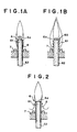
- Figure 1A shows the basic structure of the wick of the present invention.
- the main body of the wick 6 is formed of a porous material.
- the portion projecting upward from a wick holder 7 is formed as flame-producing section 61 and a portion below the wick holder 7 that makes contact with stuffing 3 (see Figure 3) impregnated with and retaining liquid fuel is formed as a draw-up section 62.
- the skin layer 8 is, for example, formed porous so as to have permeability enabling liquid fuel drawn up through the wick interior by capillarity to pass to the surface and volatize and so that the permeability thereof is lower than the permeability of the main body material at the wick interior.
- the wick 6 is formed in, for instance, bar shape of a porous material having internal capillary passages, such as ceramic fiber, acrylic fiber, glass fiber, porous ceramic or porous glass material and the outer periphery from the flame-producing section 61 thereof to the portion retained by the wick holder 7 is formed with the skin layer 8 to a thickness of 0.2-0.5mm by application of or immersion in, and drying, of a heat-resistant paint or a coating solution obtained by mixing a metal oxide powder such as of titanium oxide or aluminum oxide, a heat-resistant inorganic compound powder, a metal powder or the like with a binder composed of a waterglass material such as sodium silicate or potassium silicate or a low-melting-point glass material.
- a porous material having internal capillary passages such as ceramic fiber, acrylic fiber, glass fiber, porous ceramic or porous glass material
- the outer periphery from the flame-producing section 61 thereof to the portion retained by the wick holder 7 is formed with the skin layer 8 to a thickness of
- the upper end surface 6a of the flame-producing section 61 is not applied with the coating solution or the tip end surface thereof is cut off after coating, so as to expose the wick material surface of the aforesaid ceramic fiber or the like.
- the relationship between the igniting performance and the flame thickness can be adjusted by adjusting the coating thickness of the coating solution.
- the upper end surface 6a can be formed to be inclined.
- Figure 1B shows the burning condition of a wick 60 that is a comparative example not formed with a skin layer.
- a large amount of fuel is volatilized as indicated by the arrows.
- the flame formed by lighting and burning of this fuel volatized at the side surfaces joins with the flame produced by the volatized gas from the upper end surface 6a to form a thick and large flame overall.
- the flame is particularly thick at the lower end.
- the temperature rise caused by continuous burning after lighting increases the amount of volatization from the upper end surface 6a and the peripheral surfaces, so that the flame enlarges to assume a saturated state like that illustrated.
- the projection length of the flame-producing section 61 from the wick holder 7 can be about 3mm, which is shorter than one not formed with the skin layer.
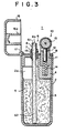
- Figure 2 shows the burning when the skin layer 8 is formed thick to further lower the fuel permeability of the side surfaces of the flame-producing section 61.
- the temperature rise occurring simultaneously with flame formation after lighting of the flame-producing section 61 generates an updraft at the side surfaces of the flame-producing section 61.
- the fuel gas volatized from the skin layer 8 therefore rises without forming a flame at the side surfaces and burns after merging with the flame produced by the fuel gas volatized from the upper end surface 6a of the flame-producing section 61.
- the thickness of the lower end of the flame becomes still thinner.
- the thickness and length of the flame can be determined to match the purpose of use of the burner.
- the skin layer 8 can be partially or totally removed on the side surface on the ignition side so as to reduce the volatization suppressing action and increase the amount of volatization for lighting.
- the flame shape can be further varied by making the permeability of the skin layer 8 high at the upper end and low at the lower portion, or vice versa, such as by making the coating thickness different.
- the amount of volatization by permeation through the skin layer 8 must be an amount sufficient to ensure igniting performance, the required amount varies with, for example, the igniting performance of the igniter.
- a metal compound exhibiting a flame coloring reaction or carbon is added to the skin layer 8 or the skin layer 8 is coated with a paint mixed with carbon.
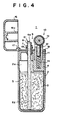
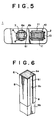
- Figure 3 shows a schematic sectional view of the structure of a cigarette lighter as an example of a liquid fuel burner incorporating a wick 6 of the foregoing type. It also shows a specific example of the wick 6.
- a lighter 1 has a fuel tank 2 of cylindrical shape with closed bottom. Stuffing 3 composed of a fiber material is inserted into the interior of the fuel tank 2 to be impregnated with and retain liquid fuel. A top cover 4 is fixed to the upper portion of the fuel tank 2 to constitute a fuel reservoir section 5 for storing liquid fuel. The stuffing 3 is charged into the fuel tank 2 from the bottom side to leave an upper space 2a.
- the fuel tank 2 is, for example, provided as a shaped article made of polypropylene with an inner volume of 5cm 3 .
- the stuffing 3 is polypropylene fiber of a thickness of 6 denier compacted in the fuel tank 2 to a density of 0.05g/cm 3 . 4g of liquid fuel, a mixture of 95wt% ethyl alcohol and 5wt% n-hexane, is poured and impregnated into this stuffing 3 for storage therein.
- a metal wick holder 7 is fixed to the top cover 4 as passed vertically therethrough into the fuel tank 2.
- the bar-shaped wick 6 is inserted vertically into the wick holder 7.
- the wick 6 is formed integrally of the same material at the flame-producing section 61, i.e., the tip end projecting upward from the wick holder 7, and at a lower draw-up section 62 in contact with the stuffing 3.
- the wick 6 is formed of ceramic fiber by, for example, adding a small amount of organic binder and curing agent to 2.8 ⁇ m-thick ceramic fibers obtained by fiberizing a raw material composed mainly of alumina and silica, forming the fibers into a plate having a fiber packing density of 0.16g/cm 3 , cutting a 70mm-long bar of 3mmx4mm rectangular cross-section from the plate and inserting the bar in the wick holder 7 of an inner diameter of 5.0mm ⁇ , an outer diameter of 6.0mm ⁇ and a length of 7.0mm.
- the flame-producing section 61 of the wick 6 is fixed so that its projection length from the upper end surface of the wick holder 7 is 3mm and that its draw-up section 62 is inserted into the stuffing 3 to a length of 45mm from the lower end.
- At least the side surfaces of the flame-producing section 61 of the wick 6 are covered by a skin layer 8 that is porous and has a lower liquid fuel permeability than the internal material.
- the skin layer 8 is formed on the side surfaces to a prescribed length (e.g., 10mm) from the upper end of the wick 6, with the ceramic fiber surfaces of the upper end surface 6a and the side surfaces of the draw-up section 62 being left exposed.
- the skin layer 8 in the present embodiment is formed by preparing a coating solution obtained by mixing 50wt% of sodium silicate + 50wt% of water and mixing the result with titanium dioxide at a mixing ratio of 70wt% to 30wt%, applying this coating solution to a thickness after drying of 0.3mm, and then drying it.
- Such a wick 6 draws up the liquid fuel impregnated in the stuffing 3 by its draw-up section 62 utilizing capillarity.
- the drawn-up liquid fuel is supplied to the flame-producing section 61 and the flame-producing section 61 projecting upward from the wick holder 7 is lit to burn and generate a flame.
- the wick 6 can have its flame-producing section 61 and its fuel draw-up section 62 formed of different materials.
- the flame-producing section 61 is formed of the aforesaid ceramic fiber and the draw-up section 62 is formed of, for example, acrylic fiber and the two are joined in contact.
- This draw-up section 62 is formed by adding a binder and a curing agent to acrylic fibers of a fiber thickness of 3 denier and bundling them into a rod to have a void ratio after bonding and shaping of 60% and an outer diameter of 3.4mm ⁇ .
- An igniter 10 is installed on the top cover 4 to face the tip of the flame-producing section 61.
- a bracket 11 of the igniter 10 fixed to the top cover 4 has a flint 12 inserted therein to be vertically movable and a rotating striker wheel 13 is provided on an upper cover of the bracket 11.
- the tip of the flint 12 is pressed onto the peripheral surface of the rotating striker wheel 13 by the energizing force of a flint pusher spring 14 and rotation of the rotating striker wheel 13 causes sparks to fly toward the wick 6.
- a closure cap 16 for evaporation prevention is provided to openably/closably cover the flame-producing section 61 together with the protruding portion of the wick holder 7.
- This closure cap 16 is rotatably pivoted by a pin 17 at one end portion of the upper surface of the top cover 4 of the fuel tank 2.
- an inner cover 16a for enclosing the outer periphery of the wick holder 7 and covering/sealing the tip of the flame-producing section 61.
- An O-ring 19 is horizontally attached to the outer peripheral root portion of the wick holder 7 and the inner peripheral surface of the inner cover 16a presses thereon to enhance the sealing property.
- a face plate 18 is provided on the upper surface of the top cover 4.
- the gaps formed between the round inner surface of the wick holder 7 and the peripheral surfaces of the flame-producing section 61 of rectangular cross-section function as air passages that communicate the interior of the fuel tank 2 with the upper space 2a.
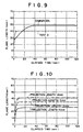
- the cigarette lighter 1 of Figure 3 was used and the change in flame length during continuous burning after lighting was measured.
- the flame length immediately after lighting was 18mm, grew quickly to 35mm at 5 seconds, and then assumed a saturated state of equilibrium with a flame length of 38mm at 10 seconds (see Test 1 in Figure 8).
- the maximum thickness of the flame was 7mm.
- the flame in the burning condition after passage of a certain time period following lighting exhibited orange coloration owing to a flame coloring reaction of the sodium silicate in the skin layer 8. There was thus obtained a thin and long flame shape satisfying the burning conditions required of a cigarette lighter.
- a similar skin layer could also be formed when aluminum oxide powder (alumina powder) was incorporated instead of the titanium dioxide.
- a similar skin layer could also be formed when potassium silicate was incorporated instead of the sodium silicate.
- a different material is used to form the skin layer 8 in this embodiment.
- low-melting-point glass glass frit
- the binder bonding agent
- it is formed like that of the first embodiment.
- the skin layer 8 of this embodiment is formed by preparing a coating solution obtained by mixing 80wt% of glass frit and 20wt% of titanium dioxide and mixing the result at a mixing ratio of 1 : 1 with a 5% solution of polyvinyl alcohol as binder, applying this coating solution to the outer periphery of the flame-producing section 61 of the wick 6 over a length of the side surfaces of 10mm from the upper end surface (thickness: 0.3mm) and, after drying, sintering it at 800°C x 10min (temperature increase rate: 10°C/min).
- the composition of the glass frit of the foregoing example is SiO 2 : 10%, ZnO : 65% and B 2 O 3 : 25%.
- the lighter of this embodiment was used and the change in flame length after lighting was measured.
- the flame length immediately after lighting was 20mm and then grew to 40mm at 5 seconds, in which condition it assumed a saturated state of equilibrium.
- the maximum thickness of the flame was 7mm.
- a thin and long flame shape like that of the first embodiment was obtained.
- the surface of the skin layer 8 of a wick 6 formed in the same manner as that of the first embodiment is further formed with a coating layer.
- the skin layer 8 is constituted by applying and drying a coat of an oil ink containing carbon on a coated surface applied with a coating solution obtained by mixing 70wt% of a mixture of 50wt% of sodium silicate + 50wt% of water with 30wt% of titanium dioxide.
- the lighter was used and the change in flame length after lighting was measured.
- the results obtained for the change in flame length and flame thickness after lighting were the same as in the first embodiment.
- a further orange coloration of the flame was exhibited because of the flame coloring effect of the carbon.
- the upper end surface 6a of the wick 6 provided with the skin layer 8 is formed as an inclined surface and the inclined upper end surface 6a is disposed to face the igniter 10.
- This embodiment in which the wick 6 is similar to that of the first embodiment, relates to the porous material at the interior of the wick 6, namely, the material density of some of the surfaces is high.
- the wick 6 is formed of ceramic fiber of the type mentioned earlier, this ceramic fiber is added with a small amount of organic binder and curing agent and compressed into a plate, which is cut to form a 70mm-long bar of 3mmx4mm rectangular cross-section, and a skin layer 8 is similarly formed on the side surfaces of the flame-producing section 61.
- the wick 6 fabricated in the foregoing manner is compression-formed in a direction perpendicular to its axial direction (longitudinal direction).
- the compressed surfaces surfaces that received pressing force during the compression
- the liquid fuel volatization suppressing action at a side surface 6b on the igniter 10 side of the wick 6 formed with the skin layer 8 is made smaller than the volatization suppressing action of the other side surfaces.
- FIG. 5 is a plan view showing a lighter 1 equipped with the wick 6 of this embodiment, with the closure cap 16 removed.
- the wick 6 is made of ceramic fiber, has a 3mmx4mm rectangular cross-section, is 70mm in length, and has its three side surfaces other than the side surface 6b on the side of the igniter 10 formed with the skin layer 8 over a length of 10mm from the upper end surface 6a thereof.
- the skin layer 8 is constituted by applying and drying a coating solution obtained by mixing sodium silicate and titanium dioxide at a mixing ratio of 70wt% to 30wt%, to a thickness of 0.3mm, and not applying the skin layer 8 to the upper end surface 6a of the wick 6 and the side surface 6b thereof on the side of the igniter 10 but leaving the internal material exposed.
- the wick 6 is inserted into and fixed in the wick holder 7 so that the projection length is 3mm. Other aspects are like those of the first embodiment.
- the thickness of the flame in the burning condition of the lighter 1 of this embodiment was somewhat swollen toward the side of the igniter but a flame that was of thin and long shape overall was obtained because the skin layer 8 suppressed volatization from the side surfaces.
- the igniting performance was good because the amount of volatization from the side surface 6b on the igniter 10 side was large.
- a lighting test was conducted for different locations of the wick 6 relative to the igniter 10. Excellent lighting success rates were obtained within the range of distances between the center line of the rotating striker wheel 13 and the center line of the wick 6 of 7 to 12mm and positions of the upper end surface of the flint 12 above the upper end surface 6a of the wick 6 of -1 to 6mm.
- the liquid fuel volatization suppressing action at the side surface 6b on the igniter 10 side of the wick 6 formed with the skin layer 8 is made smaller than the volatization suppressing action of the other side surfaces.
- the external configuration of only the tip portion of the wick 6 is shown Figure 6.
- the skin layer 8, which is of the same composition as that of the preceding embodiment, is provided with respect to the wick 6, which is constituted like that of sixth embodiment, to completely surround it over a range of 10mm from the upper end of the flame-producing section 61 and, further, the middle portion of the skin layer 8 at the side surface 6b of the flame-producing section 61 on the igniter 10 side is formed with a slit 8a by removing a prescribed width (0.5-2mm) thereof in the vertical direction, thereby exposing the wick material so as to make the liquid fuel volatization suppressing action of the side surface 6b on the igniter 10 side smaller than the volatization suppressing action of the other side surfaces.
- the thickness of the flame in the ignited condition of the lighter incorporating the wick 6 of this embodiment was somewhat swollen toward the side of the igniter, depending on the size of the slit width, but a flame that was of thin and long shape overall was obtained because the skin layer 8 suppressed volatization from the side surfaces.
- the igniting performance was good because the amount of volatization from the side surface 6b on the igniter 10 side was increased. As in Test 7 discussed later, a lighting test was conducted for different locations of the wick 6 relative to the igniter 10.
- the material of the wick 6 is different in this embodiment, namely, one formed as a round rod by extrusion of acrylic fiber added with a binder is used.
- the tip portion thereof is defined as the flame-producing section 61 and a skin layer 8 like that of the first to third embodiments is formed on the outer periphery thereof.
- the wick 6 composed of acrylic fiber is of a material with high liquid fuel draw-up capacity. Although it is lower in heat-resistance than the wick 6 composed of ceramic fiber, it can be made into a wick 6 sufficiently capable of enduring use by, for example, forming it with a heat-resistant, porous skin layer 8 using sodium silicate as the binder. During burning, flame shape and flame length change characteristics similar to those of a wick 6 made of ceramic fiber were obtained.
- Tests 1-7 for confirming the effect of the invention wick will now be set out.
- the wicks used in Tests 1-6 were a slender bar-shaped ones obtained by adding a binder to ceramic fiber having a fiber diameter of 2.8 ⁇ m, forming and solidifying the result into the shape of a board of 3mm thickness, and cutting the board into widths of 4mm.
- the flame-producing section and the draw-up section were formed integrally of the same material.
- the wick was installed in the test burner 100 of Figure 7, the fuel tank 2 of the test burner 100 was stuffed with stuffing 3 composed of polypropylene fiber that was impregnated with liquid fuel added with 95wt% of anhydrous ethanol and 5wt% of hexane, the draw-up section 62 of the wick 6 was inserted into the stuffing 3, the flame-producing section 61 was projected upward through the wick holder 7 provided in the upper wall of the fuel tank 2, and an air passage 20 was formed in the upper wall of the fuel tank 2.
- the flame-producing section 61 of the wick 6 was formed on its outer periphery with one of various skin layers 8 over a range of 10mm from its upper end, whereafter the test was carried out.
- the skin layer in this test was the same as that of the first embodiment. Specifically, it was formed by mixing 50wt% of sodium silicate with 50wt% of water and stirring and mixing 70wt% of this waterglass solution with 30wt% of titanium dioxide and applying and drying the result to coat the wick surface with a gas permeable porous coating of 0.3mm thickness.
- the projection length of the flame-producing section of the wick from the wick holder was 3mm. The flame length change and the flame thickness after lighting were measured and compared with those of a wick not formed with such a skin layer.
- the measurement results are shown in Figure 8.
- the initial flame length immediately after lighting was about 20mm in the case of the invention, short compared with the approximately 27mm of the comparison.
- the ensuing flame length growth was rapid in the case of the invention, with the flame of the comparison having reached 35mm and the invention wick 41mm at 10 seconds after lighting.
- the saturated flame lengths thereafter were 48mm for the comparison and 41mm for the invention.
- the flame thickness was 7mm ⁇ for the invention, thin compared with 13mm ⁇ for the comparison.
- the flame was colored lantern-yellow and its shape was made easy to discern owing to the flame coloring reaction produced by the sodium in the sodium silicate of the binder. Burning characteristics appropriate for the case of use in a fire-lighting device, particularly a cigarette lighter, were thus exhibited.
- the skin layer in this test was the same as that of the first embodiment in all respects other than that the sodium silicate was changed to potassium silicate.
- the measurement results are shown in Figure 8.
- the flame length change pattern was similar to that in Test 1.
- the initial flame length was 18mm, the flame length after 10 seconds and the saturated flame length were about 38mm, and the flame thickness was 7mm. A thin and long flame shape was thus obtained.
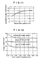
- the skin layer in this test was the same as that of the second embodiment. Specifically, it was formed by applying and sintering as a coating solution what was obtained by mixing 80wt% of glass frit (SiO 2 : 10%, ZnO : 65% and B 2 O 3 : 25%) and 20wt% of titanium dioxide. In other aspects it was the same as that of Test 1. The measurement results are shown in Figure 9.
- the flame length change pattern was similar to that in Test 1.
- the initial flame length was 20mm
- the flame length after 10 seconds and the saturated flame length were about 40mm
- the flame thickness was 7mm. A thin and long flame shape was thus obtained.
- the composition of the skin layer in this test was the same as that in Test 1 (first embodiment).
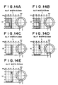
- the time-course change in flame length during burning was measured when the projection length of the flame-producing section from the wick holder was varied between 1mm and 4mm. The results are shown in Figure 10.
- the relationship between the saturated flame length and the projection length is shown in Figure 11.
- the saturated flame length grew longer with increasing length of the projection length of the flame-producing section. This was because volatized fuel gas from the side surfaces corresponding to the projection length of the flame-producing section was added to the volatized fuel gas from the tip end surface of the wick. However, owing to the cross-sectional area and the liquid fuel draw-up capacity of the wick with increasing length of the projection length, the saturated flame length was not proportional to the projection length but reached a limit (see Figure 11).
- the projection length thereof is set, in accordance with its thickness and draw-up capacity, so that the saturated flame length considered to be required by the fire-lighting device is obtained up to the vicinity where the saturated flame length reaches its limit.
- this also enables the projection length of the flame-producing section from the wick holder to be shortened and is advantageous from the aspect of design.
- the projection length of the wick can be shortened to facilitate structural design.
- the wick having the skin layer of this invention suppressed fuel volatization from the side surfaces of the flame-producing section, thereby thinning the flame thickness, so that its fuel consumption was greatly reduced compared with that of the comparative example.
- the burning period was set at 2.5 seconds in this test because the flame length immediately after lighting differs between a wick provided with the skin layer and one not provided therewith, as pointed out earlier, but becomes the same, at 28mm, at 2.5 seconds after lighting (see Figure 8).
- the burning period was therefore set to this time period.
- This time period is also appropriate from the practical aspect because, in the case of a cigarette lighter, the burning time for lighting a cigarette is ordinarily within 2.5 seconds.
- the skin layer in this test had the same composition as that in Test 1 and features other than the skin layer were similarly formed.
- Burning test was conducted at skin layer thickness varied from 0.1mm to 0.7mm by varying the amount of the coating solution applied.
- the relationship between skin layer thickness and initial flame length, flame length after 2 seconds and saturated flame length is shown in Figure 12.
- the relationship between skin layer thickness and flame thickness is shown in Figure 13.
- the skin layer thickness affects the volatization suppressing action, the various flame lengths became shorter and the flame thickness became thinner with increasing skin layer thickness, and that this action saturated and became substantially constant when the thickness exceeded 0.3mm. From this it follows that the skin layer should preferably be formed to a thickness of 0.2-0.5mm.
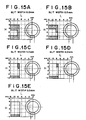
- the distance L from the center of contact between the flint and the rotating striker wheel to the center line of the wick was varied between 7mm and 12mm in increments of 1mm.
- the diameter of the rotating striker wheel was 6mm
- the diameter of the side wheels was 8mm
- the diameter of the flint was 2mm.
- the height H was defined with respect to the location of the upper end of the wick, locations of the contact point between the rotating striker wheel and the flint moved upward and downward being defined as positive and negative, respectively.
- the height H at distance L was varied between - 2mm and 6mm in increments of 1mm.
- Figures 14A-14E are cases where a slit was formed in the skin layer of a compressed surface of the wick and disposed to face the igniter.
- Figures 15A-15E are cases where a slit was formed in the skin layer of a cut surface perpendicular to the compressed surfaces and disposed to face the igniter.
- the lighting test was conducted with the wick and the igniter in the positional relationships of the test range bound by solid lines.
- the good lighting range, in which ignition occurred after one or two lighting operations, is indicated as blank and the poor lighting range, in which three or more lighting operations were needed before lighting, is indicated as hatched.
- Figures 14A-14E and Figures 15A-15E show that good igniting performance is obtained over a wide range when a slit of a slit width of about 1mm or greater is formed. They also show that the range within which lighting is possible is greater when a cut surface of the wick is directed toward the igniter than when a compressed surface is so directed.
Landscapes
- Engineering & Computer Science (AREA)
- Chemical & Material Sciences (AREA)
- Combustion & Propulsion (AREA)
- General Engineering & Computer Science (AREA)
- Mechanical Engineering (AREA)
- Lighters Containing Fuel (AREA)
Claims (21)
- Dans un brûleur (1) à carburant liquide dans lequel le carburant liquide est imprégné dans une matière de bourrage (3) logée dans un réservoir de carburant (2) et qui est équipé d'une mèche (6, 60) présentant une partie étirée (62) en contact avec la matière de bourrage (3) pour aspirer par capillarité du carburant liquide et le brûler à une partie de pointe (61) produisant la flamme et d'un allumeur (10) pour allumer la partie (61) produisant la flamme, une mèche (6, 60) pour brûleur à carburant liquide et qui est constituée d'un matériau poreux et d'au moins une surface latérale (6b) ne comprenant pas la surface d'extrémité supérieure (60) de la partie (61) produisant la flamme, est munie d'une couche de peau (8) pour supprimer la vaporisation du carburant liquide, et est caractérisée en ce que, dans la mèche (6, 60), l'action de suppression de la vaporisation du carburant liquide sur une surface latérale (6b) du côté de l'allumeur (10) est plus faible que l'action de suppression de la vaporisation sur les autres surfaces latérales.
- Une mèche (6, 60) selon la revendication 1, caractérisée en ce que la surface latérale de la mèche (6, 60) du côté de l'allumeur (10) est partiellement formée avec la couche de peau (8).
- Une mèche (6, 60) selon la revendication 1, caractérisée en ce que la surface latérale de la mèche (6, 60) du côté de l'allumeur (10) n'est pas formée avec la couche de peau (8).
- Une mèche (6, 60) selon la revendication 1, caractérisée en ce que la couche de peau (8) est un revêtement poreux présentant une perméabilité au carburant liquide plus faible que la perméabilité à l'intérieur de la mèche.
- Une mèche (6, 60) selon la revendication 1, caractérisée en ce que la couche de peau (8) est constituée par l'application de ou l'immersion dans ce qui est obtenu en mélangeant une poudre d'oxyde métallique et un liant, et en réalisant la solidification par séchage.
- Une mèche (6, 60) selon la revendication 5, caractérisée en ce que la poudre d'oxyde métallique comprend au moins l'un parmi l'oxyde de titane et l'oxyde d'aluminium.
- Une mèche (6, 60) selon la revendication 1, caractérisée en ce que la couche de peau (8) est constituée par l'application de ou l'immersion dans ce qui est obtenu en mélangeant une poudre composite minérale et résistante à la chaleur, une poudre métallique ou leur mélange et un liant, et en réalisant la solidification par séchage.
- Une mèche (6, 60) selon la revendication 5 ou 7, caractérisée en ce que le liant est un matériau de verre soluble composé de silicate de sodium, de silicate de potassium ou similaire.
- Une mèche (6, 60) selon la revendication 5 ou 7, caractérisée en ce que le liant est un matériau de verre soluble à bas point de fusion.
- Une mèche (6, 60) selon la revendication 1, caractérisée en ce que la couche de peau (8) est constituée par application de, ou immersion dans une peinture résistante à la chaleur, et séchage.
- Une mèche (6, 60) selon la revendication 1, caractérisée en ce que la couche de peau (8) contient un composé métallique présentant une réaction colorant la flamme.
- Une mèche (6, 60) selon la revendication 1, caractérisée en ce que la couche de peau (8) reçoit une addition de carbone.
- Une mèche (6, 60) selon la revendication 1, caractérisée en ce qu'après sa formation, la couche de peau (8) reçoit une application d'une solution de revêtement contenant du carbone.
- Une mèche (6, 60) selon la revendication 1, caractérisée en ce que la perméabilité au carburant liquide de la couche de peau (8) diffère entre l'extrémité supérieure et d'autres portions de la partie (61) produisant la flamme.
- Une mèche (6, 60) selon la revendication 14, caractérisée en ce que la couche de peau (8) présente une différence d'épaisseur entre l'extrémité supérieure et d'autres portions de la partie (61 ) produisant la flamme.
- Une mèche (6, 60) selon la revendication 1, caractérisée en ce que la couche de peau (8) présente une épaisseur de 0,2 mm à 0,5 mm.
- Une mèche (6, 60) selon la revendication 1, caractérisée en ce que la mèche (6, 60) est formée d'un matériau résistant à la chaleur tel que de la fibre céramiques ou des fibres de verre pour présenter une forme de barre à section transversale rectangulaire.
- Une mèche (6, 60) selon la revendication 1, caractérisée en ce que la mèche (6, 60) est composée d'un matériau de céramique poreuse ou de verre poreux.
- Une mèche (6, 60) selon la revendication 1, caractérisée en ce que la surface d'extrémité de pointe de la mèche (6, 60) munie de la couche de peau (8) est formée comme une surface inclinée qui est disposée en face de l'allumeur (10).
- Une mèche (6, 60) selon la revendication 1 ou 17, caractérisée en ce que la mèche (6, 60) est constituée d'un matériau poreux formé par compression dans une direction perpendiculaire à la direction axiale de la mèche (6, 60) et en ce qu'une surface comprimée pendant le formage par compression est disposée en face de l'allumeur (10) lorsque la formation de la couche de peau (8) fait en sorte que la quantité globale de vaporisation en provenance des surfaces latérales soit importante.
- Une mèche (6, 60) selon la revendication 1 ou 17, caractérisée en ce que la mèche (6, 60) est constituée d'un matériau poreux formé par compression dans une direction perpendiculaire à la direction axiale de la mèche (6, 60) et en ce qu'une surface perpendiculaire à une surface comprimée pendant le formage par compression est disposée en face de l'allumeur (10) lorsque la formation de la couche de peau (8) fait en sorte que la quantité globale de vaporisation en provenance des surfaces latérales soit réduite.
Applications Claiming Priority (5)
| Application Number | Priority Date | Filing Date | Title |
|---|---|---|---|
| JP1262098 | 1998-01-26 | ||
| JP1262098 | 1998-01-26 | ||
| JP07024798A JP3628512B2 (ja) | 1998-01-26 | 1998-03-19 | 液体燃料燃焼器具の燃焼芯 |
| JP7024798 | 1998-03-19 | ||
| PCT/JP1999/000298 WO1999037953A1 (fr) | 1998-01-26 | 1999-01-26 | Meche de combustion d'une chambre de combustion de combustible liquide |
Publications (3)
| Publication Number | Publication Date |
|---|---|
| EP0978686A1 EP0978686A1 (fr) | 2000-02-09 |
| EP0978686A4 EP0978686A4 (fr) | 2001-04-11 |
| EP0978686B1 true EP0978686B1 (fr) | 2004-04-07 |
Family
ID=26348246
Family Applications (1)
| Application Number | Title | Priority Date | Filing Date |
|---|---|---|---|
| EP99900677A Expired - Lifetime EP0978686B1 (fr) | 1998-01-26 | 1999-01-26 | Meche de combustion d'une chambre de combustion de combustible liquide |
Country Status (8)
| Country | Link |
|---|---|
| EP (1) | EP0978686B1 (fr) |
| JP (1) | JP3628512B2 (fr) |
| KR (1) | KR20010005639A (fr) |
| CN (1) | CN1125264C (fr) |
| DE (1) | DE69916187T2 (fr) |
| ES (1) | ES2215373T3 (fr) |
| ID (1) | ID22694A (fr) |
| WO (1) | WO1999037953A1 (fr) |
Cited By (2)
| Publication number | Priority date | Publication date | Assignee | Title |
|---|---|---|---|---|
| DE102005023970A1 (de) * | 2005-05-20 | 2006-11-23 | Peter Metzner | Kerze mit Korona-Effekt für längere Brenndauer |
| US9353942B2 (en) | 2005-09-13 | 2016-05-31 | Clean Fire System B.V. | Burner for household or recreational use |
Families Citing this family (11)
| Publication number | Priority date | Publication date | Assignee | Title |
|---|---|---|---|---|
| US20040041285A1 (en) * | 2002-06-20 | 2004-03-04 | Jian Xiang | Multi-component flow regulator wicks and methods of making multi-component flow regulator wicks |
| DE20210493U1 (de) * | 2002-07-06 | 2003-11-27 | Georg-August-Universität Göttingen | Katheterfixierung |
| JP4699740B2 (ja) * | 2004-11-02 | 2011-06-15 | 東京パイプ株式会社 | ライタ |
| DE102006056301B4 (de) * | 2006-11-29 | 2008-11-20 | Kühle, Raphael | Docht und sein Herstellungsverfahren sowie Dochthalter |
| WO2009071100A1 (fr) * | 2007-12-06 | 2009-06-11 | Ideas Denmark A/S | Mèche pour brûleur à combustible |
| DE102014103812A1 (de) * | 2014-03-20 | 2015-09-24 | Webasto SE | Verdampferbrenner für ein mobiles, mit flüssigem Brennstoff betriebenes Heizgerät |
| DE102015117137B4 (de) | 2015-10-07 | 2019-01-31 | Günter Grygier | Unverbrennbarer Docht für ein mit brennbarer Masse betriebenes Licht, Verfahren zu seiner Herstellung und Behälter mit brennbarer Masse und Docht |
| CN105570886A (zh) * | 2016-03-10 | 2016-05-11 | 桂林市淦隆环保科技有限公司 | 毛细陶瓷自吸式灯芯及火炉 |
| JP6225219B1 (ja) * | 2016-06-01 | 2017-11-01 | 岩谷産業株式会社 | 水素炎着色装置 |
| JP2019095143A (ja) * | 2017-11-24 | 2019-06-20 | 株式会社ニイタカ | 燃焼容器及び液体燃料 |
| DE102019000553A1 (de) * | 2019-01-25 | 2020-07-30 | Thomas Moog | Beleuchtungseinheit mit Flamme |
Family Cites Families (9)
| Publication number | Priority date | Publication date | Assignee | Title |
|---|---|---|---|---|
| JPS5836248B2 (ja) * | 1978-10-17 | 1983-08-08 | 松下電器産業株式会社 | 燃焼機器用バ−ナ− |
| JPS5575106A (en) * | 1978-11-30 | 1980-06-06 | Matsushita Electric Ind Co Ltd | Liquid fuel combustion device |
| JPS5710610U (fr) * | 1980-06-11 | 1982-01-20 | ||
| JPS5762309A (en) * | 1980-10-01 | 1982-04-15 | Matsushita Electric Ind Co Ltd | Combustion wick |
| JPS57115606A (en) * | 1981-01-07 | 1982-07-19 | Matsushita Electric Ind Co Ltd | Combustion wick |
| JPS6138315A (ja) * | 1984-07-31 | 1986-02-24 | Matsushita Electric Ind Co Ltd | 燃焼芯 |
| JPH03247915A (ja) * | 1990-02-23 | 1991-11-06 | Gakken Co Ltd | 着色炎を発する燃焼具及びその燃焼芯の製造法 |
| JPH0473703U (fr) * | 1990-10-30 | 1992-06-29 | ||
| DE4327437A1 (de) * | 1993-08-14 | 1995-02-16 | Helmut Jung | Kapillarer Dochteinsatz |
-
1998
- 1998-03-19 JP JP07024798A patent/JP3628512B2/ja not_active Expired - Fee Related
-
1999
- 1999-01-26 ES ES99900677T patent/ES2215373T3/es not_active Expired - Lifetime
- 1999-01-26 CN CN99800300A patent/CN1125264C/zh not_active Expired - Fee Related
- 1999-01-26 WO PCT/JP1999/000298 patent/WO1999037953A1/fr not_active Application Discontinuation
- 1999-01-26 KR KR1019997008706A patent/KR20010005639A/ko not_active Application Discontinuation
- 1999-01-26 DE DE69916187T patent/DE69916187T2/de not_active Expired - Fee Related
- 1999-01-26 EP EP99900677A patent/EP0978686B1/fr not_active Expired - Lifetime
- 1999-01-26 ID IDW991111A patent/ID22694A/id unknown
Cited By (2)
| Publication number | Priority date | Publication date | Assignee | Title |
|---|---|---|---|---|
| DE102005023970A1 (de) * | 2005-05-20 | 2006-11-23 | Peter Metzner | Kerze mit Korona-Effekt für längere Brenndauer |
| US9353942B2 (en) | 2005-09-13 | 2016-05-31 | Clean Fire System B.V. | Burner for household or recreational use |
Also Published As
| Publication number | Publication date |
|---|---|
| JPH11270847A (ja) | 1999-10-05 |
| CN1125264C (zh) | 2003-10-22 |
| WO1999037953A1 (fr) | 1999-07-29 |
| ES2215373T3 (es) | 2004-10-01 |
| DE69916187D1 (de) | 2004-05-13 |
| DE69916187T2 (de) | 2004-08-26 |
| CN1258343A (zh) | 2000-06-28 |
| ID22694A (id) | 1999-12-09 |
| EP0978686A4 (fr) | 2001-04-11 |
| JP3628512B2 (ja) | 2005-03-16 |
| EP0978686A1 (fr) | 2000-02-09 |
| KR20010005639A (ko) | 2001-01-15 |
Similar Documents
| Publication | Publication Date | Title |
|---|---|---|
| EP0978686B1 (fr) | Meche de combustion d'une chambre de combustion de combustible liquide | |
| RU2157953C1 (ru) | Горелка на жидком топливе | |
| EP0926443B1 (fr) | Meche de combustion pour appareil brulant un combustible liquide | |
| JP3285502B2 (ja) | 液体燃料用燃焼器具 | |
| US6227844B1 (en) | Combustor structure for igniters | |
| US6113385A (en) | Combustion wick for liquid fuel combustion appliances | |
| US6102688A (en) | Combustion apparatus for liquid fuel and combustion wick | |
| JP3545551B2 (ja) | 液体燃料用燃焼器具 | |
| WO1998011176A1 (fr) | Combustible liquide pour dispositifs a combustion, et dispositif a combustion | |
| WO1999034147A1 (fr) | Briquet a carburant liquide | |
| WO1999067573A1 (fr) | Dispositif de combustion de combustible liquide | |
| JPH11270848A (ja) | アルコールライター | |
| JPH10232020A (ja) | 液体燃料用燃焼器具における燃焼芯 | |
| JPH11223339A (ja) | 液体燃料燃焼器具の燃料保持部材 | |
| MXPA98005117A (en) | Combustion wick for liquid fuel combustion appliance | |
| MXPA98008702A (es) | Aparato de combustion para combustible liquido y mecha de combustion |
Legal Events
| Date | Code | Title | Description |
|---|---|---|---|
| PUAI | Public reference made under article 153(3) epc to a published international application that has entered the european phase |
Free format text: ORIGINAL CODE: 0009012 |
|
| 17P | Request for examination filed |
Effective date: 19990927 |
|
| AK | Designated contracting states |
Kind code of ref document: A1 Designated state(s): DE DK ES FR GB IT NL SE |
|
| A4 | Supplementary search report drawn up and despatched |
Effective date: 20010223 |
|
| AK | Designated contracting states |
Kind code of ref document: A4 Designated state(s): DE DK ES FR GB IT NL SE |
|
| 17Q | First examination report despatched |
Effective date: 20030227 |
|
| GRAP | Despatch of communication of intention to grant a patent |
Free format text: ORIGINAL CODE: EPIDOSNIGR1 |
|
| GRAS | Grant fee paid |
Free format text: ORIGINAL CODE: EPIDOSNIGR3 |
|
| GRAA | (expected) grant |
Free format text: ORIGINAL CODE: 0009210 |
|
| AK | Designated contracting states |
Kind code of ref document: B1 Designated state(s): DE DK ES FR GB IT NL SE |
|
| PG25 | Lapsed in a contracting state [announced via postgrant information from national office to epo] |
Ref country code: IT Free format text: LAPSE BECAUSE OF FAILURE TO SUBMIT A TRANSLATION OF THE DESCRIPTION OR TO PAY THE FEE WITHIN THE PRE;WARNING: LAPSES OF ITALIAN PATENTS WITH EFFECTIVE DATE BEFORE 2007 MAY HAVE OCCURRED AT ANY TIME BEFORE 2007. THE CORRECT EFFECTIVE DATE MAY BE DIFFERENT FROM THE ONE RECORDED.SCRIBED TIME-LIMIT Effective date: 20040407 |
|
| REG | Reference to a national code |
Ref country code: GB Ref legal event code: FG4D |
|
| REF | Corresponds to: |
Ref document number: 69916187 Country of ref document: DE Date of ref document: 20040513 Kind code of ref document: P |
|
| PG25 | Lapsed in a contracting state [announced via postgrant information from national office to epo] |
Ref country code: SE Free format text: LAPSE BECAUSE OF FAILURE TO SUBMIT A TRANSLATION OF THE DESCRIPTION OR TO PAY THE FEE WITHIN THE PRESCRIBED TIME-LIMIT Effective date: 20040707 Ref country code: DK Free format text: LAPSE BECAUSE OF FAILURE TO SUBMIT A TRANSLATION OF THE DESCRIPTION OR TO PAY THE FEE WITHIN THE PRESCRIBED TIME-LIMIT Effective date: 20040707 |
|
| REG | Reference to a national code |
Ref country code: ES Ref legal event code: FG2A Ref document number: 2215373 Country of ref document: ES Kind code of ref document: T3 |
|
| ET | Fr: translation filed | ||
| PG25 | Lapsed in a contracting state [announced via postgrant information from national office to epo] |
Ref country code: GB Free format text: LAPSE BECAUSE OF NON-PAYMENT OF DUE FEES Effective date: 20050126 |
|
| PG25 | Lapsed in a contracting state [announced via postgrant information from national office to epo] |
Ref country code: ES Free format text: LAPSE BECAUSE OF NON-PAYMENT OF DUE FEES Effective date: 20050127 |
|
| PLBE | No opposition filed within time limit |
Free format text: ORIGINAL CODE: 0009261 |
|
| STAA | Information on the status of an ep patent application or granted ep patent |
Free format text: STATUS: NO OPPOSITION FILED WITHIN TIME LIMIT |
|
| 26N | No opposition filed |
Effective date: 20050110 |
|
| PG25 | Lapsed in a contracting state [announced via postgrant information from national office to epo] |
Ref country code: NL Free format text: LAPSE BECAUSE OF NON-PAYMENT OF DUE FEES Effective date: 20050801 |
|
| PG25 | Lapsed in a contracting state [announced via postgrant information from national office to epo] |
Ref country code: DE Free format text: LAPSE BECAUSE OF NON-PAYMENT OF DUE FEES Effective date: 20050802 |
|
| GBPC | Gb: european patent ceased through non-payment of renewal fee |
Effective date: 20050126 |
|
| PG25 | Lapsed in a contracting state [announced via postgrant information from national office to epo] |
Ref country code: FR Free format text: LAPSE BECAUSE OF NON-PAYMENT OF DUE FEES Effective date: 20050930 |
|
| NLV4 | Nl: lapsed or anulled due to non-payment of the annual fee |
Effective date: 20050801 |
|
| REG | Reference to a national code |
Ref country code: FR Ref legal event code: ST |
|
| REG | Reference to a national code |
Ref country code: ES Ref legal event code: FD2A Effective date: 20050127 |