EP0978637A2 - Ventilsteuerungseinrichtung für einem Brennkraftmaschine - Google Patents
Ventilsteuerungseinrichtung für einem Brennkraftmaschine Download PDFInfo
- Publication number
- EP0978637A2 EP0978637A2 EP99115261A EP99115261A EP0978637A2 EP 0978637 A2 EP0978637 A2 EP 0978637A2 EP 99115261 A EP99115261 A EP 99115261A EP 99115261 A EP99115261 A EP 99115261A EP 0978637 A2 EP0978637 A2 EP 0978637A2
- Authority
- EP
- European Patent Office
- Prior art keywords
- roller shaft
- groove
- support wall
- valve operating
- cam
- Prior art date
- Legal status (The legal status is an assumption and is not a legal conclusion. Google has not performed a legal analysis and makes no representation as to the accuracy of the status listed.)
- Granted
Links
Images


Classifications
-
- F—MECHANICAL ENGINEERING; LIGHTING; HEATING; WEAPONS; BLASTING
- F01—MACHINES OR ENGINES IN GENERAL; ENGINE PLANTS IN GENERAL; STEAM ENGINES
- F01L—CYCLICALLY OPERATING VALVES FOR MACHINES OR ENGINES
- F01L13/00—Modifications of valve-gear to facilitate reversing, braking, starting, changing compression ratio, or other specific operations
- F01L13/0015—Modifications of valve-gear to facilitate reversing, braking, starting, changing compression ratio, or other specific operations for optimising engine performances by modifying valve lift according to various working parameters, e.g. rotational speed, load, torque
- F01L13/0036—Modifications of valve-gear to facilitate reversing, braking, starting, changing compression ratio, or other specific operations for optimising engine performances by modifying valve lift according to various working parameters, e.g. rotational speed, load, torque the valves being driven by two or more cams with different shape, size or timing or a single cam profiled in axial and radial direction
-
- F—MECHANICAL ENGINEERING; LIGHTING; HEATING; WEAPONS; BLASTING
- F01—MACHINES OR ENGINES IN GENERAL; ENGINE PLANTS IN GENERAL; STEAM ENGINES
- F01L—CYCLICALLY OPERATING VALVES FOR MACHINES OR ENGINES
- F01L1/00—Valve-gear or valve arrangements, e.g. lift-valve gear
- F01L1/26—Valve-gear or valve arrangements, e.g. lift-valve gear characterised by the provision of two or more valves operated simultaneously by same transmitting-gear; peculiar to machines or engines with more than two lift-valves per cylinder
- F01L1/267—Valve-gear or valve arrangements, e.g. lift-valve gear characterised by the provision of two or more valves operated simultaneously by same transmitting-gear; peculiar to machines or engines with more than two lift-valves per cylinder with means for varying the timing or the lift of the valves
-
- F—MECHANICAL ENGINEERING; LIGHTING; HEATING; WEAPONS; BLASTING
- F01—MACHINES OR ENGINES IN GENERAL; ENGINE PLANTS IN GENERAL; STEAM ENGINES
- F01L—CYCLICALLY OPERATING VALVES FOR MACHINES OR ENGINES
- F01L2305/00—Valve arrangements comprising rollers
Definitions
- the present invention relates to a valve operating system for an internal combustion engine, which uses a rollered cam follower including a pair of support walls which are integrally formed on a cam follower body and arranged in parallel to sandwich a roller therebetween, so that outer peripheries of opposite ends of a roller shaft having the roller rotatably carried thereon are supported in through-bores in the support walls, and particularly, to a valve operating system suitable for an internal combustion engine, which includes a plurality of rollered cam followers disposed adjacent one another and having rollers put into contact with a plurality of cams, respectively, at least a portion of the cam followers being operatively connected to an engine valve, so that the valve operating characteristic of the engine valve can be changed by the movement of a switching pin which is mounted to be slidingly movable astride adjacent cam followers, thereby enabling the connected and disconnected states of the cam followers to be switched over from one to another.
- the above-described rollered cam follower is designed so that the slidability and the followability with respect to a cam of the cam follower are enhanced by the roller placed in contact with the cam.
- Such rollered cam follower is conventionally widely used in valve operating systems for internal combustion engines.
- a valve operating system for an internal combustion engine comprising at least two rollered cam followers arranged adjacent each other and having rollers put in contact with a plurality of cams, at least one of the cam followers being operatively connected to an engine valve, so that the valve operating characteristic of the engine valve can be changed by moving a switching pin mounted in adjacent ones of the cam followers for sliding movement astride the adjacent cam followers, thereby enabling connected and disconnected states of the cam followers to be switched over from one to another, wherein each of the cam followers comprises a cam follower body having a pair of support walls integrally provided thereon and arranged in parallel to sandwich the roller therebetween, and a hollow roller shaft which is fitted and supported at outer peripheries of opposite ends thereof in through-bores in the support walls, the roller shaft having the roller rotatably carried at an intermediate portion thereof; and the system further includes a first groove defined in an inner peripheral surface of the through-bore in one of the support walls to extend in
- the axial relative sliding movement of the roller shaft relative to the through-bores in the support walls in the roller shaft can be reliably inhibited by the C-shaped resilient fastener disposed between the fitted faces of one end of the roller shaft of the rollered cam follower and through bore in one of the support walls of the cam follower body (i.e., between the first and second grooves). Therefore, the roller shaft can be fixed in a slip-off preventing manner to the support wall without special use of a caulking equipment. Moreover, a protrusion for fixing the roller shaft is not present on the outer surface of the support wall and hence, the width of the cam follower can be decreased correspondingly.
- the roller shaft is hollow, and the switching pin for switching-over the connected and disconnected states of the adjacent cam followers is slidably fitted to the inner peripheral surface of the roller shaft. Therefore, the roller shaft can also be used as a portion of a cam follower connecting mechanism, leading to a correspondingly simplified structure.
- the roller shaft In fixing the roller shaft, there is not a possibility that any deformation or strain is produced in the roller shaft as when the roller shaft is fixed by caulking. Therefore, not only the outer peripheral surface (the roller rolling face) and the inner peripheral surface (the switching pin sliding face) of the roller shaft can be formed into smooth surfaces to the utmost. Therefore, the rotation of the roller on the outer peripheral surface of the roller shaft is smooth, but also the switching pin can be slid smoothly on the inner peripheral surface of the roller shaft, whereby the valve operating characteristic can be switched over precisely.
- the cam followers include a particular cam follower which is not operatively connected to the engine valve in the disconnected state of the cam followers.
- the particular cam follower may be provided with a portion receiving the biasing force of a biasing means for normally biasing the particular cam follower toward the corresponding cam.
- the receiving portion may be formed on the other support wall of the particular cam follower.
- the receiving portion of the biasing means is located on that side of the particular cam follower on which the resilient fastener is not present, i.e., on the support wall in which the first groove is not present (on the other support wall), and there is not a possibility that the rigidity of the receiving portion is reduced due to the presence of the first groove. Therefore, a sufficient rigidity can be ensured in the receiving portion without a special reinforcement.
- the closing wall is positioned outside one of the pair of support walls of the cam follower, on which the resilient fastener is not present (i.e., the other wall). Therefore, even if the roller shaft is inserted into the support wall from the opposite side from the closing wall to keep out of the closing wall, the resilient fastener can be positioned on the side of insertion opening and hence, the assembling operation can be easily performed without difficulty and without being influenced by the presence of the closing wall.
- the roller is carried on the outer periphery of the roller shaft through needles, and that area of the outer peripheral surface of the roller shaft, which extends from its central needle-rolling face to an outer area past inner end edges of the through-bores, has been subjected at least to a hardening treatment, the wear of the needle rolling face can be reduced, and the roller can be rotated smoothly on the rolling face over a log period of time.
- portion of the outer periphery of the roller shaft receiving a larger struck load (a shearing load) applied thereto from the cam which corresponds to a boundary between each of the support walls and the roller (i.e., a portion in the vicinity of each of the inner end edges of the through-bores) can be effectively reinforced to effectively avoid the deformation and the fracture of the roller shaft due to the shearing load.
- the insertion and removal of the switching pin for changing the valve operating characteristic is performed at those ends of the roller shaft and the cam follower, in which the first and second grooves are not present therein (therefore, the rigidity is not reduced).
- the insertion and removal of the switching pin can be performed always smoothly. Even in a state in which the switching pin is located astride the two roller shaft, i.e., in a state in which the adjacent cam followers have been connected to each other, the connecting load can be received by a portion having a relatively high rigidity, which is convenient for increasing the connection strength.
- each of the first and second grooves is formed into a C-shape, so that the relative rotation of the roller shaft and the support wall is limited by the C-shaped resilient fastener. That area of the inner peripheral portion of the through-bore in the one support wall, which is sandwiched between opposite ends of the first groove, may be disposed to correspond to a free end of the one support wall.
- the free end of the support wall of the cam follower need not be formed to be specially thicker, despite the provision of the first groove. Therefore, the inertial mass of the free end of the support wall is reduced, and the followability of the cam follower to the cam is enhanced.
- each of the first and second grooves is formed into a C-shape, so that the relative rotation of the roller shaft and the support wall is limited by the C-shaped resilient fastener.
- the cam followers include a particular cam follower which is not operatively connected to the engine valve in the disconnected state of the cam followers, the particular cam follower may be provided with a portion receiving the biasing force of the biasing means for normally biasing the particular cam follower toward the corresponding cam.
- the receiving portion may be disposed such that an area of the inner peripheral surface of the through-bore in the one support wall in the particular cam follower, which is sandwiched between the opposite ends of the first groove, corresponds to the receiving portion provided on the one support wall.
- each of the first and second grooves is formed into a C-shape, so that the relative rotation of the roller shaft and the support wall is limited by the C-shaped resilient fastener.
- the cam followers include a particular cam follower which is not operatively connected to the engine valve in the disconnected state of the cam followers, the particular cam follower being engaged by biasing means for normally biasing the particular cam follower toward a corresponding cam that portion of the one support wall in the particular cam follower which is opposed to the biasing means may be formed thicker in a radial direction of the roller shaft, so that an outer surface of the portion protrudes toward the biasing means.
- the thicker portion is a portion receiving the biasing force of the biasing means, and the first groove may be located between two planes extending through opposite sides of the receiving portion and perpendicular to the axis of the roller shaft.
- the biasing force of the biasing means can be received stably by the thicker receiving portion.
- the first groove is defined in the inner peripheral surface of the through-bore in the one support wall, a reduction in rigidity due to the formation of the groove can be effectively compensated for by the thicker receiving portion.
- each of the first and second grooves is formed into a C-shape, so that the relative rotation of the roller shaft and the support wall is limited by the C-shaped resilient fastener.
- An area of the inner peripheral portion of the through-bore in the one support wall, which is sandwiched between opposite ends of the first groove, may be disposed to correspond to that portion of the cam follower body to which a compressing load is applied during a lifting operation.
- the compressing load-applied portion having a larger load burden during the lifting operation provided by the cam in the cam follower body need not be formed to be specially thicker, and hence, the size and weight of the cam follower body are reduced correspondingly.
- each of the first and second grooves may be formed into a C-shape, so that the relative rotation of the roller shaft and the support wall is limited by the C-shaped resilient fastener.
- the roller shaft can be reliably fixed both in an axial direction and in a rotational direction to the support wall by engagement of the fastener with the first and second grooves.
- opposite ends faces of the fastener may be formed flat and inclined with respect to a phantom plane extending radiately from the axis of the roller shaft toward the end of the fastener, and opposite inner end faces of the first and second C-shaped grooves opposed to the opposite end faces of the fastener may be formed into flat faces parallel to the corresponding opposite end faces of the fastener, respectively.
- the end faces of the fastener and the inner end faces of each of the grooves opposed to the end faces can be brought into face contact with each other with a sufficient wide contact area and hence, can be precisely brought into engagement with each other to reliably prevent the rotation of the roller shaft.
- the surface pressure of contact between the end faces of the fastener and the inner end faces of the hollow portion (each groove) can be reduced effectively to largely contribute to a reduction in wear of the contact portions.
- each of the inner end faces of the C-shaped first groove may be extended diametrically outwards past an outer peripheral edge portion of the fastener end face opposed to the inner end face of the first groove.
- a V-shaped recess (such a recess is liable to become a starting point for concentration of a stress) corresponding to the edge portion of the end face of the fastener is not present in the inner end face of the first groove in the support wall. Therefore, it is possible to effectively prevent the generation of fissures and cracks in the inner end face of the first groove due to the abutment of the inner end face against the edge portion and hence, the strength of supporting of the roller shaft by the support wall is increased.
- a phantom plane connecting the axis of the roller shaft and the rotational axis of the cam may be provided to pass through that area of the inner peripheral portion of the through-bore in the one support wall, which is sandwiched between the opposite ends of the first groove.
- the first groove can be defined to keep out of a stress-concentrated site produced due to a struck load applied from the cam substantially along the phantom plane to the roller shaft (the through-bore in the support wall). Therefore, reductions in rigidity and strength of such site is inhibited despite the provision of the first groove, which is particularly convenient when the cam follower body is formed of an aluminum-based metal material. In this case, if the phantom plane passes through a central portion of the above-described area, the reductions in rigidity and strength of the stress-concentrated site are inhibited further effectively.
- the cam follower body is formed of an aluminum-based metal material, the weight of the cam follower and in its turn, the inertial mass can be reduced.
- a first embodiment of the present invention with a rollered cam follower applied to a valve operating system for an internal combustion engine will be described with reference to Figs.1 to 4.
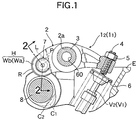
- two rollered rocker arms 1 1 and 1 2 as rollered cam followers are arranged adjacent each other at an upper portion of an engine body E and swingably carried on a common rocker shaft 3 fixed to the engine body E.
- Rollers R, R of the first and second rocker arms 1 1 and 1 2 are in contact with two cams (a low-speed cam C 1 and a high-speed cam C 2 in the illustrated embodiment) arranged on a cam shaft 8 rotatably carried on the engine body E and rotated in association with a crankshaft (not shown) of the internal combustion engine.
- the low-speed cam C 1 and the high-speed cam C 2 are formed to accommodate to a low-speed operation and a high-speed operation of the engine, respectively and moreover, formed so that the high-speed cam C 2 is higher in lift than the low-speed cam C 1 .
- a shaft bore 2a is defined in a lengthwise intermediate portion of a rocker arm body 2 of each of the rocker arms 1 1 and 1 2 , and a rocker shaft 3 is relatively rotatably mounted through the shaft bore 2a.
- An adjusting bolt 4 is screwed in a base portion of each of the rocker arm bodies 2, so that the screwed position thereof is fixed by a rock nut 5.
- Two intake valves V 1 and V 2 as engine valves per cylinder are vertically slidably carried on the engine body E with their upper ends abutting against lower ends of the adjusting bolts 4.
- the valves V 1 and V 2 are always biased in a closing direction by resilient force of a valve spring 6 (a direction to abut against the adjusting bolts 4).
- the roller R is rotatably mounted at a tip portion of each of the rocker arm bodies 2 through a roller shaft 7, and the cams C 1 and C 2 are brought into pressure contact with outer peripheral surfaces of the rollers R by the resilient force of the valve spring 6. If the low-speed and high-speed cams C 1 and C 2 are rotated in association with the crankshaft, the first and second rocker arms 1 1 and 1 2 abutting against the cams C 1 and C 2 through the rollers R can be vertically swung about the rocker shaft 3 to open and close the corresponding intake valves V 1 and V 2 .
- a fork-shaped roller retaining portion H are integrally formed at the tip portions of the rocker arm bodies 2 of the rocker arms 1 1 and 1 2 and has pairs of first and second support walls Wa and Wb arranged in parallel at a distance to sandwich the roller R therebetween.
- Through-bores 9a and 9b are coaxially defined across the support walls Wa and Wb, and outer peripheries of opposite ends of the roller shafts 7 are supported in the through-bores 9a and 9b in a fitted manner, respectively.
- the roller shaft 7 is formed into a hollow cylindrical shape with at least one end opened and with its diameter constant over the entire length.
- An outer peripheral surface of a lengthwise central portion 7m of the roller shaft 7 is a roller rolling surface, on which an inner periphery of the roller R is rotatably carried through a large number of needles N arranged in a circumferential direction thereof.
- the outer end faces of the roller shafts 7 are formed so that they do not protrude from outer surfaces of the support walls Wa and Wb (particularly, so that they are flush with the outer surfaces in the illustrated embodiment).
- the through-bores 9a and 9b in the support walls Wa and Wb are each formed into an arcuate shape with its inside diameter being constant over the entire width and moreover, being set to be substantially equal to the outside diameter of the roller shaft 7, so that they are fitted with the opposite ends 7a and 7b of the roller shafts 7 closely (i.e., for axial sliding movement, but with no looseness in a diametrical direction).
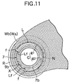
- a first groove g 1 having a C-shaped cross section is defined on the inner peripheral surface of the through-bore 9b in one of the support walls (the second support wall Wb in the illustrated embodiment) to extend in the circumferential direction of the through-bore 9b.
- a second groove g 2 having a C-shaped cross section is defined in the outer peripheral surface of that one end of the roller shaft 7 which corresponds to the one support wall Wb (the second end in the illustrated embodiment) to extend in the circumferential direction of the roller shaft 7 in correspondence to the first groove g 1 , and no groove is defined on the outer periphery of the other end of the shaft 7 (the first end in the illustrated embodiment).
- a C-shaped hollow portion G is defined between the first and second grooves g 1 and g 2 between fitted surfaces of the through-bore 9b in the second support wall Wb and the second end 7b of the roller shaft 7.
- a circlip L formed of a metal into the substantially same C-shape as the hollow portion G is mounted in the hollow portion G and constitutes a resilient fastener of the present invention.
- the circlip L in a state in which it has been set in the hollow portion G, can inhibit the relative rotation of the roller shaft 7 and the support walls Wa and Wb by one end face in contact with inner surfaces of one ends of the grooves g 1 and g 2 astride them and the other end in contact with inner surfaces of the other ends of the grooves g 1 and g 2 astride them, and also can inhibit the axial relative movement of the roller shaft 7 and the support walls Wa and Wb by one side in contact with the inner surfaces of one sides of the grooves g 1 and g 2 astride them and the other side in contact with the inner surfaces of the other sides of the grooves g 1 and g 2 astride them.
- the circlip L is formed so that its diameter is larger than the outside diameter of the roller shaft 7 (therefore, the inside diameter of the through-bores 9a and 9b) and also than inside diameter of the first groove g 1 in its free state. Therefore, The outer peripheral surface of the circlip L, in the state in which it has been set in the hollow portion G, is in pressure contact with the inner bottom surface of the first groove g 1 under the action of a resilient restoring force of the circlip L itself.
- the second groove g 2 in the roller shaft 7 has a depth which is set so that it can be forcibly deformed in a resiliently shrunk manner by a first jig (not shown), until the circlip L fitted in the second groove g 2 is immersed into the second groove g 2 .
- a somewhat play is established in the circumferential direction of the circlip L between opposite ends of the circlip L and opposite inner ends of the C-shaped hollow portion G, so that the diametrical resilient deformation during assembling of the circlip L can be permitted under no compulsion.
- roller shafts 7, 7 of the first and second rocker arms 1 1 and 1 2 is formed into a bottomed cylindrical shape with its second end 7b, 7b closed by a closing wall integral with or separate from the shaft 7 and with its first end 7a, 7a opened. Moreover, the roller shafts 7, 7 are arranged, so that their first ends 7a, 7a, with the second groove g 2 being not defined therein, adjoin each other.
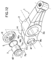
- a connection switch-over mechanism M is provided in the first and second rocker arms 1 1 and 1 2 and is capable of switching-over the state in which the first and second rocker arms 1 1 and 1 2 have been connected to each other and the state in which the first and second rocker arms 1 1 and 1 2 have been disconnected from each other.
- the connection switch-over mechanism M includes a switching pin P which is fitted to the inner peripheral surfaces of the roller shafts 7, 7 of the first and second rocker arms 1 1 and 1 2 for sliding movement astride the inner peripheral surfaces to enable the first and second rocker arms 1 1 and 1 2 to be switched over between the connected state and the disconnected state, a movement limiting member 21 slidably fitted to the inner peripheral surface of the roller shaft 7 of the second rocker arm 1 2 to define a retreating limit for the switching pin P, and a return spring 22 for biasing the switching pin P and the limiting member 21 in a disconnecting direction (leftwards as viewed in Fig.2).
- a closing wall 7bw for closing the opened end of the roller shaft 7 is secured in a post-mounted manner (i.e., after completion of assembling of the roller shaft 7) to the outside of the second support wall Wb of the first rocker arm 1 1 , and a working oil chamber 20 is defined between the closing wall 7bw and the switching pin P.
- the working oil chamber 20 is always in communication with an oil supply passage 60 within the rocker shaft 3 via oil passages 23 and 24 defined in the closing wall 7bw and the rocker arm body 2 of the first rocker arm 1 1 , respectively.
- the oil supply passage 60 can be selectively switchably put into communication with any of a hydraulic pressure source and an oil tank (both not shown) depending on the operational state of the engine.
- the switching pin P biased in a retreating direction by the hydraulic pressure of the working oil is in its connecting state (at a retreating limit) shown in Fig.2A to integrally connect the rocker arms 1 1 and 1 2 to each other.
- the switching pin P biased in an advancing direction by the resilient force of the return spring 22 is in a disconnecting state to disconnect the rocker arms 1 1 and 1 2 from each other.
- the inside of the working oil chamber 20 is put in its hydraulic pressure-released state to maintain the rocker arms 1 1 and 1 2 in their disconnected states shown in Fig.2B.
- the first rocker arm 1 1 is swung in response to the low-speed cam C 1 by the rotation of the cam shaft 8 to open and close the first intake valve V 1
- the second rocker arm 1 2 is swung in response to the high-speed cam C 2 to open and close the second intake valve V 2 .
- a valve operating mode corresponding to the low-speed operation is provided as a whole.
- the fixing of the hollow roller shaft 7 is performed using the C-shaped resilient circlip L, and hence, there is not a possibility that a deformation or a strain is produced in the roller shaft 7 as in the fixing performed by caulking, and the inner peripheral surface of the roller shaft 7 is formed smoothly. Therefore, the switching pin P can slide smoothly on the inner peripheral surface of the roller shaft 7 and hence, the switching-over of the valve operating characteristics is carried out precisely.
- a rocker arm body 2 for each of the rocker arms 1 1 and 1 2 is first fabricated. Then, a first groove g 1 is made by cutting in the through-bore 9b in the second support wall Wb at a roller-retaining portion H.
- a main portion for the first groove g 1 is first cut in the inner peripheral surface of the through-bore 9b by a groove-making cutter Cg fed in an arcuate shape along the inner periphery of the through-bore 9b, as shown in Fig.4A, and opposite end faces of the groove g 1 are then cut by another cutter (not shown) fed in the same direction to provide flat faces f extending in a substantially diametrical direction of the through-bore 9b, as shown in Fig.4B.
- the reason why the opposite end faces of the first groove g 1 are formed into the flat faces f is to ensure that they are properly engaged with flat opposite ends faces of the C-shaped circlip L to provide a satisfactory rotation-preventing effect.
- a roller shaft 7 is fabricated at a step different from the step of fabricating the rocker arm body 2. Then, a second groove g 2 is cut around the outer periphery of the second end 7b of the shaft 7, and the circlip L is fitted into the second groove g 2 .
- a roller R having a large number of needles N temporarily assembled to its inner periphery is inserted into and retained in a clearance between the first and second support walls Wa and Wb of the rocker arm body 2 by use of a second jig (not shown), so that the roller R is coaxial with the through-bores 9a and 9b in the support walls Wa and Wb.
- the roller 7 is inserted as left in the retained state with its first end 7a turned ahead sequentially into the through-bore 9b in the second support wall Wb and into the roller in such a manner that the phases of the first and second grooves g 1 and g 2 are matched with each other, and the second end 7b is fitted into the through-bore 9b in the second support wall Wb.
- the circlip L is forcibly retained in advance by the first jig (not shown) in a resiliently shrunk state in which it has been immersed into the second groove g 2 .
- the circlip L is released from the first jig at the time when it has reached the inside of the through-bore 9b with the fitting, and then slid within the through-bore 9b.
- the roller shaft 7 can be integrally fixed to the second support wall Wb (therefore, to the rocker arm body 2).
- the closing wall 7bw is secured by welding or the like to the outer surface of the second support wall Wb of the rocker arm 2, particularly, of the first rocker arm 1 1 .
- the roller shaft 7 can be fixed imply to the rocker arm body 2 without special caulking equipment, thereby achieving a corresponding reduction in cost.
- no protrusion for fixing the roller shaft exists on the outer surfaces of the support walls Wa and Wb, whereby the width of the rocker arm (the maximum dimension in a direction of the roller shaft) can be correspondingly decreased, leading to a reduction in size of the rocker arm 1.
- the roller shaft 7 is formed into a hollow shape for the purpose of providing a reduction in weight of the rocker arm 1.
- the roller shaft 7 is of such hollow structure, there is not a possibility that a deformation or a strain is produced in the roller shaft 7, as when the roller shaft 7 is fixed by caulking, and the inner peripheral surface of the roller shaft 7 and the outer peripheral surface of the central portion 7m of the roller shaft (the roller-rolling surface) can be formed into a smooth shape. Therefore, the switching pin P can be slid smoothly on the inner peripheral surface of the roller shaft 7.
- the switching-over of the valve operating characteristics can be performed precisely, and the roller R can be rotated always smoothly on the roller-rolling surface.
- the roller shaft 7 may receive a large struck load from the cam C, and a largest shearing force may act, due to the struck load, particularly on that portion of the roller shaft 7 which corresponds to a boundary between each of the support walls Wa and Wb and the roller R (i.e., a portion in the vicinity of each of the inner end edges 9a E and 9b E of the through-bores 9a and 9b in the support walls Wa and Wb).
- the second groove g 2 is disposed at a location axially spaced apart from the boundary-correspondence portion and hence, a reduction in strength (specifically, a deformation or a fracture) of the boundary-correspondence portion due to the provision of the groove g 2 is inhibited effectively.
- the switching pin P for changing the valve operating characteristics can be inserted into and removed from those ends of the rocker arm body 2 and the roller shaft 7 in which the first and second grooves g 1 and g 2 are not provided (therefore, the rigidity of which is not reduced). Therefore, the insertion and the removal of the switching pin P can be performed stably and smoothly. Even in a state in which the switching pin P has been located astride the two roller shafts 7, 7 (i.e., in a state in which the adjacent rocker arm bodies 2, 2 have been connected to each other), as shown in Fig.2A, the connecting load can be received by the higher-rigidity portion and hence, the strength is increased correspondingly.
- a closing wall 7bw is provided outside one, on which the resilient fastener L is not provided, (the first support wall Wa), of the pair of support walls Wa and Wb of the cam follower body 2 of, particularly the first rocker arm 1 1 to define a working oil chamber 20 between the closing wall 7bw and the switching pin P.
- the resilient fastener L can be positioned on the side of the inserting opening (i.e., on the side of the second support wall Wb), and the assembling operation can be easily performed without difficulty and without being influenced by the presence of the closing wall 7bw. For example, even if the closing wall 7bw is secured to the first support wall Wa in advance (i.e., before the insertion of the roller shaft 7), the operation of inserting the roller shaft 7 is not hindered.
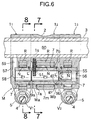
- FIG. 6 A third embodiment of the present invention will now be described with reference to Figs.6 to 9.
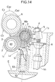
- three rollered rocker arms per cylinder are arranged adjacent one another and swingably carried on a common rocker shaft 3, as illustrated in the first embodiment, so that rollers R of the first, second and third rocker arms 1 1 , 1 2 and 1 3 are in contact with three cams (a low-speed cam C 1 , a high-speed cam C 2 and a stopping cam C 3 in the illustrated embodiment) integrally arranged side by side on a cam shaft 8.
- the low-speed cam C 1 and the high-speed cam C 2 are formed to correspond to the low-speed and high-speed operations of the engine, respectively and moreover, the high-speed cam C 2 is formed at a lift amount larger than that of the low-speed cam C 1 .
- the stopping cam C 3 is used for substantially stopping the corresponding intake valve V 2 and has a circular section basically corresponding to base circles of the low-speed and high-speed cams C 1 and C 2 , but has a smaller lobe Ca 3 slightly bulged from the base circle, which is provided at its portion corresponding to the lobes Ca 1 and Ca 2 of the low-speed and high-speed cams C 1 and C 2 .
- the first and third rocker arms 1 1 and 1 3 located on the opposite sides are operatively connected to first and second intake valves V 1 and V 2 as two engine valves of the same type provided per cylinder. Therefore, the intake valves V 1 and V 2 are opened and closed in response to the swinging movement of the first and third rocker arms 1 1 and 1 3 .
- the engine body E is provided with a lost motion mechanism Lo as a biasing means for normally biasing the second rocker arm 1 2 toward the corresponding high-speed cam C 2 .
- the lost motion mechanism Lo is comprised of a bottomed cylindrical guide member 51 swingably fitted and supported in a guide hole 50 which opens into an upper portion of the engine body E, and a spring 52 for resiliently biasing the guide member 51 toward the high-speed cam C 2 .
- a tip end of the guide member 51 is slidably in pressure contact with a receiving portion is integrally formed in a bulged manner on a lower surface of the first support wall Wa of the second rocker arm 1 2 .
- a connection switch-over mechanism M is provided in the first, second and third rocker arms 1 1 , 1 2 and 1 3 and is capable of switching-over the connected and disconnected state of these arms in accordance with the operational state of the engine.
- the connection switch-over mechanism M includes a first switching pin P 1 fitted in hollow portions of the roller shafts 7, 7 of the first and second rocker arms 1 1 and 1 2 for sliding movement astride the hollow portions to enable the first and second rocker arms 1 1 and 1 2 to be switched over between the connected and disconnected states, a second switching pin P 1 fitted in hollow portions of the roller shafts 7, 7 of the second and third rocker arms 1 2 and 1 3 for sliding movement astride the hollow portions to enable the second and third rocker arms 1 2 and 1 3 to be switched over between the connected and disconnected states, a movement limiting member 55 slidably fitted within the roller shaft 7 of the third rocker arm 1 3 to define retreating limits for the switching pins P 1 and P 2 , and a return spring 56 for biasing the switching pins P 1 and P 2
- a working oil chamber 58 is defined between the an outer roller-supporting wall 57 of the first rocker arm 1 1 and the switching pin P 1 and is normally in communication with an oil supply passage 60 within the rocker shaft 3 via an oil passage 59 within the first rocker arm 1 1 .
- the oil supply passage 60 is capable of being selectively put into communication with any of a hydraulic pressure source and an oil tank (both not shown) in accordance with the operational state of the engine.
- the inside of the working oil chamber 58 is put in a hydraulic pressure-released state, whereby the rocker arms 1 1 to 1 3 are maintained in their disconnected states shown in Fig. 6.
- the first rocker arm 1 1 is swung in response to the low-speed cam C 1 by the rotation of the cam shaft 8 to open and close the first intake valve V 1
- the third rocker arm 1 3 is swung extremely slightly (substantially stopped) in response to the stopping cam C 3 to bring the second intake valve V 2 into a substantially stopped state.
- a swirl fuel-air mixture is supplied efficiently only from one of the intake valve bores into the combustion chamber by opening and closing only the first intake valve V 1 in a valve operating mode for a low-speed operation corresponding the shape of the low-speed cam C 1 .
- the second rocker arm 1 2 which is not in association with the intake valves V 1 and V 2 is normally biased toward the high-speed cam C 2 by the lost motion mechanism Lo to normally follow the high-speed cam C 2 in contact with the latter without looseness.
- the fixing of the hollow roller shaft 7 is performed using the C-shaped resilient circlip L and hence, there is not a possibility that a deformation or a strain is produced in the roller shaft 7, as when the roller shaft is fixed by caulking. Therefore, the inner and outer peripheral surfaces of each of the roller shafts 7 are formed into a smooth shape, and a function and an effect similar to those in the first embodiment can be expected.
- the receiving portion 1s of the lost motion mechanism Lo as a biasing means is formed on that portion of the second rocker arm 1 2 in which the circlip L is not present, i.e., on the support wall free of the first groove g 1 (the first support wall Wa). Therefore, there is not a possibility that the rigidity of the receiving portion 1s is reduced due to the presence of the first groove g 1 and hence, the sufficient rigidity and strength of the receiving portion 1s can be ensured without special reinforcement of the receiving portion 1s.
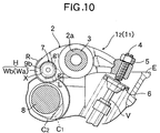
- a fourth embodiment of the present invention is shown in Figs.10 to 12.
- the fourth embodiment is basically the same in structure as the first embodiment, but is different from the first embodiment in respect of that an area X of the inner peripheral portion of the through-bore 9b in the second support wall Wb, which is sandwiched between the opposite ends of the first groove g 1 , is disposed to correspond to the free end (tip end) of the second support wall Wb, wherein an area in the first embodiment corresponding to the area X faces toward the rocker shaft 3.
- the other construction is similar to that in the first embodiment and hence, components or portions corresponding to those in the first embodiment are designated by the same reference characters as in the first embodiment.
- the free end of the second support wall Wb need not be formed specially at a larger thickness, despite the provision of the first groove g 1 . Therefore, a reduction in inertial mass of the free end is provided, and the followability of the rocker arm 1 to the cams C 1 and C 2 can be enhanced correspondingly.
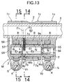
- a fifth embodiment of the present invention is shown in Figs.13 to 15.
- the fifth embodiment is basically the same in structure as the third embodiment, but is different from the first embodiment in respect of that a receiving portion 1s for the biasing means (the lost motion mechanism Lo) is provided on the second support wall Wb, particularly in the second rocker arm 1 2 , and an area X' of the inner peripheral portion of the through-bore 9b in the second support wall Wb, which is sandwiched between the opposite ends of the first groove g 1 , is disposed to correspond to the receiving portion 1s.
- the other construction is the same as in the first embodiment and hence, components or portions corresponding to those in th first embodiment are designated by the same reference characters as in the first embodiment.
- the reduction in rigidity of the receiving portion is in the support wall Wb can be avoided to the utmost, even if the first groove g 1 is defined in the inner peripheral portion of the through-bore 9b in the support wall Wb, thereby providing reductions in size and weight of the rocker arm 1 2 .
- a portion of the second support wall Wb opposed to the biasing means (the lost motion mechanism Lo) is formed thicker in a diametrical direction of the roller shaft, so that the outer surface thereof protrudes toward the biasing means, such thicker portion being used as the receiving portion 1s, and the first groove g 1 is located between two flat faces F 1 and F 2 passing through the opposite sides of the receiving portion 1s and perpendicular to an axis of the roller shaft. Therefore, the biasing force of the biasing means can be received stably by the thicker receiving portion 1s.
- the first groove g 1 is formed in any peripheral position on the inner peripheral surface of the through-bore 9b in one of the support walls Wb, the reduction in rigidity due to the formation of the groove can be compensated for effectively by the thicker receiving portion 1s.
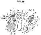
- a sixth embodiment of the present invention is shown in Fig.16.
- the sixth embodiment is basically the same in structure as the first embodiment, but is different from the first embodiment in respect of that an area X'' of the inner peripheral portion of the through-bore 9b in the second support wall Wb, which is sandwiched between the opposite ends of the first groove g 1 , is disposed to correspond to that portion A of the rocker arm body 2 to which a compressing load is applied during lifting operation provided by the cams C 1 and C 2 .
- the other construction is the same as in the first embodiment and hence, components or portions corresponding to those in the first embodiment are designated by the same reference characters as in the first embodiment.
- a portion B sandwiched between the roller shaft 7 and the rocker shaft 3 at the rear of the connecting line O has a relatively smaller burden of load, because mainly a tensile load is applied to the portion B.
- the wall thickness of the portion receiving a larger compressing load during the lifting operation provided by the cams C 1 and C 2 can be ensured at a large value to the utmost and hence, the compressing load can be received stably, despite the provision of the first groove g 1 .
- a phantom plane Z interconnecting the axis of the roller shaft 7 and rotational axes of the cams C 1 and C 2 is disposed to pass through that area X'' of the inner peripheral portion of the through-bore 9b in the second support wall Wb, which is sandwiched between the opposite ends of the first groove g 1 .
- a struck load is applied substantially along the phantom plane Z from the cams C 1 and C 2 through the roller R to the roller shaft 7 (the through-bore 9b in the support wall Wb), and that site of the cam follower body 2 which is closer to the phantom plane Z, e.g., that site of the inner peripheral portion of each of the through-bores 9a and 9b in the support walls Wa and Wb which is in the vicinity of the phantom plane Z, is a stress-concentrated site.
- the first groove g 1 can be defined to keep out of the stress-concentrated site, because the area X'' passes through the phantom plane Z, as described above.
- the reduction in rigidity and strength of such site is inhibited despite the provision of the first groove g 1 , and this is particularly convenient when the cam follower body 2 is formed of an aluminum-based metal material.
- the phantom plane Z passes a central portion of the area X'' and hence, the reduction in rigidity and strength of the stress-concentrated site is inhibited further effectively.
- a seventh embodiment of the present invention is shown in Fig.17.
- the seventh embodiment is basically the same in structure as the first embodiment, but entire opposite end faces Lf of a circlip L are formed flat. Moreover, the end faces Lf are inclined at a predetermined angle ⁇ to approach each other to a more extent at an outer location in a diametrical direction of a circlip L with respect to a phantom plane D extending radiately from an axis O of the roller shaft 7 toward the end of the circlip L.
- opposite inner end faces Gf of the hollow portion G opposed to the end faces Lf are formed flat faces (likewise inclined with respect to the phantom plane D) parallel to the opposite end faces Lf of the circlip L, respectively.
- each of the end faces of the circlip L and each of the inner end faces Gf of the hollow portion G opposed in parallel to the end faces Lf can be brought into face contact with each other with a sufficient wide contact area and hence, are brought into proper engagement with each other to exhibit a sufficient rotation-preventing effect.
- the surface pressure of contact between the end faces is alleviated effectively, which is extremely effective for a reduction in wear of the contact portions (i.e., the end faces Lf of the circlip and the inner end faces of the hollow portion G).
- each of the inner end faces Gf of the hollow portion G is extended long diametrically outwards past an outer peripheral edge portion Lfe of that end face Lf of the circlip L, which is opposed to the inner end face Gf.
- Such extension end is smoothly connected to an end edge of an arcuate groove r defined in a depressed manner in a bottom surface of the end of the first groove g 1 .
- a V-shaped recess corresponding to the edge portion Lfe on the outer peripheral side of the end face Lf of the circlip L (such a recess is liable to be a starting point for concentration of a stress) is not defined in the inner end face of the first groove g 1 . Therefore, it is possible to effectively prevent the generation of fissures and cracks in the inner end face of the first groove g 1 due to the abutment of the inner end face against the edge portion Lfe.
- a step of cutting the first groove g 1 in the through-bore in the second support wall Wb in the rocker arm body 2 having the above-described structure is similar to that in the first embodiment (see Fig.4).
- a cutter such as an end mill
- the direction of feeding the cutter is set, so that the opposite inner end faces Gf are formed into flat faces inclined at only a predetermined angle ⁇ with respect to the phantom plane D.
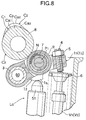
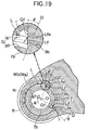
- FIG.9 An eighth embodiment of the present invention is shown in Fig.9.
- This embodiment has an arrangement similar to that in the seventh embodiment, except that the end faces Lf of a circlip L as a resilient fastener are inclined in a direction opposite to that in the seventh embodiment (i.e., at only a predetermined angle ⁇ to become farther from each other at an outer location in a diametrical direction of the circlip L with respect to the phantom plane D).
- ⁇ a predetermined angle
- a metal material for forming the roller shaft 7 is selected, so that the roller shaft 7 itself has sufficient rigidity and strength.
- at least a portion of the roller shaft 7 may be subjected to a special hardening treatment such as a high-frequency hardening and carburizing hardening, as shown in Figs.20 to 22.
- the inner surface of the second groove g 2 in the outer peripheral surface of the roller shaft 7 has been subjected to a special hardening treatment such as a high-frequency hardening and a carburizing hardening.
- a special hardening treatment such as a high-frequency hardening and a carburizing hardening.
- the wear of the inner surface of the groove g 2 due to the vibration or sliding movement of the resilient fastener L within the second groove g 2 is reduced effectively, and a slip-off effect provided by the fastener L is maintained well over a long period of time.
- the rocker arm body 2 as the cam follower body can be formed of any metal material enabling a required rigidity and strength to be ensured, such as an iron-based metal material, an aluminum-based metal material and the like.
- the formation of the rocker arm body from an aluminum-based metal material can largely contributes to a reduction in weight of the rocker arm and moreover, a reduction in inertial mass.
- an aluminum alloy material and an aluminum material are included in the aluminum-based metal material.
- the circlip L as the resilient fastener is mounted in the C-shaped groove g 1 , g 2 having the shape corresponding to the circlip, so that not only the axial relative movement but also the relative rotation of the roller shaft 7 relative to the support walls Wa and Wb can be limited.
- the groove g 1 , g 2 may be endless annular in shape, so that only the axial relative movement of the roller shaft 7 may be limited.
- roller shaft 7 is formed into the hollow cylindrical shape in the embodiments, but in the second feature (claim 17) of the present invention, the roller shaft 7 may be formed into a solid columnar shape.
- the switching pin of the connection switch-over mechanism M may be formed so that it can be slid outside the roller shaft 7. Additionally, the direction of sliding movement of the switching pin may be parallel or not parallel to the roller shaft.
- valve operating system shown in each of the first, second, fourth, seventh and eighth embodiments is designed, so that the intake valves V 1 and V 2 are operatively connected to the two cam followers 1 1 and 1 2 , whereby the valve operating characteristics for the valves V 1 and V 2 may be switched over between an individual operating mode corresponding to the two cams C 1 and C 2 and a common operating mode corresponding to the high-lift cam C 2 .
- the intake valve V may be operatively connected to only one of the two cam followers 1 1 and 1 2 , so that the valve operating characteristic may be switched over between an operating mode suitable for the high-speed operation and an operating mode suitable for the low-speed operation.
- the second intake valve V 2 is stopped during operation of the engine at the low speed in the third and fifth embodiments, but the second intake valve V 2 may be opened and closed in the valve operating mode corresponding to the low-speed operation without being stopped.
- the cam corresponding to the third rocker arm 1 3 may be changed from the stopping cam C 2 to the low-speed cam.
- the present invention is carried out for the intake valves V 1 to V 3 as the engine valves, but in place of, or in addition to this arrangement, the present invention may be carried out for exhaust valves as engine valves.
- valve operating system shown in each of the embodiments is designed, so that the circlip L as the resilient fastener is brought into engagement into the first groove g 1 in the through-bore 9b in the support wall Wb by inserting the roller shaft 7 into the through-bore 9b in the support wall Wb in the state in which the circlip L has been resiliently deformed in the shrunk manner in the second groove g 2 in the roller shaft 7.
- the C-shaped resilient circlip L may be brought into engagement into the second groove g 2 in the roller shaft 7 by inserting the roller shaft 7 into the through-bore 9b in the support wall Wb in the state in which the C-shaped resilient circlip L has been resiliently deformed in the shrunk manner in the first groove g 1 of the through-bore 9b in the support wall Wb.
- valve operating system shown in each of the seventh and eighth embodiments is designed, so that the directions of inclination of the opposite end faces Lf of the circlip L as the resilient fastener with respect to the phantom plane D are opposite from each other. According to the present invention, however, the directions of inclination of the opposite end faces Lf may be the same as each other.
- each cam follower includes a cam follower body having a pair of support walls integrally provided thereon and arranged in parallel to sandwich a roller therebetween, and a hollow roller shaft which is fitted and supported at outer peripheries of its opposite ends in through-bores in the support walls, and which has the roller rotatably carried at its intermediate portion.
- a first groove is defined in an outer peripheral surface of the through-bore in one support wall to extend circumferentially of the through-bore
- a second groove is defined in an outer peripheral surface of the roller shaft at its one end corresponding to the first groove.
- a C-shaped resilient fastener is mounted in the first and second grooves and is capable of engaging with inner surfaces of the grooves astride them.
- the switching pin is slidably fitted to inner peripheral surfaces of the roller shafts of adjacent cam followers.
- the roller shaft of the rollered cam follower can simply be fixed to the support wall of the cam follower body without caulking equipment, and a protrusion for fixing the roller shaft is not created on an outer surface of the support wall.
- the roller shaft is also used as a portion of a cam follower connecting mechanism. The roller can be rotated smoothly on an outer peripheral surface of the roller shaft, and the switching pin can be slid smoothly on an inner peripheral surface of the roller shaft.
Landscapes
- Engineering & Computer Science (AREA)
- Mechanical Engineering (AREA)
- General Engineering & Computer Science (AREA)
- Valve Device For Special Equipments (AREA)
- Valve-Gear Or Valve Arrangements (AREA)
- Gears, Cams (AREA)
- Transmission Devices (AREA)
Applications Claiming Priority (2)
| Application Number | Priority Date | Filing Date | Title |
|---|---|---|---|
| JP22031198 | 1998-08-04 | ||
| JP22031198A JP3526757B2 (ja) | 1998-08-04 | 1998-08-04 | 内燃機関用動弁装置 |
Publications (3)
| Publication Number | Publication Date |
|---|---|
| EP0978637A2 true EP0978637A2 (de) | 2000-02-09 |
| EP0978637A3 EP0978637A3 (de) | 2000-05-10 |
| EP0978637B1 EP0978637B1 (de) | 2005-01-26 |
Family
ID=16749163
Family Applications (1)
| Application Number | Title | Priority Date | Filing Date |
|---|---|---|---|
| EP99115261A Expired - Lifetime EP0978637B1 (de) | 1998-08-04 | 1999-08-02 | Ventilsteuerungseinrichtung für einem Brennkraftmaschine |
Country Status (7)
| Country | Link |
|---|---|
| US (1) | US6318315B1 (de) |
| EP (1) | EP0978637B1 (de) |
| JP (1) | JP3526757B2 (de) |
| CN (1) | CN1130496C (de) |
| CA (1) | CA2279485C (de) |
| DE (1) | DE69923390T2 (de) |
| TW (1) | TW399121B (de) |
Cited By (3)
| Publication number | Priority date | Publication date | Assignee | Title |
|---|---|---|---|---|
| EP1113151A3 (de) * | 1999-12-28 | 2002-07-24 | Honda Giken Kogyo Kabushiki Kaisha | Ventilsteuerungseinrichtung in einer Brennkraftmaschine |
| EP2546480A1 (de) * | 2010-03-12 | 2013-01-16 | NSK Ltd. | Nockenkugellager |
| WO2022111854A3 (en) * | 2020-11-30 | 2022-07-07 | Eaton Intelligent Power Limited | Switchable rocker arm |
Families Citing this family (19)
| Publication number | Priority date | Publication date | Assignee | Title |
|---|---|---|---|---|
| JP3843207B2 (ja) * | 2000-10-04 | 2006-11-08 | 田中精密工業株式会社 | 内燃機関の動弁装置 |
| DE10155825A1 (de) * | 2001-11-14 | 2003-05-22 | Ina Schaeffler Kg | Schlepphebel eines Ventiltriebs einer Brennkraftmaschine |
| DE102004012142A1 (de) * | 2004-03-12 | 2005-09-29 | Ina-Schaeffler Kg | Hebel für die Ventilsteuerung einer Kolbenmaschine |
| US7415954B2 (en) * | 2005-04-26 | 2008-08-26 | Chrysler Llc | Rocker shaft arrangement for an engine |
| US7530338B2 (en) * | 2005-04-26 | 2009-05-12 | Chrysler Llc | Valvetrain system for an engine |
| US20080110652A1 (en) * | 2006-11-14 | 2008-05-15 | Wan-Fu Wen | Method of Detecting Nail Storage State |
| JP4813399B2 (ja) * | 2007-02-23 | 2011-11-09 | 株式会社オティックス | 可変動弁機構 |
| DE102007037746B4 (de) * | 2007-08-10 | 2022-06-15 | Mercedes-Benz Group AG | Brennkraftmaschinenventiltriebumschaltvorrichtung |
| JP4993034B2 (ja) * | 2009-03-06 | 2012-08-08 | トヨタ自動車株式会社 | 内燃機関の可変動弁装置 |
| CN102345477B (zh) * | 2010-08-04 | 2015-10-07 | 光阳工业股份有限公司 | 引擎汽门推动件构造 |
| EP2653673A1 (de) * | 2012-04-19 | 2013-10-23 | Eaton S.r.l. | Schaltbarer Kipphebel |
| JP2014001652A (ja) * | 2012-06-15 | 2014-01-09 | Ntn Corp | ローラ軸、および転がり軸受構造 |
| TWI641754B (zh) * | 2014-09-17 | 2018-11-21 | 光陽工業股份有限公司 | Variable lift rocker device |
| DE102017009541A1 (de) | 2017-10-13 | 2019-04-18 | Daimler Ag | Ventiltrieb für eine Brennkraftmaschine eines Kraftfahrzeugs |
| GB2570859A (en) * | 2017-12-08 | 2019-08-14 | Eaton Srl | Apparatus for actuating a latching arrangement |
| DE102018207458A1 (de) * | 2018-05-15 | 2019-11-21 | Mahle International Gmbh | Lageranordnung einer Nockenrolle eines Ventiltriebs |
| CN108758048A (zh) * | 2018-08-26 | 2018-11-06 | 杭州龙颜激光技术有限公司 | 自动关闭式阀门装置及燃气设备 |
| JP2020056357A (ja) * | 2018-10-02 | 2020-04-09 | 日立オートモティブシステムズ株式会社 | 内燃機関のバルブタイミング制御装置 |
| CN118375501A (zh) * | 2024-04-30 | 2024-07-23 | 江苏卓联精密机械有限公司 | 发动机摇臂制动装置及发动机 |
Citations (2)
| Publication number | Priority date | Publication date | Assignee | Title |
|---|---|---|---|---|
| DE19536090A1 (de) * | 1995-09-28 | 1997-04-03 | Schaeffler Waelzlager Kg | Brennkraftmaschine mit einem Hebeltrieb zur gleichzeitigen Beaufschlagung von zumindest zwei Gaswechselventilen |
| EP0826867A1 (de) * | 1996-08-29 | 1998-03-04 | Honda Giken Kogyo Kabushiki Kaisha | Ventiltrieb in einer Brennkraftmaschine |
Family Cites Families (12)
| Publication number | Priority date | Publication date | Assignee | Title |
|---|---|---|---|---|
| GB1290691A (de) * | 1969-01-23 | 1972-09-27 | ||
| US4655176A (en) * | 1985-12-05 | 1987-04-07 | Kevin A. Sheehan | Adjustable ratio roller rocker for internal combustion engines |
| WO1987007323A1 (en) * | 1986-05-21 | 1987-12-03 | Bennett Automotive Technology Pty. Ltd. | Engines for use with gaseous fuels |
| US4829948A (en) * | 1986-12-27 | 1989-05-16 | Honda Giken Kogyo Kabushiki Kaisha | Valve operating device for internal combustion engine |
| US4807574A (en) * | 1986-12-27 | 1989-02-28 | Honda Giken Kogyo Kabushiki Kaisha | Valve operating device for internal combustion engine |
| US4762096A (en) * | 1987-09-16 | 1988-08-09 | Eaton Corporation | Engine valve control mechanism |
| JP3319794B2 (ja) * | 1993-01-18 | 2002-09-03 | 本田技研工業株式会社 | 内燃機関のsohc型動弁装置 |
| DE69408959T2 (de) * | 1993-12-24 | 1998-07-02 | Honda Motor Co Ltd | Ventiltriebanordnung für Brennkraftmaschine |
| GB9401248D0 (en) * | 1994-01-24 | 1994-03-23 | Lotus Car | Cam mechanisms |
| JP3333667B2 (ja) * | 1995-08-09 | 2002-10-15 | 本田技研工業株式会社 | Sohc型エンジンの動弁装置 |
| JP3366196B2 (ja) * | 1996-11-19 | 2003-01-14 | 本田技研工業株式会社 | 内燃機関の動弁装置 |
| US5954018A (en) * | 1997-05-08 | 1999-09-21 | Joshi; Vasant Mukund | Mode selective internal combustion engine |
-
1998
- 1998-08-04 JP JP22031198A patent/JP3526757B2/ja not_active Expired - Fee Related
-
1999
- 1999-07-30 TW TW088113066A patent/TW399121B/zh not_active IP Right Cessation
- 1999-07-30 US US09/363,653 patent/US6318315B1/en not_active Expired - Fee Related
- 1999-08-02 EP EP99115261A patent/EP0978637B1/de not_active Expired - Lifetime
- 1999-08-02 DE DE69923390T patent/DE69923390T2/de not_active Expired - Lifetime
- 1999-08-03 CA CA002279485A patent/CA2279485C/en not_active Expired - Fee Related
- 1999-08-04 CN CN99111994A patent/CN1130496C/zh not_active Expired - Fee Related
Patent Citations (2)
| Publication number | Priority date | Publication date | Assignee | Title |
|---|---|---|---|---|
| DE19536090A1 (de) * | 1995-09-28 | 1997-04-03 | Schaeffler Waelzlager Kg | Brennkraftmaschine mit einem Hebeltrieb zur gleichzeitigen Beaufschlagung von zumindest zwei Gaswechselventilen |
| EP0826867A1 (de) * | 1996-08-29 | 1998-03-04 | Honda Giken Kogyo Kabushiki Kaisha | Ventiltrieb in einer Brennkraftmaschine |
Cited By (4)
| Publication number | Priority date | Publication date | Assignee | Title |
|---|---|---|---|---|
| EP1113151A3 (de) * | 1999-12-28 | 2002-07-24 | Honda Giken Kogyo Kabushiki Kaisha | Ventilsteuerungseinrichtung in einer Brennkraftmaschine |
| EP2546480A1 (de) * | 2010-03-12 | 2013-01-16 | NSK Ltd. | Nockenkugellager |
| EP2546480A4 (de) * | 2010-03-12 | 2014-06-25 | Nsk Ltd | Nockenkugellager |
| WO2022111854A3 (en) * | 2020-11-30 | 2022-07-07 | Eaton Intelligent Power Limited | Switchable rocker arm |
Also Published As
| Publication number | Publication date |
|---|---|
| US6318315B1 (en) | 2001-11-20 |
| TW399121B (en) | 2000-07-21 |
| CA2279485A1 (en) | 2000-02-04 |
| DE69923390T2 (de) | 2005-06-30 |
| JP3526757B2 (ja) | 2004-05-17 |
| CA2279485C (en) | 2004-06-29 |
| CN1245245A (zh) | 2000-02-23 |
| EP0978637A3 (de) | 2000-05-10 |
| CN1130496C (zh) | 2003-12-10 |
| EP0978637B1 (de) | 2005-01-26 |
| JP2000045737A (ja) | 2000-02-15 |
| DE69923390D1 (de) | 2005-03-03 |
Similar Documents
| Publication | Publication Date | Title |
|---|---|---|
| EP0978637B1 (de) | Ventilsteuerungseinrichtung für einem Brennkraftmaschine | |
| DE102006057246B4 (de) | Mechanischer Stößel insbesondere für eine Kraftstoffpumpe einer Brennkraftmaschine, mit umgebogenen Laschen zur Abstützung des Bolzens der Antriebsrolle | |
| US7007652B2 (en) | Variable duration valve timing camshaft | |
| EP0297904A2 (de) | Vorrichtung zum Verändern des Kompressionsverhältnisses für Brennkraftmaschinen | |
| DE4190087C2 (de) | Ventilbetätigungsvorrichtung | |
| US8807106B2 (en) | Camshaft | |
| EP0512698A1 (de) | Verstellbare Ventilvorrichtung für eine Brennkraftmaschine | |
| EP0179581A2 (de) | Ventilantrieb mit variablen Steuerzeiten | |
| EP0563574B1 (de) | Ventilantrieb für eine Brennkraftmaschine | |
| US5438754A (en) | Method of making a valve lifter for engine | |
| EP3914811A1 (de) | Kipphebelanordnung mit spielverwaltung für zylinderabschaltung und motorbremskonfiguration | |
| AT505380B1 (de) | Dekompressor für einen verbrennungsmotor | |
| DE102004012800A1 (de) | Ventilbetätigungsvorrichtung für Verbrennungsmotoren | |
| JP2000240412A (ja) | 内燃機関の動弁装置 | |
| JPS6316112A (ja) | 内燃機関における休止機構付き動弁機構 | |
| JP2001234720A (ja) | 内燃機関の可変動弁装置 | |
| US6640760B1 (en) | Camshaft rearranging device | |
| CA1080628A (en) | Internal-combustion engine | |
| JP2002106309A (ja) | ローラ式カムフォロア装置 | |
| JP4267806B2 (ja) | 可変動弁機構 | |
| JP3269587B2 (ja) | エンジンのバルブタイミング制御装置 | |
| JP3320046B2 (ja) | 内燃機関の動弁装置 | |
| JP2782386B2 (ja) | 内燃機関の動弁機構用ローラ付ロッカアーム | |
| JP2001140610A (ja) | 直打式動弁機構 | |
| JP2001140609A (ja) | バルブリフタの回り止め機構 |
Legal Events
| Date | Code | Title | Description |
|---|---|---|---|
| PUAI | Public reference made under article 153(3) epc to a published international application that has entered the european phase |
Free format text: ORIGINAL CODE: 0009012 |
|
| AK | Designated contracting states |
Kind code of ref document: A2 Designated state(s): DE GB |
|
| AX | Request for extension of the european patent |
Free format text: AL;LT;LV;MK;RO;SI |
|
| PUAL | Search report despatched |
Free format text: ORIGINAL CODE: 0009013 |
|
| AK | Designated contracting states |
Kind code of ref document: A3 Designated state(s): AT BE CH CY DE DK ES FI FR GB GR IE IT LI LU MC NL PT SE |
|
| AX | Request for extension of the european patent |
Free format text: AL;LT;LV;MK;RO;SI |
|
| 17P | Request for examination filed |
Effective date: 20001107 |
|
| AKX | Designation fees paid |
Free format text: DE GB |
|
| 17Q | First examination report despatched |
Effective date: 20030422 |
|
| GRAP | Despatch of communication of intention to grant a patent |
Free format text: ORIGINAL CODE: EPIDOSNIGR1 |
|
| GRAS | Grant fee paid |
Free format text: ORIGINAL CODE: EPIDOSNIGR3 |
|
| GRAA | (expected) grant |
Free format text: ORIGINAL CODE: 0009210 |
|
| AK | Designated contracting states |
Kind code of ref document: B1 Designated state(s): DE GB |
|
| REG | Reference to a national code |
Ref country code: GB Ref legal event code: FG4D |
|
| REF | Corresponds to: |
Ref document number: 69923390 Country of ref document: DE Date of ref document: 20050303 Kind code of ref document: P |
|
| PLBE | No opposition filed within time limit |
Free format text: ORIGINAL CODE: 0009261 |
|
| STAA | Information on the status of an ep patent application or granted ep patent |
Free format text: STATUS: NO OPPOSITION FILED WITHIN TIME LIMIT |
|
| 26N | No opposition filed |
Effective date: 20051027 |
|
| PGFP | Annual fee paid to national office [announced via postgrant information from national office to epo] |
Ref country code: GB Payment date: 20090729 Year of fee payment: 11 |
|
| PGFP | Annual fee paid to national office [announced via postgrant information from national office to epo] |
Ref country code: DE Payment date: 20100728 Year of fee payment: 12 |
|
| GBPC | Gb: european patent ceased through non-payment of renewal fee |
Effective date: 20100802 |
|
| PG25 | Lapsed in a contracting state [announced via postgrant information from national office to epo] |
Ref country code: GB Free format text: LAPSE BECAUSE OF NON-PAYMENT OF DUE FEES Effective date: 20100802 |
|
| REG | Reference to a national code |
Ref country code: DE Ref legal event code: R119 Ref document number: 69923390 Country of ref document: DE Effective date: 20120301 |
|
| PG25 | Lapsed in a contracting state [announced via postgrant information from national office to epo] |
Ref country code: DE Free format text: LAPSE BECAUSE OF NON-PAYMENT OF DUE FEES Effective date: 20120301 |