EP0978485B1 - Forehearth feeder tube lift system - Google Patents
Forehearth feeder tube lift system Download PDFInfo
- Publication number
- EP0978485B1 EP0978485B1 EP99114381A EP99114381A EP0978485B1 EP 0978485 B1 EP0978485 B1 EP 0978485B1 EP 99114381 A EP99114381 A EP 99114381A EP 99114381 A EP99114381 A EP 99114381A EP 0978485 B1 EP0978485 B1 EP 0978485B1
- Authority
- EP
- European Patent Office
- Prior art keywords
- feeder tube
- support arm
- melting furnace
- feeder
- glass melting
- Prior art date
- Legal status (The legal status is an assumption and is not a legal conclusion. Google has not performed a legal analysis and makes no representation as to the accuracy of the status listed.)
- Expired - Lifetime
Links
Images


Classifications
-
- C—CHEMISTRY; METALLURGY
- C03—GLASS; MINERAL OR SLAG WOOL
- C03B—MANUFACTURE, SHAPING, OR SUPPLEMENTARY PROCESSES
- C03B7/00—Distributors for the molten glass; Means for taking-off charges of molten glass; Producing the gob, e.g. controlling the gob shape, weight or delivery tact
- C03B7/08—Feeder spouts, e.g. gob feeders
- C03B7/084—Tube mechanisms
-
- Y—GENERAL TAGGING OF NEW TECHNOLOGICAL DEVELOPMENTS; GENERAL TAGGING OF CROSS-SECTIONAL TECHNOLOGIES SPANNING OVER SEVERAL SECTIONS OF THE IPC; TECHNICAL SUBJECTS COVERED BY FORMER USPC CROSS-REFERENCE ART COLLECTIONS [XRACs] AND DIGESTS
- Y10—TECHNICAL SUBJECTS COVERED BY FORMER USPC
- Y10T—TECHNICAL SUBJECTS COVERED BY FORMER US CLASSIFICATION
- Y10T292/00—Closure fasteners
- Y10T292/08—Bolts
- Y10T292/0801—Multiple
- Y10T292/0848—Swinging
- Y10T292/0849—Operating means
- Y10T292/0851—Cam and lever
-
- Y—GENERAL TAGGING OF NEW TECHNOLOGICAL DEVELOPMENTS; GENERAL TAGGING OF CROSS-SECTIONAL TECHNOLOGIES SPANNING OVER SEVERAL SECTIONS OF THE IPC; TECHNICAL SUBJECTS COVERED BY FORMER USPC CROSS-REFERENCE ART COLLECTIONS [XRACs] AND DIGESTS
- Y10—TECHNICAL SUBJECTS COVERED BY FORMER USPC
- Y10T—TECHNICAL SUBJECTS COVERED BY FORMER US CLASSIFICATION
- Y10T292/00—Closure fasteners
- Y10T292/20—Clamps
- Y10T292/205—Ring
- Y10T292/212—With expanding or contracting means
- Y10T292/216—Toggle lever
-
- Y—GENERAL TAGGING OF NEW TECHNOLOGICAL DEVELOPMENTS; GENERAL TAGGING OF CROSS-SECTIONAL TECHNOLOGIES SPANNING OVER SEVERAL SECTIONS OF THE IPC; TECHNICAL SUBJECTS COVERED BY FORMER USPC CROSS-REFERENCE ART COLLECTIONS [XRACs] AND DIGESTS
- Y10—TECHNICAL SUBJECTS COVERED BY FORMER USPC
- Y10T—TECHNICAL SUBJECTS COVERED BY FORMER US CLASSIFICATION
- Y10T292/00—Closure fasteners
- Y10T292/20—Clamps
- Y10T292/225—Cam-operating means
Definitions
- This invention relates to a glass melting furnace forehearth installation including a feeder tube assembly for a feeder bowl of a glass melting furnace forehearth. More particularly, this invention relates to a clamp down system for releasably clamping the feeder tube in its operating position.
- U.S. Patent 5,718,741 discloses a forehearth for cooling a stream of molten glass as it flows from a glass melting furnace to a forming machine for forming the molten glass into finished products, for example, hollow glass containers of the type widely used in packaging various food, beverage and other products.
- molten glass flows downwardly through an opening, or a plurality of openings, in the bottom of a feeder bowl at an end of the forehearth that is remote from the end into which molten glass from the melting furnace flows.
- a vertically extending, refractory feeder tube is provided with its lowermost end immersed in the feeder bowl to a level slightly above the inside surface of the bottom of the feeder bowl and surrounding the opening(s) at the bottom of the feeder bowl, and the ceramic tube is caused to rotate slowly during the operation of the forehearth to ensure a proper mixing and temperature uniformity of the molten glass flowing from the feeder bowl.
- a feeder bowl refractory tube with a tube drive system of this general type is disclosed in U.S. Patent No. 5,660,610 (DiFrank).
- Other glass forehearth feeder bowl feeder tube arrangements are described in U.S. Patents 5,693,114 (Scott), 4,514,209 (Mumford), and 4,478,631 (Mumford).
- a feeder tube in apparatus of the type described is releasably held in place by a circumferentially spaced apart plurality of clamps.
- the invention is based on the problem to facilitate replacement and repair of the feeder bowl in an installation of the kind referred-to above.
- the invention is defined in claims 1 and 21.
- a feeder tube lift system employs a single actuator in connection with a support arm which is pivotable around the vertical axis of the actuator.
- the lift mechanism includes a ball screw operated by a single, multiple shaft, servo motor.
- the lift mechanism is of sufficient capacity to sustain the cantilevered feeder tube support mechanism with minimal deflection.
- Such a lift mechanism involves no, or very little, backlash in its motions, thereby permitting precise control of the elevation of the lift tube in the feeder bowl, which is important in achieving accurate control of glass gob weight in an I.S. machine glass container manufacturing operation.
- the feeder tube lift mechanism is also capable of true isolated adjustments in a horizontal plane, both along X and Y axes, and it can be moved without slide wear, thereby avoiding introduction of wobbling motion to the tube support system.
- the servo motor powered ball screw lift mechanism of the present invention is lubricated by a lubricant that is recirculated within a closed system to ensure long life for bearings of the mechanism and the ball roller nut, and avoiding lubricant leakage and the need for lubricant replacement.
- an improved clamp for releasably claming the feeder tube.
- This clamp comprises a clamping ring which in its clamping position engages a flange of the feeder tube while the feeder tube is in its operating position with respect to a rotatable support.
- Each such clamp has a variable radius cam that is rotatable about a radially extending horizontal axis to make secure contact with the clamping ring regardless of the elevation of the feeder tube, but which is capable of being swung out of interfering contact with the feeder tube to permit the feeder tube to be removed for repair or replacement after first removing the clamping ring used to engage the flange of the feeder tube.
- an improved clamp down system for clamping the feeder tube of the type employed in a glass forehearth feeder bowl is provided.
- Such clamp down system is rapidly releasable in that it does not require threaded fasteners in its design or installation.
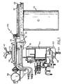
- a feeder tube assembly in which the preferred embodiment of the present invention is used is identified generally by reference numeral 20 in the drawing.
- the feeder tube assembly 20 includes a refractory feeder tube 22 which, as is shown in Fig. 3, is adapted to be inserted into a molten glass feeder bowl B at the outlet end of a generally horizontally extending molten glass cooling forehearth, otherwise not shown, which may be of conventional construction.
- the feeder tube 22 is vertically oriented in the feeder tube assembly 20, and its lowermost end is positioned slightly above the inside surface of the feeder bowl B, to thereby allow molten glass to flow through the space below the feeder tube 22 to exit through openings O at the bottom of the feeder bowl B.
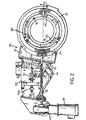
- the feeder tube 22 has an outwardly projecting flange 24 at its upper end, and the flange 24 is clamped in a clamping ring subassembly 86, Fig. 3, which is provided with lifting eyes 18, Fig. 4, and serves to support the feeder tube 22 on an inwardly projecting flange 26 of a rotatable ring subassembly 28.
- the rotatable ring subassembly 28 is cantilevered at the end of a support arm 30, and the subassembly 28 includes an upwardly facing ring gear 32, Fig.
- the support arm 30 is supported along a vertically extending axis A that extends through a handle 42, which serves to lock the support arm in a non-adjustable and a non-pivotable position as will be hereinafter described more fully.
- the support arm 30 is also adjustably supported for precisely controllable motion along the axis A oh a vertically extending servo motor powered precision linear actuator 44, Fig. 1, a cylinder portion 44a, Fig. 5, of which is secured to the framework 46 of the feeder tube assembly 20.
- the linear actuator 44 is of a type that is available from E-Drive Design, Inc. of Glastonbury, CT under the product designation Model EA2S-7.312-L/D-1836, and will be subsequently described in greater detail.
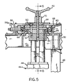
- the support arm 30 has an opening 48, Fig. 5, extending therethrough concentric with the axis A and generally concentric with the longitudinal central axis of the linear actuator 44.
- a spaced apart plurality of rods 50 extend outwardly and upwardly from the linear actuator 44 and are caused to reciprocate in unison along vertical axes by the actuation of the linear actuator 44.
- the rods 50 are non-rotatably received in a block 52 of a composite adjustment mechanism 54, which is supported on an inverted cup-shaped structure 56 that is secured to the upper surface of the support arm 30, Fig. 5.
- the adjustment mechanism 54 includes an upper plate 58, and the support arm 30 is moveable relative to the upper plate 58 along opposed spaced apart slot 60 in the structure 56, which extend generally parallel to the longitudinal axis of the support arm 30 to provide for precisely controllable adjustment of the support arm 30, and thereby of the feeder tube 22, in the X direction.
- an adjusting screw 62 which is threadably received in the structure 56a, has an inner end that engages the upper plate 58, and the turning of the adjustment screw 62 is effective to move the support arm 30 to or fro in the X direction relative to the adjustment mechanism 54, whose position in an horizontal plane is fixed by virtue of the attachment of the linear actuator 44 to the framework 46, as described.
- the adjustment mechanism 54 also includes a lower plate 64, and the support arm 30 is moveable relative to the lower plate 64 along opposed, spaced apart slots 66 in the cup-shaped structure 56, which extend transversely of the longitudinal axis of the support arm 30, to provide for precisely controllable adjustment of the support arm 30, and thereby of the feeder tube 22, in the Y direction.
- an adjustment screw 68 which is threadably received in an extension of the upper plate 58, has an inner end that engages a boss portion 70 of the cup-shaped structure 56, and turning of the adjustment screw 68 moves the support arm to or fro in the Y direction relative to the adjustment mechanism 54.
- the support arm 30 will be frictionally prevented from moving relative to the adjustment mechanism 54, either in the X direction or the Y direction.
- an annular passage 72 is provided in the support arm 30 surrounding and extending generally concentrically of the feeder tube 22, and cooling air or other cooling fluid is caused to flow through the passage 72 from inlet and outlet lines 74, 76, respectively.
- a generally semi-cylindrical heat shield 78 is suspended form the support arm 30 at a location partly surrounding the upper end of the linear actuator 44, and between the linear actuator 44 and the feeder tube 22, to retard heating of the linear actuator 44 by heat radiated from the feeder bowl B.
- Each latch mechanism 80 comprises a lever 82, Fig. 3, with a handle portion 82a at an end thereof and an enlarged cam portion 82b at an opposed end.
- the lever 82 is pivotably connected to a support member 84 about an axis C and, when the lever extends vertically, the cam portion 82b securely engages and upper surface of the clamping ring 86 which engages the flange 24 of the feeder tube 22 to forcibly press the flange 24 into its desired operating position.
- the cam portion 82b no longer engages the ring 86, Fig. 7. In this position, the feeder tube 22 may be removed from the feeder bowl B by a simple lifting motion, using the lifting eyes 18, Figs. 2 and 14.
- the latch mechanisms 80 are moveable out of alignment with the feeder tube 22 by pivotably connecting the support member 84 to a fixed structure 88 about an axis D.
- the support member 84 is slidable toward an enlarged area 88a of the fixed structure 88, where it can then be pivoted about the axis D out of interfering relationship with the clamping ring 86.
- the support arm 30 should be elevated so that the new feeder tube 20 does not contact the feeder bowl B.
- the pivoting of the support arm 30 about the axis A is done when it is desired to replace a feeder bowl B.
- the feeder tube 22 is then hoisted from the subassembly 28.
- the upper plate 58 of the adjustment mechanism 54 is pivotable with respect to the lower plate 64, after removal of an alignment pin 114 that circumferencially aligns the upper plate 58, the lower plate 64 and the block 52 with respect to one another during the operation of the feeder tube assembly 20.
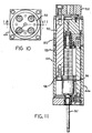
- the linear actuator 44 is powered by an a.c. servo motor 90, which is coaxially connected to the actuator 44, though it is contemplated that the connection can be by way of parallel axes with a V-belt or other drive extending therebetween.
- an assembly including the actuator 44 and the servo motor 90 is available from E-Drive Design of Glastonbury, CT, as heretofore described.
- the motor 90 has a hollow output shaft 92.
- the hollow output shaft of the motor 90 is slipped onto an input shaft 94 of the linear actuator 44 (Figs. 8 and 11), which has an internal ball screw drive 96.
- the ball screw drive 96 translates rotary motion of the shaft 92 into linear motion of an annular member 98, either to or fro depending on the direction of rotation of the shaft 92.
- the annular member 98 may be manually positioned by turning a lever 102, which is fixed to the shaft 92.
- the shaft 92 extends to a level below the motor 90, actually below the level of an arcuate heat shield 100 that protects the motor 90 from thermal radiation from the feeder bowl B, and the lever 102 extends outwardly from the shaft 92.
- the lever 102 has a handle 104 projecting downwardly therefrom, at a location radially outwardly of the shaft 92, and the shaft 92 may be turned by manually engaging the handle 104 and using it to turn the lever 102.
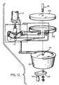
- the motor 90 is provided with an annular brake 106 that rotates with the shaft 92, and the brake 106 is selectively engageable by a double-ended constricting band 108.
- the band 108 when in its non-constricting mode, does not engage the brake 106 and provides no braking effect in such mode.
- the band 108 can be selectively tightened by the actuation of a pneumatic cylinder 110 acting through a linkage system 112, and, when the cylinder 110 is retracted, as shown in Fig. 12, the band 108 will be constricted to engage the brake 106, thus retarding turning action of the shaft 92, 94 and thereby locking the platform 30 in a desired elevation.
- the linear actuator 44 requires constant lubrication in service, and to that end a plurality of lubricating oil inlet lines 116, 118, 120, 122, 124, 126 and 128 (Fig. 4) to deliver lubricating oil from a common source (not shown) to various locations of the linear actuator 44. These locations include inlets 130, 132 (Fig. 11) of the cylinder 44a of the linear actuator 44 and each of the four (4) rods 50 (Fig. 6) that extend therefrom.
- the lubricating oil is collected at the bottom of the cylinder 44a and returned to the source for recycling, by way of a return line 134 (Fig.
- the lubricating system is a closed system that provides adequate lubrication for all moving surfaces while simultaneously minimizing lubricant losses in a hot and relatively inaccessible environment and serving to conserve a produce derived from expensive and irreplaceable natural resources.
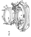
- Figs. 13 and 14 elements that differ from, but correspond in function to, elements of the embodiment of Fig. 1-12 are identified by 200 series reference numerals, the last two digits of which are the two digits of the corresponding element of the embodiment of Figs. 1-12.
- Fig. 13 illustrates a latch mechanism 280, and three such latch mechanisms 280 are illustrated in Fig. 14 in circumferentially spaced apart relationship to one another.
- Each latch mechanism 280 comprises a lever 282 with a handle portion 282a at an end thereof and an enlarged cam portion 282b at an opposed end, the handle portion 282a extending from a position that is between the ends of the cam portion 282b whereas the handle portion 82a of the lever 80 of the embodiment of Fig. 7 is aligned with an end of the cam portion 82b.
- the cam portion 282b of the lever 282 has a profile that is more universally applicable to various installations than is the profile of the cam portion 82b of the lever 82 because of variations in the thickness of the flange portion 24 of the feeder tube 22 from installation to installation.
- the lever 282 is pivotally connected to a support member 84 about an axis and when the lever 282 extends vertically, the cam portion 282b securely engages a recessed bottom in a notch 286a of a clamping ring 286, which engages the flange 24 of the feeder tube 22 to forcibly press the flange 24 into its desired operating position.
- the use of the notch 286a in the clamping ring 286 facilitates better engagement of the clamping ring 286 by the cam portion 282b of the lever 282, and it also facilitates easier release of the clamping action of the lever 280 when it is desired to change the feeder tube 22 when the lever 282 is pivoted to a horizontal orientation, the cam portion 282b no longer engages the clamping ring 286.
- the clamping ring 286 may be lifted out of position, as is shown in phantom in Fig. 14, to thereupon permit the feeder tube 22 to be lifted out of position, it first being necessary to move each of the latch-mechanisms 280 out of interfering alignment with the clamping with the clamping ring 286 and the feeder tube 22. This is done by sliding the support member 84 to the enlarged area 88a of the fixed structure 88 and then by pivoting the support member 84 about the axis D out of interfering relationship with the clamping ring 286.
Landscapes
- Chemical & Material Sciences (AREA)
- Engineering & Computer Science (AREA)
- Materials Engineering (AREA)
- Organic Chemistry (AREA)
- Re-Forming, After-Treatment, Cutting And Transporting Of Glass Products (AREA)
- Vertical, Hearth, Or Arc Furnaces (AREA)
- Transmission Devices (AREA)
- Tunnel Furnaces (AREA)
- Glass Melting And Manufacturing (AREA)
- Clamps And Clips (AREA)
- Automatic Assembly (AREA)
- Resistance Heating (AREA)
- Manufacture Of Electron Tubes, Discharge Lamp Vessels, Lead-In Wires, And The Like (AREA)
Priority Applications (2)
| Application Number | Priority Date | Filing Date | Title |
|---|---|---|---|
| DK03010110T DK1331205T3 (da) | 1998-08-07 | 1999-07-22 | Låseindretning til et forhærdtilförselsrörshejsesystem |
| EP20030010110 EP1331205B1 (en) | 1998-08-07 | 1999-07-22 | Latch mechanism for a forehearth feeder tube lift system |
Applications Claiming Priority (4)
| Application Number | Priority Date | Filing Date | Title |
|---|---|---|---|
| US287882 | 1994-08-09 | ||
| US130313 | 1998-08-07 | ||
| US09/130,313 US6151918A (en) | 1998-08-07 | 1998-08-07 | Forehearth feeder tube lift system |
| US09/287,882 US6212910B1 (en) | 1998-08-07 | 1999-04-07 | Forehearth feeder tube clamp down system |
Related Child Applications (2)
| Application Number | Title | Priority Date | Filing Date |
|---|---|---|---|
| EP20030010110 Division EP1331205B1 (en) | 1998-08-07 | 1999-07-22 | Latch mechanism for a forehearth feeder tube lift system |
| EP03010110.9 Division-Into | 2003-05-05 |
Publications (3)
| Publication Number | Publication Date |
|---|---|
| EP0978485A2 EP0978485A2 (en) | 2000-02-09 |
| EP0978485A3 EP0978485A3 (en) | 2000-08-16 |
| EP0978485B1 true EP0978485B1 (en) | 2003-09-17 |
Family
ID=26828361
Family Applications (2)
| Application Number | Title | Priority Date | Filing Date |
|---|---|---|---|
| EP99114381A Expired - Lifetime EP0978485B1 (en) | 1998-08-07 | 1999-07-22 | Forehearth feeder tube lift system |
| EP20030010110 Expired - Lifetime EP1331205B1 (en) | 1998-08-07 | 1999-07-22 | Latch mechanism for a forehearth feeder tube lift system |
Family Applications After (1)
| Application Number | Title | Priority Date | Filing Date |
|---|---|---|---|
| EP20030010110 Expired - Lifetime EP1331205B1 (en) | 1998-08-07 | 1999-07-22 | Latch mechanism for a forehearth feeder tube lift system |
Country Status (20)
| Country | Link |
|---|---|
| US (1) | US6212910B1 (enExample) |
| EP (2) | EP0978485B1 (enExample) |
| JP (1) | JP4453938B2 (enExample) |
| CN (1) | CN1227169C (enExample) |
| AR (1) | AR020120A1 (enExample) |
| AT (2) | ATE250016T1 (enExample) |
| AU (1) | AU749073B2 (enExample) |
| BR (1) | BR9903560A (enExample) |
| CA (1) | CA2278041C (enExample) |
| CO (1) | CO4960681A1 (enExample) |
| CZ (1) | CZ300178B6 (enExample) |
| DE (2) | DE69911333T2 (enExample) |
| DK (2) | DK0978485T3 (enExample) |
| EE (1) | EE03960B1 (enExample) |
| ES (2) | ES2229181T3 (enExample) |
| HU (1) | HU224470B1 (enExample) |
| PE (1) | PE20000690A1 (enExample) |
| PL (1) | PL193307B1 (enExample) |
| PT (2) | PT978485E (enExample) |
| RU (1) | RU2225371C2 (enExample) |
Families Citing this family (6)
| Publication number | Priority date | Publication date | Assignee | Title |
|---|---|---|---|---|
| ITMI20010666A1 (it) * | 2001-03-29 | 2002-09-29 | S I G M A S R L | Tubo in materiale refrattario che contribuisce alla formazione di gocce di vetro fuso |
| JP4222778B2 (ja) * | 2001-12-14 | 2009-02-12 | Hoya株式会社 | ガラス成形体の製造方法および光学素子の製造方法 |
| US6758065B1 (en) * | 2002-05-31 | 2004-07-06 | Owens-Brockway Glass Container Inc. | Apparatus for centering a glass flow control tube |
| US9803695B2 (en) * | 2014-07-14 | 2017-10-31 | Life Technologies Corporation | Drive shaft locking cap and related mixing system and method |
| CN108706858B (zh) * | 2018-05-23 | 2021-01-12 | 彩虹集团有限公司 | 一种玻璃窑炉通道喉管安装和定位装置 |
| CN109014853B (zh) * | 2018-09-06 | 2020-10-27 | 芜湖全程智能科技有限公司 | 一种刹车卡钳矩形圈安装方法 |
Family Cites Families (13)
| Publication number | Priority date | Publication date | Assignee | Title |
|---|---|---|---|---|
| US1532514A (en) * | 1923-04-16 | 1925-04-07 | Illinois Pacific Glass Company | Plunger basin for glass-feeding boots |
| US1760254A (en) * | 1923-12-31 | 1930-05-27 | Hartford Empire Co | Apparatus for feeding molten glass |
| US1852218A (en) * | 1925-11-07 | 1932-04-05 | Hartford Empire Co | Method of and apparatus for feeding molten glass |
| US1843248A (en) * | 1926-04-07 | 1932-02-02 | Owens Illinois Glass Co | Method and apparatus for controlling gravity issuance of molten glass |
| NL300150A (enExample) * | 1962-12-10 | |||
| US4478631A (en) | 1983-04-06 | 1984-10-23 | Owens-Illinois, Inc. | Glass feeder heat baffle |
| US4514209A (en) | 1983-12-01 | 1985-04-30 | Owens-Illinois, Inc. | Glass feeder tube support |
| US4551163A (en) * | 1984-06-04 | 1985-11-05 | Emhart Industries, Inc. | Electronic glass feeder plunger operating mechanism |
| US4554000A (en) | 1984-09-27 | 1985-11-19 | Emhart Industries, Inc. | Molten glass spout bowl refractory tube support mechanism and method of control |
| ECSP941070A (es) | 1993-04-19 | 1995-02-27 | Owens Brockway Glass Container | Sistema de alimentacion de vidrio con orificios multiples utilizando embolos |
| DE4408953C2 (de) * | 1994-03-16 | 1996-04-04 | Deutsche Telekom Mobil | Verfahren zur Ortsbestimmung von Mobilstationen und Anordnung zur Durchführung des Verfahrens |
| US5660610A (en) * | 1994-10-24 | 1997-08-26 | Owens-Brockway Glass Container Inc. | Remotely adjustable glass feeder needle assembly |
| US5718741A (en) * | 1995-05-19 | 1998-02-17 | Owens-Brockway Glass Container Inc. | Directly cooled, side fired forehearth |
-
1999
- 1999-04-07 US US09/287,882 patent/US6212910B1/en not_active Expired - Fee Related
- 1999-07-16 HU HU9902396A patent/HU224470B1/hu not_active IP Right Cessation
- 1999-07-19 CA CA 2278041 patent/CA2278041C/en not_active Expired - Fee Related
- 1999-07-22 DE DE1999611333 patent/DE69911333T2/de not_active Expired - Lifetime
- 1999-07-22 EP EP99114381A patent/EP0978485B1/en not_active Expired - Lifetime
- 1999-07-22 PT PT99114381T patent/PT978485E/pt unknown
- 1999-07-22 ES ES03010110T patent/ES2229181T3/es not_active Expired - Lifetime
- 1999-07-22 DE DE1999620984 patent/DE69920984T2/de not_active Expired - Lifetime
- 1999-07-22 AT AT99114381T patent/ATE250016T1/de not_active IP Right Cessation
- 1999-07-22 EP EP20030010110 patent/EP1331205B1/en not_active Expired - Lifetime
- 1999-07-22 DK DK99114381T patent/DK0978485T3/da active
- 1999-07-22 AT AT03010110T patent/ATE352525T1/de not_active IP Right Cessation
- 1999-07-22 DK DK03010110T patent/DK1331205T3/da active
- 1999-07-22 PT PT03010110T patent/PT1331205E/pt unknown
- 1999-07-22 ES ES99114381T patent/ES2207897T3/es not_active Expired - Lifetime
- 1999-07-29 AU AU42355/99A patent/AU749073B2/en not_active Ceased
- 1999-07-30 CZ CZ0270899A patent/CZ300178B6/cs not_active IP Right Cessation
- 1999-08-05 EE EEP199900302A patent/EE03960B1/xx not_active IP Right Cessation
- 1999-08-05 AR ARP990103910 patent/AR020120A1/es active IP Right Grant
- 1999-08-05 PL PL334783A patent/PL193307B1/pl not_active IP Right Cessation
- 1999-08-05 CO CO99049765A patent/CO4960681A1/es unknown
- 1999-08-06 BR BR9903560A patent/BR9903560A/pt not_active IP Right Cessation
- 1999-08-06 RU RU99117173A patent/RU2225371C2/ru not_active IP Right Cessation
- 1999-08-06 PE PE1999000793A patent/PE20000690A1/es not_active Application Discontinuation
- 1999-08-09 JP JP22557399A patent/JP4453938B2/ja not_active Expired - Fee Related
- 1999-08-09 CN CNB991106008A patent/CN1227169C/zh not_active Expired - Fee Related
Also Published As
Similar Documents
| Publication | Publication Date | Title |
|---|---|---|
| EP0978485B1 (en) | Forehearth feeder tube lift system | |
| US6314761B1 (en) | Forehearth feeder tube lift system | |
| EP0176363A1 (en) | Molten glass spout bowl refractory tube support mechanism | |
| USRE28759E (en) | Molten glass gob distribution system | |
| US3721544A (en) | Molten glass gob distribution system | |
| LV13185B (en) | Forehearth feeder tube lift system cross-reference to related application | |
| CN110465582A (zh) | 光学镀膜伞弧面开孔模具架 | |
| JP3158096B2 (ja) | 空気冷却式プッシャーバー支持体を備えた徐冷窯ローダー | |
| MXPA99006878A (en) | System of elevation of the pipe of feeding of an antecri | |
| US3239326A (en) | Tube mechanism for glass gob feeder | |
| JPH07196328A (ja) | ガラス製品製造装置におけるバッフル取りつけ手段 | |
| CN2236499Y (zh) | 通用型热处理装置 | |
| EP0087275A1 (en) | Shear frame mounting and positioning mechanism | |
| LT5291B (lt) | Maitinimo kanalo tiekimo vamzdžio kėlimo sistema | |
| JP4301607B2 (ja) | 反転・ネックリングホルダ機構 | |
| JP2000063124A5 (enExample) | ||
| CA2237380C (en) | Lehr loader with air cooled pusher bar support | |
| SI21744A (sl) | Predpečični dodajalno cevni dvižni sistem | |
| CN220322002U (zh) | 一种高温搅拌升降炉 | |
| SK277837B6 (en) | Mixing device, especially into doser of channel of parison | |
| GB2150554A (en) | Glass feeder tube support | |
| US20050022559A1 (en) | Gob distributor for a glass forming machine | |
| CN120943511A (zh) | 一种玻璃料滴制备装置及制备方法 | |
| JPH03210941A (ja) | 鋳造炉 | |
| JPH0559849B2 (enExample) |
Legal Events
| Date | Code | Title | Description |
|---|---|---|---|
| PUAI | Public reference made under article 153(3) epc to a published international application that has entered the european phase |
Free format text: ORIGINAL CODE: 0009012 |
|
| AK | Designated contracting states |
Kind code of ref document: A2 Designated state(s): AT BE CH CY DE DK ES FI FR GB GR IE IT LI LU MC NL PT SE |
|
| AX | Request for extension of the european patent |
Free format text: AL;LT;LV;MK;RO;SI |
|
| PUAL | Search report despatched |
Free format text: ORIGINAL CODE: 0009013 |
|
| AK | Designated contracting states |
Kind code of ref document: A3 Designated state(s): AT BE CH CY DE DK ES FI FR GB GR IE IT LI LU MC NL PT SE |
|
| AX | Request for extension of the european patent |
Free format text: AL;LT;LV;MK;RO;SI |
|
| 17P | Request for examination filed |
Effective date: 20010126 |
|
| AKX | Designation fees paid |
Free format text: AT BE CH CY DE DK ES FI FR GB GR IE IT LI LU MC NL PT SE |
|
| 17Q | First examination report despatched |
Effective date: 20020710 |
|
| GRAH | Despatch of communication of intention to grant a patent |
Free format text: ORIGINAL CODE: EPIDOS IGRA |
|
| GRAH | Despatch of communication of intention to grant a patent |
Free format text: ORIGINAL CODE: EPIDOS IGRA |
|
| GRAA | (expected) grant |
Free format text: ORIGINAL CODE: 0009210 |
|
| AK | Designated contracting states |
Kind code of ref document: B1 Designated state(s): AT BE CH CY DE DK ES FI FR GB GR IE IT LI LU MC NL PT SE |
|
| PG25 | Lapsed in a contracting state [announced via postgrant information from national office to epo] |
Ref country code: CY Free format text: LAPSE BECAUSE OF FAILURE TO SUBMIT A TRANSLATION OF THE DESCRIPTION OR TO PAY THE FEE WITHIN THE PRESCRIBED TIME-LIMIT Effective date: 20030917 |
|
| REG | Reference to a national code |
Ref country code: GB Ref legal event code: FG4D |
|
| REG | Reference to a national code |
Ref country code: SE Ref legal event code: TRGR |
|
| REG | Reference to a national code |
Ref country code: CH Ref legal event code: EP |
|
| REF | Corresponds to: |
Ref document number: 69911333 Country of ref document: DE Date of ref document: 20031023 Kind code of ref document: P |
|
| REG | Reference to a national code |
Ref country code: IE Ref legal event code: FG4D |
|
| REG | Reference to a national code |
Ref country code: DK Ref legal event code: T3 |
|
| REG | Reference to a national code |
Ref country code: CH Ref legal event code: NV Representative=s name: AVV. FRANCO PAGANI |
|
| APBP | Date of receipt of notice of appeal recorded |
Free format text: ORIGINAL CODE: EPIDOSNNOA2O |
|
| REG | Reference to a national code |
Ref country code: GR Ref legal event code: EP Ref document number: 20030405109 Country of ref document: GR |
|
| APBQ | Date of receipt of statement of grounds of appeal recorded |
Free format text: ORIGINAL CODE: EPIDOSNNOA3O |
|
| APBP | Date of receipt of notice of appeal recorded |
Free format text: ORIGINAL CODE: EPIDOSNNOA2O |
|
| APBQ | Date of receipt of statement of grounds of appeal recorded |
Free format text: ORIGINAL CODE: EPIDOSNNOA3O |
|
| ET | Fr: translation filed | ||
| REG | Reference to a national code |
Ref country code: ES Ref legal event code: FG2A Ref document number: 2207897 Country of ref document: ES Kind code of ref document: T3 |
|
| PLBE | No opposition filed within time limit |
Free format text: ORIGINAL CODE: 0009261 |
|
| STAA | Information on the status of an ep patent application or granted ep patent |
Free format text: STATUS: NO OPPOSITION FILED WITHIN TIME LIMIT |
|
| PG25 | Lapsed in a contracting state [announced via postgrant information from national office to epo] |
Ref country code: MC Free format text: LAPSE BECAUSE OF NON-PAYMENT OF DUE FEES Effective date: 20040731 |
|
| APAY | Date of receipt of notice of appeal deleted |
Free format text: ORIGINAL CODE: EPIDOSDNOA2O |
|
| APBA | Date of receipt of statement of grounds of appeal deleted |
Free format text: ORIGINAL CODE: EPIDOSDNOA3O |
|
| 26N | No opposition filed |
Effective date: 20040618 |
|
| APAA | Appeal reference recorded |
Free format text: ORIGINAL CODE: EPIDOS REFN |
|
| APBU | Appeal procedure closed |
Free format text: ORIGINAL CODE: EPIDOSNNOA9O |
|
| APAH | Appeal reference modified |
Free format text: ORIGINAL CODE: EPIDOSCREFNO |
|
| PGFP | Annual fee paid to national office [announced via postgrant information from national office to epo] |
Ref country code: LU Payment date: 20070705 Year of fee payment: 9 |
|
| PGFP | Annual fee paid to national office [announced via postgrant information from national office to epo] |
Ref country code: DK Payment date: 20080617 Year of fee payment: 10 |
|
| PGFP | Annual fee paid to national office [announced via postgrant information from national office to epo] |
Ref country code: IE Payment date: 20080718 Year of fee payment: 10 Ref country code: AT Payment date: 20080616 Year of fee payment: 10 |
|
| PGFP | Annual fee paid to national office [announced via postgrant information from national office to epo] |
Ref country code: BE Payment date: 20080730 Year of fee payment: 10 |
|
| PGFP | Annual fee paid to national office [announced via postgrant information from national office to epo] |
Ref country code: GR Payment date: 20080704 Year of fee payment: 10 |
|
| PGFP | Annual fee paid to national office [announced via postgrant information from national office to epo] |
Ref country code: FI Payment date: 20090624 Year of fee payment: 11 |
|
| BERE | Be: lapsed |
Owner name: *OWENS-BROCKWAY GLASS CONTAINER INC. Effective date: 20090731 |
|
| REG | Reference to a national code |
Ref country code: DK Ref legal event code: EBP |
|
| REG | Reference to a national code |
Ref country code: IE Ref legal event code: MM4A |
|
| PG25 | Lapsed in a contracting state [announced via postgrant information from national office to epo] |
Ref country code: LU Free format text: LAPSE BECAUSE OF NON-PAYMENT OF DUE FEES Effective date: 20080722 Ref country code: BE Free format text: LAPSE BECAUSE OF NON-PAYMENT OF DUE FEES Effective date: 20090731 Ref country code: AT Free format text: LAPSE BECAUSE OF NON-PAYMENT OF DUE FEES Effective date: 20090722 |
|
| PG25 | Lapsed in a contracting state [announced via postgrant information from national office to epo] |
Ref country code: IE Free format text: LAPSE BECAUSE OF NON-PAYMENT OF DUE FEES Effective date: 20090722 Ref country code: DK Free format text: LAPSE BECAUSE OF NON-PAYMENT OF DUE FEES Effective date: 20090731 |
|
| PG25 | Lapsed in a contracting state [announced via postgrant information from national office to epo] |
Ref country code: GR Free format text: LAPSE BECAUSE OF NON-PAYMENT OF DUE FEES Effective date: 20100204 |
|
| REG | Reference to a national code |
Ref country code: CH Ref legal event code: PFA Owner name: OWENS-BROCKWAY GLASS CONTAINER INC. Free format text: OWENS-BROCKWAY GLASS CONTAINER INC.#ONE SEA GATE#TOLEDO, OHIO 43666 (US) -TRANSFER TO- OWENS-BROCKWAY GLASS CONTAINER INC.#ONE SEA GATE#TOLEDO, OHIO 43666 (US) |
|
| PG25 | Lapsed in a contracting state [announced via postgrant information from national office to epo] |
Ref country code: FI Free format text: LAPSE BECAUSE OF NON-PAYMENT OF DUE FEES Effective date: 20100722 |
|
| PGFP | Annual fee paid to national office [announced via postgrant information from national office to epo] |
Ref country code: SE Payment date: 20130729 Year of fee payment: 15 Ref country code: PT Payment date: 20130122 Year of fee payment: 15 Ref country code: NL Payment date: 20130726 Year of fee payment: 15 Ref country code: ES Payment date: 20130726 Year of fee payment: 15 Ref country code: CH Payment date: 20130729 Year of fee payment: 15 Ref country code: DE Payment date: 20130729 Year of fee payment: 15 |
|
| PGFP | Annual fee paid to national office [announced via postgrant information from national office to epo] |
Ref country code: GB Payment date: 20130729 Year of fee payment: 15 Ref country code: FR Payment date: 20130717 Year of fee payment: 15 |
|
| PGFP | Annual fee paid to national office [announced via postgrant information from national office to epo] |
Ref country code: IT Payment date: 20130726 Year of fee payment: 15 |
|
| REG | Reference to a national code |
Ref country code: PT Ref legal event code: MM4A Free format text: LAPSE DUE TO NON-PAYMENT OF FEES Effective date: 20150122 |
|
| REG | Reference to a national code |
Ref country code: DE Ref legal event code: R119 Ref document number: 69911333 Country of ref document: DE |
|
| REG | Reference to a national code |
Ref country code: NL Ref legal event code: V1 Effective date: 20150201 |
|
| REG | Reference to a national code |
Ref country code: CH Ref legal event code: PL |
|
| REG | Reference to a national code |
Ref country code: SE Ref legal event code: EUG |
|
| GBPC | Gb: european patent ceased through non-payment of renewal fee |
Effective date: 20140722 |
|
| PG25 | Lapsed in a contracting state [announced via postgrant information from national office to epo] |
Ref country code: NL Free format text: LAPSE BECAUSE OF NON-PAYMENT OF DUE FEES Effective date: 20150201 |
|
| REG | Reference to a national code |
Ref country code: FR Ref legal event code: ST Effective date: 20150331 |
|
| PG25 | Lapsed in a contracting state [announced via postgrant information from national office to epo] |
Ref country code: PT Free format text: LAPSE BECAUSE OF NON-PAYMENT OF DUE FEES Effective date: 20150122 Ref country code: CH Free format text: LAPSE BECAUSE OF NON-PAYMENT OF DUE FEES Effective date: 20140731 Ref country code: IT Free format text: LAPSE BECAUSE OF NON-PAYMENT OF DUE FEES Effective date: 20140722 Ref country code: DE Free format text: LAPSE BECAUSE OF NON-PAYMENT OF DUE FEES Effective date: 20150203 Ref country code: LI Free format text: LAPSE BECAUSE OF NON-PAYMENT OF DUE FEES Effective date: 20140731 |
|
| REG | Reference to a national code |
Ref country code: DE Ref legal event code: R119 Ref document number: 69911333 Country of ref document: DE Effective date: 20150203 |
|
| PG25 | Lapsed in a contracting state [announced via postgrant information from national office to epo] |
Ref country code: SE Free format text: LAPSE BECAUSE OF NON-PAYMENT OF DUE FEES Effective date: 20140723 Ref country code: GB Free format text: LAPSE BECAUSE OF NON-PAYMENT OF DUE FEES Effective date: 20140722 Ref country code: FR Free format text: LAPSE BECAUSE OF NON-PAYMENT OF DUE FEES Effective date: 20140731 |
|
| REG | Reference to a national code |
Ref country code: ES Ref legal event code: FD2A Effective date: 20160127 |
|
| PG25 | Lapsed in a contracting state [announced via postgrant information from national office to epo] |
Ref country code: ES Free format text: LAPSE BECAUSE OF NON-PAYMENT OF DUE FEES Effective date: 20140723 |