EP0977708B1 - Procede et dispositif pour convertir de l'acide sulfhydrique en soufre elementaire - Google Patents
Procede et dispositif pour convertir de l'acide sulfhydrique en soufre elementaire Download PDFInfo
- Publication number
- EP0977708B1 EP0977708B1 EP98924145A EP98924145A EP0977708B1 EP 0977708 B1 EP0977708 B1 EP 0977708B1 EP 98924145 A EP98924145 A EP 98924145A EP 98924145 A EP98924145 A EP 98924145A EP 0977708 B1 EP0977708 B1 EP 0977708B1
- Authority
- EP
- European Patent Office
- Prior art keywords
- oxygen
- combustion chamber
- gas
- hydrogen
- process according
- Prior art date
- Legal status (The legal status is an assumption and is not a legal conclusion. Google has not performed a legal analysis and makes no representation as to the accuracy of the status listed.)
- Expired - Lifetime
Links
Images
Classifications
-
- C—CHEMISTRY; METALLURGY
- C01—INORGANIC CHEMISTRY
- C01B—NON-METALLIC ELEMENTS; COMPOUNDS THEREOF; METALLOIDS OR COMPOUNDS THEREOF NOT COVERED BY SUBCLASS C01C
- C01B17/00—Sulfur; Compounds thereof
- C01B17/02—Preparation of sulfur; Purification
- C01B17/04—Preparation of sulfur; Purification from gaseous sulfur compounds including gaseous sulfides
- C01B17/0404—Preparation of sulfur; Purification from gaseous sulfur compounds including gaseous sulfides by processes comprising a dry catalytic conversion of hydrogen sulfide-containing gases, e.g. the Claus process
- C01B17/0413—Preparation of sulfur; Purification from gaseous sulfur compounds including gaseous sulfides by processes comprising a dry catalytic conversion of hydrogen sulfide-containing gases, e.g. the Claus process characterised by the combustion step
- C01B17/0421—Multistage combustion
-
- Y—GENERAL TAGGING OF NEW TECHNOLOGICAL DEVELOPMENTS; GENERAL TAGGING OF CROSS-SECTIONAL TECHNOLOGIES SPANNING OVER SEVERAL SECTIONS OF THE IPC; TECHNICAL SUBJECTS COVERED BY FORMER USPC CROSS-REFERENCE ART COLLECTIONS [XRACs] AND DIGESTS
- Y02—TECHNOLOGIES OR APPLICATIONS FOR MITIGATION OR ADAPTATION AGAINST CLIMATE CHANGE
- Y02P—CLIMATE CHANGE MITIGATION TECHNOLOGIES IN THE PRODUCTION OR PROCESSING OF GOODS
- Y02P20/00—Technologies relating to chemical industry
- Y02P20/10—Process efficiency
- Y02P20/129—Energy recovery, e.g. by cogeneration, H2recovery or pressure recovery turbines
Definitions
- the invention relates to a process for converting hydrogen sulfide (H 2 S) into elemental sulfur (S).
- sulfur is required either in elementary form or in the form of sulfuric acid. But sulfur is highly toxic in the form of sulfur dioxide (SO 2 ) or as hydrogen sulfide. There are therefore maximum permissible emission limit values for these sulfur compounds, which are being tightened worldwide.
- Contain fossil fuels such as natural gas, coal, oil sands, oil shale and petroleum organic and inorganic sulfur compounds. It is necessary to do this To remove sulfur compounds or in harmless sulfur compounds convert. For the removal of sulfur compounds from fuels and Combustion products exist in a variety of physical and chemical Conversion processes.
- the sulfur compounds are burned in the Power plant as sulfur dioxide through flue gas desulfurization using milk of lime absorbed and converted into calcium sulfite. Through oxidation in the exhaust gas Residual oxygen contained is the end product of gypsum.
- liquid fuels such as diesel fuel or light heating oil
- maximum permissible sulfur levels are prescribed. Because desulfurization the smoke gases after a possible combustion, for example in engines no longer realizable. The desulfurization of these fuels is carried out in the Refineries carried out.
- the sulfur compounds present in the crude oil are found in the distillate, the heavy oil fraction being the highest Has sulfur concentrations.
- Desulphurization takes place with the help of gaseous hydrogen (H 2 ).
- the organic sulfur compounds are converted into hydrogen sulfide.
- the hydrogen sulfide which is present in the gas mixture with hydrogen and other hydrocarbons, is washed out in amine scrubbers as Claus or hydrogen sulfide gas with concentrations of up to 90% by volume of hydrogen sulfide.
- Hydrogen sulfide is also produced in the acid water stripper columns.
- hydrogen sulfide is present as an aqueous condensate and is stripped out as an acid water stripping gas (SWS gas) with up to 50 vol.% Hydrogen sulfide.
- SWS gas acid water stripping gas
- up to 50% by volume of ammonia (NH 3 ) can be contained, which is formed by the decomposition of organic nitrogen compounds.
- Hydrogen sulfide also comes in different concentrations in the Associated petroleum gas and in natural gas with a share of up to 30 vol.% And in the exhaust gas of sewage treatment plants with a share of up to 5 vol.% hydrogen sulfide.
- the conversion process is the Claus process, which was developed in 1883. This The process is based on a dry oxidation process. A variety of Process variants have emerged. All process variants are based on the same basic chemical reactions and the use of a thermal and of a catalytic reactor.
- the thermal reactor consists of a combustion chamber with one burner, one Waste heat boiler and a first sulfur condenser.
- the catalytic reactor is executed in two or three stages. The steps each have a heater Catalyst bed and a sulfur condenser.
- the other associated process gases such as hydrogen, Methane, higher hydrocarbons, ammonia, water vapor, carbon dioxide, react according to their concentrations in a variety of Side reactions.
- reaction 2 The actual Claus reaction between sulfur dioxide and hydrogen sulfide, at the elemental sulfur and water vapor is formed, reaction 2. This is running in the catalyst bed.
- Elemental sulfur is also generated directly by the thermal cracking of hydrogen sulfide into sulfur and water in the combustion chamber: 3. H 2 S ⁇ H 2 + 1/2 S 2
- one third of the amount of hydrogen sulfide is usually one Mixture of Claus and acid water stripping gas, by means of the burner Combustion air is substoichiometrically burned to a third of sulfur dioxide.
- the remaining hydrogen sulfide splits thermally in the temperature range between 900 ° C and 1300 ° C in the combustion chamber in sulfur and hydrogen and becomes catalytically at temperatures between 180 ° C and 400 ° C in the elementary catalytic reactors with the unburned hydrogen sulfide Sulfur and water implemented.
- the conversion to sulfur is optimal if that Hydrogen sulfide / sulfur dioxide ratio is two to one. The optimal In practice, however, the ratio is only approximated.
- the elemental sulfur formed in the combustion chamber is after cooling the Process gas after the waste heat boiler and in the first sulfur condenser separated liquid. In the downstream catalytic reactors, this becomes cooled process gas before entering the catalysts through the upstream Use high pressure steam or heat transfer oil to heat the necessary Reaction temperature heated.
- the sulfur formed by the Claus reaction becomes also separated in liquid form in the sulfur condensers.
- the total amount of hydrogen sulfide with the Combustion air partially burned in the combustion chamber In the main stream operation, the total amount of hydrogen sulfide with the Combustion air partially burned in the combustion chamber. Through the thermal cleavage of the hydrogen sulfide in the combustion chamber is already a large proportion of sulfur deposited in the first sulfur condenser after the waste heat boiler.
- For hydrogen sulfide-rich gas is the degree of sulfur conversion at one three-stage Claus process 96 to 97%.
- Downstream tail gas treatment plants mostly Claus processes with thermal Afterburning, then make it possible by the plant capacity dependent legal limits.
- bypass operation In the case of hydrogen sulfide concentrations of less than 30% by volume, the bypass operation is also can no longer be used due to the low calorific value. The combustion then becomes unstable. In addition, the bypass operation usually requires one ammonia-free feed gas. Otherwise the catalytic converters are connected via the bypass Ammonia contaminated. In the presence of ammonia, for example when used of sour water stripping gas, the sour water stripping gas must be separated from the Clausgas are burned in the combustion chamber. These qualities of feed gas require modified variants of the Claus process.
- sulfur capacity means here the amount of sulfur produced per unit of time.
- the enrichment of the combustion air is included The easiest way to realize oxygen.
- the increased throughput of hydrogen sulfide is proportional to the amount of oxygen supplied.
- the maximum possible The amount of oxygen is determined by the permissible operating temperatures of the burner, the Waste heat and the first reactor limited.
- the combustion air is enriched with oxygen, whereby higher concentrations can be achieved with up to 100 vol.% oxygen.
- a special burner and an additional circuit fan are required for this.
- This process uses the high oxygen concentration Temperature increase in the combustion chamber and in the waste heat boiler through recirculation compensated by cold process gas. The process gas is after the first Sulfur condenser sucked in and through the burner into the combustion chamber a drop in temperature. Because of the higher Process gas quantities increase the pressure loss in the combustion chamber and in Waste heat boiler. In the downstream catalytic reactor stages Pressure loss is lower due to the reduced process gas quantities.
- the Lurgi-oxygen Claus burner is a burner that works with air, with oxygen, or can be operated with air and oxygen as the oxidation medium.
- the maximum possible oxygen concentration is approx. 80 vol.%.
- the Clausgas and that Sour water stripping gas containing ammonia is fed separately.
- the Acid water stripping gas is mixed with air in a central burner muffle the heating gas burned.
- the Claus gas is used with oxygen and air as the oxidation medium with several double concentric single burners, symmetrical around the Burner muffle are arranged, burned.
- a single burner consists of one central oxygen nozzle, a concentric Claus gas nozzle and one double concentric air nozzle.
- This arrangement creates individual ones Oxygen / hydrogen sulfide flames from colder air / hydrogen sulfide flames to be enveloped. This will change the temperature in the combustion chamber controlled. A recirculation of cold process gas to lower the temperature is not necessary even with high amounts of oxygen.
- the SURE process also uses oxygen-enriched air or 100 vol.% Oxygen is used as the oxidation medium.
- the SURE double combustion process involves the combustion of the hydrogen sulfide with two series connected, each with a waste heat boiler and one Sulfur condenser equipped combustion chambers.
- the Hydrogen sulfide gas is used with a subset of the oxygen in the first Combustion chamber burned, cooled in a waste heat boiler, in the second Combustion chamber transferred through a burner and used for the Claus reaction required amount of residual oxygen added. This division will also controls the temperature in the combustion chambers.
- the invention is therefore based on the object, the disadvantages of the prior art To overcome technology and to provide a process with which in particular the throughput and the degree of implementation of Hydrogen sulfide is improved to elemental sulfur.
- the procedure is also said to have comparatively little additional Effort can be integrated into existing Claus systems.
- the process according to the invention has the advantage that the sulfur capacity of Claus plants using oxygen or an oxygen-rich Gases is increased, with only low investment costs are necessary. Are at the same time but significantly higher oxygen concentrations or hydrogen sulfide throughputs, compared to conventional oxygenation.
- the oxygen is not only used as an oxidation medium as before, but is also used to increase the mixing energy in order to improve the mixing between oxidizing agent and feed gas in the existing combustion chamber.
- the mixing energy By increasing the mixing energy, the combustion density and thus the throughput of hydrogen sulfide can be increased.
- an additional post-combustion zone is integrated into the existing combustion chamber, which is generated by highly turbulent, self-priming oxygen jets. In this way, the process gas emerging from the combustor or the burner, partially reacted with air or premixed, is completely afterburned.
- the reactions taking place in the combustion chamber take place closer to the thermodynamic equilibrium.
- the terms “partially burn” and “afterburn” refer to stoichiometric combustion.
- oxygen instead of technically pure oxygen, which is delivered compressed by pipeline or liquefied from vacuum-insulated containers at high pressure, oxygen with a purity of 80 vol.% To 100 vol.% Oxygen content can also be used. This is preferably produced by molecular sieve adsorption plants, for example vacuum swing adsorption plants (VSA) or vacuum pressure swing adsorption plants (PVSA) directly at the consumer.
- VSA vacuum swing adsorption plants
- PVSA vacuum pressure swing adsorption plants
- the additional oxygen is not passed through the burner as before Enrichment of the combustion air metered in, but preferably by at least one or a plurality of individual nozzles at high speed blown.
- the exit speeds are from the Individual oxygen nozzles preferably in a Mach number range between 0.4 and 2.
- Mach number is the ratio of the nozzle outlet speed to understand the speed of sound of the gases. Because of the relatively high The exit velocity of the oxygen creates highly turbulent free jets suck in the surrounding combustion chamber atmosphere, mix and mix with the flammable components react. The hydrogen sulfide becomes too Burned sulfur dioxide.
- the stoichiometric hydrogen sulfide / sulfur dioxide ratio of two to one is established, for example, due to the intensive mixing. This means that the oxygen in the combustion chamber is fully converted.
- the lifetime of the first catalytic reactor is extended by the complete conversion of the oxygen. Because at reactor temperatures of 380 ° C to 550 ° C, the excess oxygen otherwise present in Claus plants reacts with the existing sulfur dioxide to form sulfur trioxide (SO3), which reacts with the catalyst pellets made of aluminum oxide according to the following reaction equation: 4. Al 2 O 3 + SO 3 ⁇ Al 2 SO 4 + O 2
- the hydrogen sulfide / sulfur dioxide free jet diffusion flames are not on the Stabilize the nozzle, but lift it off the nozzle, freely in the combustion chamber burn.
- the flame roots are removed from the oxygen nozzles relocated the combustion chamber.
- the one for an oxygen velocity according to a Mach number of one necessary oxygen absolute pressure on The nozzle outlet should preferably be 1.93 times that in the combustion chamber prevailing pressure (PBRK).
- the angle of inclination of the oxygen injection lances is preferably 45 ° to 90 ° to the direction of flow, the axes of the oxygen jets being in the Cut the central axis of the combustion chamber.
- the oxygen injection lances are included the nozzles advantageously flush or withdrawn into the inner wall of the Combustion chamber installed.
- the oxygen injection lances are preferably in Distance of approx. 0.25 of the combustion chamber diameter from the center of the Combustion chamber measured, symmetrically distributed around the circumference, installed. This will an oxygen swirl flow directed against the swirl of the main flame generated.
- the oxygen injection lances are preferably concentric, with the Oxygen nozzle is enveloped by an annular gap nozzle.
- an annular gap nozzle advantageously a protective gas with a minimum exit speed blown into the combustion chamber according to a Mach number of 0.2 in order to obtain the To cool the oxygen nozzle and to protect it against the diffusion of sulfur.
- Air, nitrogen or carbon dioxide is preferably used as the protective gas.
- Example 1 Example 2
- Example 3 Claus gas kg / h 442 603 706 SWS gas kg / h 240 259 246 Air total kg / h 1515 1222 797 Oxygen kg / h 0 71 146
- Brennschtemp. ° C 1213 1331 1415 Abhitzekesseltemp. ° C 597 617 641
- Burner temperature ° C 297 259 268 Reaktortemp. R1 ° C 355 387 395 H 2 S / SO 2 ratio 2.08
- 2.01 2.01 Sulfur capacity% 100 126 142
- X Claus gas 85 vol.%
- X SWS gas 46 vol.%
- the high combustion temperatures when using oxygen have a positive effect on the thermal cleavage and complete combustion of higher hydrocarbons and ammonia, a particularly for complete ammonia splitting and combustion Minimum temperature of 1350 ° C should be maintained.
- Due to the Missing nitrogen ballast can occur at an equivalent oxygen concentration of 40 vol.%
- the concentration of hydrogen sulfide gas in the gas mixture used can be reduced to 20% by volume of hydrogen sulfide.
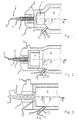
- FIGS. 1 and 2 are a burner and the adjoining part of the combustion chamber a Claus system, the burner shown in FIGS. 1 and 2 additionally has a combustor.
- Fig. 1 shows the burner (1), which with a 3-fold concentric tube (2) an inner pilot tube (3) via the middle tube (4) and a heating gas outer tube (5) the Claus / SWS gas are supplied. Air passes through line (6) passed into the burner (1). The combustion takes place in the combustor (7) and there subsequent combustion chamber (8).
- a nozzle (9) Oxygen introduced into the combustion chamber at high speed.
- the lance for introducing the oxygen (10) in their front area consists of a double-concentric tube, with the inner tube (11) of oxygen and a protective gas via the outer tube (12) is initiated to cool the nozzle (9).
- the angle “ ⁇ ” here denotes the Angle of inclination of the oxygen lance in relation to the flow direction (R).
- the angle "According to the invention, ⁇ lies in the range of 45 ° ( ⁇ ) and 90 ° ( ⁇ '). Connbustor (7) and Combustion chamber (8) are made in one piece here.
- Fig. 2 shows a similar embodiment as Fig. 1, wherein combustor (7) and combustion chamber (8) are separated from each other.
- the burner (1) has a triple concentric tube (2) with an inner tube (3) for pilot gas, a middle tube (4) for heating gas and an outer one Pipe (5) for Claus / SWS gas. Air is supplied via line (6).
- a combustor (7) is arranged in front of the combustion chamber (8).
- Oxygen and a protective gas are supplied via a double-concentric tube, the oxygen in the inner tube (11) and the protective gas in the outer tube (12).
- the oxygen lance is arranged in the device at an angle ⁇ to ⁇ '(45 ° to 90 °) with respect to the flow direction (R).
- the combustion chamber (8) connects directly to the burner (1) of the Claus plant on.
- the pilot gas is in via a separate pipe (13) initiated the burner.
Claims (14)
- Procédé pour l'obtention de soufre élémentaire par combustion d'hydrogène sulfuré ou d'un gaz contenant de l'hydrogène sulfuré, en particulier par le procédé Claus, dans lequel l'hydrogène sulfuré ou le gaz contenant de l'hydrogène sulfuré est partiellement brûlé par un premier dispositif dans un brûleur dans une chambre de combustion avec addition d'air en tant que milieu d'oxydation, de l'oxygène ou un gaz contenant de l'oxygène étant envoyé à la chambre de combustion par au moins un second dispositif supplémentaire, de sorte que l'hydrogène sulfuré ou le gaz contenant de l'hydrogène sulfuré est soumis à une post-combustion et ensuite envoyé à une chaudière de récupération, puis à un ou plusieurs réacteurs, le gaz contenant de l'oxygène contenant de 80 % en volume à 100 % en volume d'oxygène.
- Procédé selon la revendication 1, dans lequel l'oxygène ou le gaz contenant de l'oxygène est injecté par une ou plusieurs buses individuelles.
- Procédé selon la revendication 1 ou 2, dans lequel la vitesse d'entrée de l'oxygène ou du gaz contenant de l'oxygène dans la chambre de combustion se situe dans la plage d'un nombre de Mach compris entre 0,4 et 2, ce qui, en raison de la forte turbulence, augmente le mélange entre l'oxygène, l'air de combustion et le gaz de processus contenant de l'hydrogène sulfuré.
- Procédé selon l'une quelconque des revendications 1 à 3, dans lequel l'oxygène ou le gaz contenant de l'oxygène pénètre dans la chambre de combustion sous un angle, mesuré dans le sens du flux, de 45° à 90°.
- Procédé selon l'une quelconque des revendications 1 à 4, dans lequel, dans le cas d'un processus comportant une torsion de la flamme principale dans la chambre de combustion, est engendré un flux de torsion de l'oxygène ou du gaz contenant de l'oxygène, qui est orienté dans le sens contraire de la torsion de la flamme principale.
- Procédé selon l'une quelconque des revendications 1 à 5, dans lequel le point d'entrée de l'oxygène ou du gaz contenant de l'oxygène dans la chambre de combustion est refroidi et est protégé contre une pénétration du soufre par diffusion.
- Procédé selon la revendication 6, dans lequel pour le refroidissement on envoie en outre à la chambre de combustion un gaz protecteur dans la zone du point d'entrée de l'oxygène ou du gaz contenant de l'oxygène dans la chambre de combustion.
- Procédé selon la revendication 7, dans lequel on utilise en tant que gaz protecteur de l'air, de l'azote ou du dioxyde de carbone.
- Procédé selon la revendication 7 ou 8, dans lequel la vitesse d'entrée du gaz protecteur dans la chambre de combustion présente au moins le nombre de Mach 0,2, de sorte que le mélange turbulent entre l'oxygène, l'air de combustion et le gaz de processus contenant de l'hydrogène sulfuré est augmenté additionnellement.
- Procédé selon l'une quelconque des revendications 1 à 9, dans lequel la quantité d'oxygène envoyé conformément à la stoechiométrie de la réaction de Claus est réglée de manière que l'oxygène et l'air de combustion réagissent totalement avec l'hydrogène sulfuré et les autres gaz combustibles afin qu'aucun oxygène en excès ne soit présent après la chambre de combustion.
- Procédé selon l'une quelconque des revendications 1 à 10, dans lequel la quantité d'oxygène envoyé conformément à la réaction de Claus est réglée de telle sorte que le rapport hydrogène sulfuré/anhydride sulfureux correspond à la valeur théorique 2.
- Procédé selon l'une quelconque des revendications 1 à 11, dans lequel la quantité d'oxygène envoyé conformément à la stoechiométrie de la réaction de Claus est réglée de telle sorte que les températures maximales dans le brûleur/l'unité de combustion sont de 250°C/1200°C et la température maximale dans la chambre de combustion est de 1500°C, de sorte que le transfert de chaleur sur la paroi de la chambre de combustion est amélioré et la température maximale dans la chaudière de récupération est de 670°C.
- Procédé selon l'une quelconque des revendications 1 à 12, dans lequel la concentration équivalente d'oxygène est comprise entre 21 et 40 % en volume.
- Procédé selon l'une quelconque des revendications 1 à 13, dans lequel la contamination de l'hydrogène sulfuré dans le gaz utilisé est d'au moins 20 % en volume.
Applications Claiming Priority (3)
| Application Number | Priority Date | Filing Date | Title |
|---|---|---|---|
| DE19718261 | 1997-04-30 | ||
| DE19718261A DE19718261A1 (de) | 1997-04-30 | 1997-04-30 | Verfahren und Vorrichtung zur Umwandlung von Schwefelwasserstoff in elementaren Schwefel |
| PCT/EP1998/002297 WO1998049098A1 (fr) | 1997-04-30 | 1998-04-17 | Procede et dispositif pour convertir de l'acide sulfhydrique en soufre elementaire |
Publications (2)
| Publication Number | Publication Date |
|---|---|
| EP0977708A1 EP0977708A1 (fr) | 2000-02-09 |
| EP0977708B1 true EP0977708B1 (fr) | 2004-10-20 |
Family
ID=7828220
Family Applications (1)
| Application Number | Title | Priority Date | Filing Date |
|---|---|---|---|
| EP98924145A Expired - Lifetime EP0977708B1 (fr) | 1997-04-30 | 1998-04-17 | Procede et dispositif pour convertir de l'acide sulfhydrique en soufre elementaire |
Country Status (9)
| Country | Link |
|---|---|
| US (1) | US6780392B2 (fr) |
| EP (1) | EP0977708B1 (fr) |
| AT (1) | ATE280128T1 (fr) |
| DE (2) | DE19718261A1 (fr) |
| ES (1) | ES2231986T3 (fr) |
| HR (1) | HRP980160B1 (fr) |
| PL (1) | PL191175B1 (fr) |
| WO (1) | WO1998049098A1 (fr) |
| ZA (1) | ZA983616B (fr) |
Families Citing this family (16)
| Publication number | Priority date | Publication date | Assignee | Title |
|---|---|---|---|---|
| DE19951909C2 (de) * | 1999-10-28 | 2002-01-24 | Ruhr Oel Gmbh | Verfahren zur Verbrennung von Sauerwasserstrippergas |
| GB9929330D0 (en) * | 1999-12-10 | 2000-02-02 | Boc Group Plc | Sulphur recovery |
| JP3924150B2 (ja) * | 2001-10-26 | 2007-06-06 | 三菱重工業株式会社 | ガス燃焼処理方法およびその装置 |
| US7108842B2 (en) * | 2004-01-15 | 2006-09-19 | Conocophillips Company | Process for the catalytic partial oxidation of H2S using staged addition of oxygen |
| US7416571B2 (en) * | 2005-03-09 | 2008-08-26 | Conocophillips Company | Compact mixer for the mixing of gaseous hydrocarbon and gaseous oxidants |
| US7226572B1 (en) | 2006-03-03 | 2007-06-05 | Conocophillips Company | Compact sulfur recovery plant and process |
| US7501111B2 (en) | 2006-08-25 | 2009-03-10 | Conoco Phillips Company | Increased capacity sulfur recovery plant and process for recovering elemental sulfur |
| CN102369394A (zh) * | 2009-03-17 | 2012-03-07 | T.D.E.回收技术有限公司 | 热解反应器用的进料设备和进料方法 |
| DE102009018911A1 (de) * | 2009-04-28 | 2011-01-20 | Lurgi Gmbh | Verfahren zum Herstellen von Prozessgas für das Claus-Verfahren |
| CA2843041C (fr) | 2013-02-22 | 2017-06-13 | Anschutz Exploration Corporation | Methode et systeme d'extraction de sulfure d'hydrogene de petrole acide et d'eau acide |
| US9364773B2 (en) | 2013-02-22 | 2016-06-14 | Anschutz Exploration Corporation | Method and system for removing hydrogen sulfide from sour oil and sour water |
| US11440815B2 (en) | 2013-02-22 | 2022-09-13 | Anschutz Exploration Corporation | Method and system for removing hydrogen sulfide from sour oil and sour water |
| US9708196B2 (en) | 2013-02-22 | 2017-07-18 | Anschutz Exploration Corporation | Method and system for removing hydrogen sulfide from sour oil and sour water |
| RU2530096C1 (ru) * | 2013-02-27 | 2014-10-10 | Открытое акционерное общество "Гипрогазоочистка" | Способ получения серы из сероводородсодержащего газа методом клауса и каталитический реактор для его осуществления |
| RU2711363C1 (ru) * | 2015-06-17 | 2020-01-16 | Чайна Петролеум Энд Кемикал Корпорейшн | Способ обработки отработанной кислоты после алкилирования и устройство для осуществления указанного способа |
| JP7041745B2 (ja) * | 2017-11-28 | 2022-03-24 | ハルドール・トプサー・アクチエゼルスカベット | 硫黄および硫酸の製造方法 |
Family Cites Families (9)
| Publication number | Priority date | Publication date | Assignee | Title |
|---|---|---|---|---|
| FR2424875A1 (fr) * | 1978-05-02 | 1979-11-30 | Elf Aquitaine | Procede de production de soufre a partir de deux gaz acides renfermant h2s et dont un seul contient nh3 |
| FR2509192A1 (fr) * | 1981-07-10 | 1983-01-14 | Krupp Koppers Gmbh | Procede pour eliminer, en obtenant simultanement du soufre elementaire, les eaux residuaires se formant lors de la desulfuration du gaz de cokerie avec une solution de lavage renfermant des vecteurs d'oxygene |
| GB2107450B (en) * | 1981-10-14 | 1984-11-14 | Shell Int Research | Process for combusting hydrogen sulphide-containing gases and burner for use in such a process |
| US4888162A (en) * | 1984-07-03 | 1989-12-19 | Air Products And Chemicals, Inc. | Temperature moderation with water of an oxygen enriched claus sulfur plant |
| US4632818A (en) * | 1984-10-03 | 1986-12-30 | Air Products And Chemicals, Inc. | Production of sulfur from an oxygen enriched claus system |
| WO1989012023A1 (fr) * | 1988-06-08 | 1989-12-14 | American Combustion, Inc. | Procede et appareil de recuperation de soufre a partir de gaz contenant du sulfure d'hydrogene |
| US5028409A (en) * | 1988-07-26 | 1991-07-02 | American Combustion, Inc. | Method and apparatus for recovering sulfur from gases containing hydrogen sulfide |
| GB9314212D0 (en) * | 1993-07-09 | 1993-08-18 | Boc Group Plc | A gas combuster/reactor |
| GB9419133D0 (en) * | 1994-09-19 | 1994-11-09 | Wickham Michael | A method of forming sulphur |
-
1997
- 1997-04-30 DE DE19718261A patent/DE19718261A1/de not_active Ceased
-
1998
- 1998-03-26 HR HR980160A patent/HRP980160B1/xx not_active IP Right Cessation
- 1998-04-17 DE DE59812152T patent/DE59812152D1/de not_active Expired - Lifetime
- 1998-04-17 US US09/403,081 patent/US6780392B2/en not_active Expired - Lifetime
- 1998-04-17 EP EP98924145A patent/EP0977708B1/fr not_active Expired - Lifetime
- 1998-04-17 ES ES98924145T patent/ES2231986T3/es not_active Expired - Lifetime
- 1998-04-17 PL PL336474A patent/PL191175B1/pl unknown
- 1998-04-17 WO PCT/EP1998/002297 patent/WO1998049098A1/fr active IP Right Grant
- 1998-04-17 AT AT98924145T patent/ATE280128T1/de active
- 1998-04-29 ZA ZA983616A patent/ZA983616B/xx unknown
Also Published As
| Publication number | Publication date |
|---|---|
| DE59812152D1 (de) | 2004-11-25 |
| PL336474A1 (en) | 2000-06-19 |
| ES2231986T3 (es) | 2005-05-16 |
| WO1998049098A1 (fr) | 1998-11-05 |
| HRP980160A2 (en) | 1999-02-28 |
| PL191175B1 (pl) | 2006-03-31 |
| HRP980160B1 (en) | 2005-04-30 |
| EP0977708A1 (fr) | 2000-02-09 |
| US20020031468A1 (en) | 2002-03-14 |
| US6780392B2 (en) | 2004-08-24 |
| DE19718261A1 (de) | 1998-11-05 |
| ATE280128T1 (de) | 2004-11-15 |
| ZA983616B (en) | 1998-11-02 |
Similar Documents
| Publication | Publication Date | Title |
|---|---|---|
| EP0977708B1 (fr) | Procede et dispositif pour convertir de l'acide sulfhydrique en soufre elementaire | |
| KR100608432B1 (ko) | 황화수소의 부분 산화에 의한 황화 증기 형성 방법 및 장치 | |
| DE1926629C3 (de) | Verfahren zur Beseitigung des aus Koksofengasen und ihren Kondensaten abgetrennten Ammoniaks | |
| EP2507167B1 (fr) | Procédé de fabrication d'acide sulfurique | |
| US7695701B2 (en) | Process for treating acid gas in staged furnaces with inter-stage heat recovery | |
| EP0160332B1 (fr) | Procédé pour éliminer de l'hydrogène sulfuré de gaz d'échappement et pour préparer du soufre selon le procédé Claus | |
| EP0132584B1 (fr) | Procédé et installation pour diminuer l'émission de la matière nocive dans les gaz d'échappement des installations de combustion | |
| DE2613343A1 (de) | Verfahren zur gewinnung von schwefel aus so tief 2-haltigen gasen | |
| DE10045322A1 (de) | Zerstäubungsbrenner für die thermische Spaltung von schwefelhaltigem Reststoff | |
| DE3308406C2 (fr) | ||
| DE3636024C2 (fr) | ||
| DE60012291T2 (de) | Verfahren zur Rückgewinnung von Schwefelverbindungen | |
| DE60313441T2 (de) | Partialoxidation von schwefelwasserstoff | |
| EP0496101A1 (fr) | Procédé pour traitement thermique de déchets contenant de sulfates d'ammoniac, particulièrement de déchets liquides aqueux contenant des sulfates d'ammonium | |
| DE19951909C2 (de) | Verfahren zur Verbrennung von Sauerwasserstrippergas | |
| DE3331545A1 (de) | Verfahren und anlage zum vermindern der schadstoffemission in rauchgasen von feuerungsanlagen | |
| WO2020244802A1 (fr) | Procédé et dispositif de production de soufre | |
| EP1131150B1 (fr) | Procede d'exploitation d'une installation de combustion | |
| DE3618514A1 (de) | Verfahren zum betreiben einer katalytischen stickoxidreduktionsstufe | |
| DE4419193A1 (de) | Verfahren und Vorrichtung zur Verbrennung, insbesondere Nachverbrennung von Gasen sowie zur vollständigen Zersetzung von Schadstoffen und zur Erzeugung von Abgas mit reduziertem NO¶x¶-Gehalt | |
| US20080286704A1 (en) | Method of burning a nitrogen-containing fuel | |
| DE2940321A1 (de) | Verfahren zur thermischen umwandlung von gasfoermigen und/oder fluessigen abfallstoffen | |
| DE2224233B2 (de) | Verfahren zum betreiben eines gemischt-beschickten schachtofens zum brennen vom kalkstein sowie vorrichtung zur durchfuehrung des verfahrens |
Legal Events
| Date | Code | Title | Description |
|---|---|---|---|
| PUAI | Public reference made under article 153(3) epc to a published international application that has entered the european phase |
Free format text: ORIGINAL CODE: 0009012 |
|
| 17P | Request for examination filed |
Effective date: 19991130 |
|
| AK | Designated contracting states |
Kind code of ref document: A1 Designated state(s): AT BE CH CY DE ES FI FR GB GR IT LI NL SE |
|
| AX | Request for extension of the european patent |
Free format text: RO PAYMENT 19991130;SI PAYMENT 19991130 |
|
| 17Q | First examination report despatched |
Effective date: 20000828 |
|
| RAP1 | Party data changed (applicant data changed or rights of an application transferred) |
Owner name: MESSER GRIESHEIM GMBH |
|
| GRAP | Despatch of communication of intention to grant a patent |
Free format text: ORIGINAL CODE: EPIDOSNIGR1 |
|
| GRAS | Grant fee paid |
Free format text: ORIGINAL CODE: EPIDOSNIGR3 |
|
| GRAA | (expected) grant |
Free format text: ORIGINAL CODE: 0009210 |
|
| AK | Designated contracting states |
Kind code of ref document: B1 Designated state(s): AT BE CH CY DE ES FI FR GB GR IT LI NL SE |
|
| AX | Request for extension of the european patent |
Extension state: RO SI |
|
| REG | Reference to a national code |
Ref country code: GB Ref legal event code: FG4D Free format text: NOT ENGLISH |
|
| REG | Reference to a national code |
Ref country code: CH Ref legal event code: EP |
|
| REF | Corresponds to: |
Ref document number: 59812152 Country of ref document: DE Date of ref document: 20041125 Kind code of ref document: P |
|
| PG25 | Lapsed in a contracting state [announced via postgrant information from national office to epo] |
Ref country code: SE Free format text: LAPSE BECAUSE OF FAILURE TO SUBMIT A TRANSLATION OF THE DESCRIPTION OR TO PAY THE FEE WITHIN THE PRESCRIBED TIME-LIMIT Effective date: 20050120 Ref country code: GR Free format text: LAPSE BECAUSE OF FAILURE TO SUBMIT A TRANSLATION OF THE DESCRIPTION OR TO PAY THE FEE WITHIN THE PRESCRIBED TIME-LIMIT Effective date: 20050120 |
|
| RAP2 | Party data changed (patent owner data changed or rights of a patent transferred) |
Owner name: AIR LIQUIDE DEUTSCHLAND GMBH |
|
| RAP2 | Party data changed (patent owner data changed or rights of a patent transferred) |
Owner name: AIR LIQUIDE DEUTSCHLAND GMBH |
|
| GBT | Gb: translation of ep patent filed (gb section 77(6)(a)/1977) |
Effective date: 20050224 |
|
| PG25 | Lapsed in a contracting state [announced via postgrant information from national office to epo] |
Ref country code: CY Free format text: LAPSE BECAUSE OF FAILURE TO SUBMIT A TRANSLATION OF THE DESCRIPTION OR TO PAY THE FEE WITHIN THE PRESCRIBED TIME-LIMIT Effective date: 20050417 |
|
| NLT2 | Nl: modifications (of names), taken from the european patent patent bulletin |
Owner name: AIR LIQUIDE DEUTSCHLAND GMBH |
|
| REG | Reference to a national code |
Ref country code: ES Ref legal event code: FG2A Ref document number: 2231986 Country of ref document: ES Kind code of ref document: T3 |
|
| RAP2 | Party data changed (patent owner data changed or rights of a patent transferred) |
Owner name: AIR LIQUIDE DEUTSCHLAND GMBH |
|
| PLBE | No opposition filed within time limit |
Free format text: ORIGINAL CODE: 0009261 |
|
| STAA | Information on the status of an ep patent application or granted ep patent |
Free format text: STATUS: NO OPPOSITION FILED WITHIN TIME LIMIT |
|
| NLT2 | Nl: modifications (of names), taken from the european patent patent bulletin |
Owner name: AIR LIQUIDE DEUTSCHLAND GMBH Effective date: 20050622 |
|
| 26N | No opposition filed |
Effective date: 20050721 |
|
| ET | Fr: translation filed | ||
| NLS | Nl: assignments of ep-patents |
Owner name: MESSER GROUP GMBH Effective date: 20071003 |
|
| NLT1 | Nl: modifications of names registered in virtue of documents presented to the patent office pursuant to art. 16 a, paragraph 1 |
Owner name: AIR LIQUIDE DEUTSCHLAND GMBH |
|
| PGFP | Annual fee paid to national office [announced via postgrant information from national office to epo] |
Ref country code: CH Payment date: 20080502 Year of fee payment: 11 |
|
| PGFP | Annual fee paid to national office [announced via postgrant information from national office to epo] |
Ref country code: FI Payment date: 20080411 Year of fee payment: 11 |
|
| REG | Reference to a national code |
Ref country code: CH Ref legal event code: PL |
|
| PG25 | Lapsed in a contracting state [announced via postgrant information from national office to epo] |
Ref country code: LI Free format text: LAPSE BECAUSE OF NON-PAYMENT OF DUE FEES Effective date: 20090430 Ref country code: FI Free format text: LAPSE BECAUSE OF NON-PAYMENT OF DUE FEES Effective date: 20090417 Ref country code: CH Free format text: LAPSE BECAUSE OF NON-PAYMENT OF DUE FEES Effective date: 20090430 |
|
| PGFP | Annual fee paid to national office [announced via postgrant information from national office to epo] |
Ref country code: NL Payment date: 20120413 Year of fee payment: 15 |
|
| PGFP | Annual fee paid to national office [announced via postgrant information from national office to epo] |
Ref country code: IT Payment date: 20120421 Year of fee payment: 15 |
|
| PGFP | Annual fee paid to national office [announced via postgrant information from national office to epo] |
Ref country code: AT Payment date: 20120327 Year of fee payment: 15 |
|
| REG | Reference to a national code |
Ref country code: NL Ref legal event code: V1 Effective date: 20131101 |
|
| PG25 | Lapsed in a contracting state [announced via postgrant information from national office to epo] |
Ref country code: IT Free format text: LAPSE BECAUSE OF NON-PAYMENT OF DUE FEES Effective date: 20130417 Ref country code: NL Free format text: LAPSE BECAUSE OF NON-PAYMENT OF DUE FEES Effective date: 20131101 |
|
| REG | Reference to a national code |
Ref country code: AT Ref legal event code: MM01 Ref document number: 280128 Country of ref document: AT Kind code of ref document: T Effective date: 20140417 |
|
| PG25 | Lapsed in a contracting state [announced via postgrant information from national office to epo] |
Ref country code: AT Free format text: LAPSE BECAUSE OF NON-PAYMENT OF DUE FEES Effective date: 20140417 |
|
| REG | Reference to a national code |
Ref country code: FR Ref legal event code: PLFP Year of fee payment: 19 |
|
| REG | Reference to a national code |
Ref country code: FR Ref legal event code: PLFP Year of fee payment: 20 |
|
| PGFP | Annual fee paid to national office [announced via postgrant information from national office to epo] |
Ref country code: FR Payment date: 20170313 Year of fee payment: 20 |
|
| PGFP | Annual fee paid to national office [announced via postgrant information from national office to epo] |
Ref country code: BE Payment date: 20170313 Year of fee payment: 20 |
|
| PGFP | Annual fee paid to national office [announced via postgrant information from national office to epo] |
Ref country code: ES Payment date: 20170317 Year of fee payment: 20 |
|
| PGFP | Annual fee paid to national office [announced via postgrant information from national office to epo] |
Ref country code: GB Payment date: 20170419 Year of fee payment: 20 Ref country code: DE Payment date: 20170419 Year of fee payment: 20 |
|
| REG | Reference to a national code |
Ref country code: DE Ref legal event code: R071 Ref document number: 59812152 Country of ref document: DE |
|
| REG | Reference to a national code |
Ref country code: GB Ref legal event code: PE20 Expiry date: 20180416 |
|
| REG | Reference to a national code |
Ref country code: BE Ref legal event code: MK Effective date: 20180417 |
|
| PG25 | Lapsed in a contracting state [announced via postgrant information from national office to epo] |
Ref country code: GB Free format text: LAPSE BECAUSE OF EXPIRATION OF PROTECTION Effective date: 20180416 |
|
| REG | Reference to a national code |
Ref country code: ES Ref legal event code: FD2A Effective date: 20200902 |
|
| PG25 | Lapsed in a contracting state [announced via postgrant information from national office to epo] |
Ref country code: ES Free format text: LAPSE BECAUSE OF EXPIRATION OF PROTECTION Effective date: 20180418 |