EP0977708B1 - Method and device for converting hydrogen sulfide into elemental sulfur - Google Patents
Method and device for converting hydrogen sulfide into elemental sulfur Download PDFInfo
- Publication number
- EP0977708B1 EP0977708B1 EP98924145A EP98924145A EP0977708B1 EP 0977708 B1 EP0977708 B1 EP 0977708B1 EP 98924145 A EP98924145 A EP 98924145A EP 98924145 A EP98924145 A EP 98924145A EP 0977708 B1 EP0977708 B1 EP 0977708B1
- Authority
- EP
- European Patent Office
- Prior art keywords
- oxygen
- combustion chamber
- gas
- hydrogen
- process according
- Prior art date
- Legal status (The legal status is an assumption and is not a legal conclusion. Google has not performed a legal analysis and makes no representation as to the accuracy of the status listed.)
- Expired - Lifetime
Links
Images
Classifications
-
- C—CHEMISTRY; METALLURGY
- C01—INORGANIC CHEMISTRY
- C01B—NON-METALLIC ELEMENTS; COMPOUNDS THEREOF; METALLOIDS OR COMPOUNDS THEREOF NOT COVERED BY SUBCLASS C01C
- C01B17/00—Sulfur; Compounds thereof
- C01B17/02—Preparation of sulfur; Purification
- C01B17/04—Preparation of sulfur; Purification from gaseous sulfur compounds including gaseous sulfides
- C01B17/0404—Preparation of sulfur; Purification from gaseous sulfur compounds including gaseous sulfides by processes comprising a dry catalytic conversion of hydrogen sulfide-containing gases, e.g. the Claus process
- C01B17/0413—Preparation of sulfur; Purification from gaseous sulfur compounds including gaseous sulfides by processes comprising a dry catalytic conversion of hydrogen sulfide-containing gases, e.g. the Claus process characterised by the combustion step
- C01B17/0421—Multistage combustion
-
- Y—GENERAL TAGGING OF NEW TECHNOLOGICAL DEVELOPMENTS; GENERAL TAGGING OF CROSS-SECTIONAL TECHNOLOGIES SPANNING OVER SEVERAL SECTIONS OF THE IPC; TECHNICAL SUBJECTS COVERED BY FORMER USPC CROSS-REFERENCE ART COLLECTIONS [XRACs] AND DIGESTS
- Y02—TECHNOLOGIES OR APPLICATIONS FOR MITIGATION OR ADAPTATION AGAINST CLIMATE CHANGE
- Y02P—CLIMATE CHANGE MITIGATION TECHNOLOGIES IN THE PRODUCTION OR PROCESSING OF GOODS
- Y02P20/00—Technologies relating to chemical industry
- Y02P20/10—Process efficiency
- Y02P20/129—Energy recovery, e.g. by cogeneration, H2recovery or pressure recovery turbines
Definitions
- the invention relates to a process for converting hydrogen sulfide (H 2 S) into elemental sulfur (S).
- sulfur is required either in elementary form or in the form of sulfuric acid. But sulfur is highly toxic in the form of sulfur dioxide (SO 2 ) or as hydrogen sulfide. There are therefore maximum permissible emission limit values for these sulfur compounds, which are being tightened worldwide.
- Contain fossil fuels such as natural gas, coal, oil sands, oil shale and petroleum organic and inorganic sulfur compounds. It is necessary to do this To remove sulfur compounds or in harmless sulfur compounds convert. For the removal of sulfur compounds from fuels and Combustion products exist in a variety of physical and chemical Conversion processes.
- the sulfur compounds are burned in the Power plant as sulfur dioxide through flue gas desulfurization using milk of lime absorbed and converted into calcium sulfite. Through oxidation in the exhaust gas Residual oxygen contained is the end product of gypsum.
- liquid fuels such as diesel fuel or light heating oil
- maximum permissible sulfur levels are prescribed. Because desulfurization the smoke gases after a possible combustion, for example in engines no longer realizable. The desulfurization of these fuels is carried out in the Refineries carried out.
- the sulfur compounds present in the crude oil are found in the distillate, the heavy oil fraction being the highest Has sulfur concentrations.
- Desulphurization takes place with the help of gaseous hydrogen (H 2 ).
- the organic sulfur compounds are converted into hydrogen sulfide.
- the hydrogen sulfide which is present in the gas mixture with hydrogen and other hydrocarbons, is washed out in amine scrubbers as Claus or hydrogen sulfide gas with concentrations of up to 90% by volume of hydrogen sulfide.
- Hydrogen sulfide is also produced in the acid water stripper columns.
- hydrogen sulfide is present as an aqueous condensate and is stripped out as an acid water stripping gas (SWS gas) with up to 50 vol.% Hydrogen sulfide.
- SWS gas acid water stripping gas
- up to 50% by volume of ammonia (NH 3 ) can be contained, which is formed by the decomposition of organic nitrogen compounds.
- Hydrogen sulfide also comes in different concentrations in the Associated petroleum gas and in natural gas with a share of up to 30 vol.% And in the exhaust gas of sewage treatment plants with a share of up to 5 vol.% hydrogen sulfide.
- the conversion process is the Claus process, which was developed in 1883. This The process is based on a dry oxidation process. A variety of Process variants have emerged. All process variants are based on the same basic chemical reactions and the use of a thermal and of a catalytic reactor.
- the thermal reactor consists of a combustion chamber with one burner, one Waste heat boiler and a first sulfur condenser.
- the catalytic reactor is executed in two or three stages. The steps each have a heater Catalyst bed and a sulfur condenser.
- the other associated process gases such as hydrogen, Methane, higher hydrocarbons, ammonia, water vapor, carbon dioxide, react according to their concentrations in a variety of Side reactions.
- reaction 2 The actual Claus reaction between sulfur dioxide and hydrogen sulfide, at the elemental sulfur and water vapor is formed, reaction 2. This is running in the catalyst bed.
- Elemental sulfur is also generated directly by the thermal cracking of hydrogen sulfide into sulfur and water in the combustion chamber: 3. H 2 S ⁇ H 2 + 1/2 S 2
- one third of the amount of hydrogen sulfide is usually one Mixture of Claus and acid water stripping gas, by means of the burner Combustion air is substoichiometrically burned to a third of sulfur dioxide.
- the remaining hydrogen sulfide splits thermally in the temperature range between 900 ° C and 1300 ° C in the combustion chamber in sulfur and hydrogen and becomes catalytically at temperatures between 180 ° C and 400 ° C in the elementary catalytic reactors with the unburned hydrogen sulfide Sulfur and water implemented.
- the conversion to sulfur is optimal if that Hydrogen sulfide / sulfur dioxide ratio is two to one. The optimal In practice, however, the ratio is only approximated.
- the elemental sulfur formed in the combustion chamber is after cooling the Process gas after the waste heat boiler and in the first sulfur condenser separated liquid. In the downstream catalytic reactors, this becomes cooled process gas before entering the catalysts through the upstream Use high pressure steam or heat transfer oil to heat the necessary Reaction temperature heated.
- the sulfur formed by the Claus reaction becomes also separated in liquid form in the sulfur condensers.
- the total amount of hydrogen sulfide with the Combustion air partially burned in the combustion chamber In the main stream operation, the total amount of hydrogen sulfide with the Combustion air partially burned in the combustion chamber. Through the thermal cleavage of the hydrogen sulfide in the combustion chamber is already a large proportion of sulfur deposited in the first sulfur condenser after the waste heat boiler.
- For hydrogen sulfide-rich gas is the degree of sulfur conversion at one three-stage Claus process 96 to 97%.
- Downstream tail gas treatment plants mostly Claus processes with thermal Afterburning, then make it possible by the plant capacity dependent legal limits.
- bypass operation In the case of hydrogen sulfide concentrations of less than 30% by volume, the bypass operation is also can no longer be used due to the low calorific value. The combustion then becomes unstable. In addition, the bypass operation usually requires one ammonia-free feed gas. Otherwise the catalytic converters are connected via the bypass Ammonia contaminated. In the presence of ammonia, for example when used of sour water stripping gas, the sour water stripping gas must be separated from the Clausgas are burned in the combustion chamber. These qualities of feed gas require modified variants of the Claus process.
- sulfur capacity means here the amount of sulfur produced per unit of time.
- the enrichment of the combustion air is included The easiest way to realize oxygen.
- the increased throughput of hydrogen sulfide is proportional to the amount of oxygen supplied.
- the maximum possible The amount of oxygen is determined by the permissible operating temperatures of the burner, the Waste heat and the first reactor limited.
- the combustion air is enriched with oxygen, whereby higher concentrations can be achieved with up to 100 vol.% oxygen.
- a special burner and an additional circuit fan are required for this.
- This process uses the high oxygen concentration Temperature increase in the combustion chamber and in the waste heat boiler through recirculation compensated by cold process gas. The process gas is after the first Sulfur condenser sucked in and through the burner into the combustion chamber a drop in temperature. Because of the higher Process gas quantities increase the pressure loss in the combustion chamber and in Waste heat boiler. In the downstream catalytic reactor stages Pressure loss is lower due to the reduced process gas quantities.
- the Lurgi-oxygen Claus burner is a burner that works with air, with oxygen, or can be operated with air and oxygen as the oxidation medium.
- the maximum possible oxygen concentration is approx. 80 vol.%.
- the Clausgas and that Sour water stripping gas containing ammonia is fed separately.
- the Acid water stripping gas is mixed with air in a central burner muffle the heating gas burned.
- the Claus gas is used with oxygen and air as the oxidation medium with several double concentric single burners, symmetrical around the Burner muffle are arranged, burned.
- a single burner consists of one central oxygen nozzle, a concentric Claus gas nozzle and one double concentric air nozzle.
- This arrangement creates individual ones Oxygen / hydrogen sulfide flames from colder air / hydrogen sulfide flames to be enveloped. This will change the temperature in the combustion chamber controlled. A recirculation of cold process gas to lower the temperature is not necessary even with high amounts of oxygen.
- the SURE process also uses oxygen-enriched air or 100 vol.% Oxygen is used as the oxidation medium.
- the SURE double combustion process involves the combustion of the hydrogen sulfide with two series connected, each with a waste heat boiler and one Sulfur condenser equipped combustion chambers.
- the Hydrogen sulfide gas is used with a subset of the oxygen in the first Combustion chamber burned, cooled in a waste heat boiler, in the second Combustion chamber transferred through a burner and used for the Claus reaction required amount of residual oxygen added. This division will also controls the temperature in the combustion chambers.
- the invention is therefore based on the object, the disadvantages of the prior art To overcome technology and to provide a process with which in particular the throughput and the degree of implementation of Hydrogen sulfide is improved to elemental sulfur.
- the procedure is also said to have comparatively little additional Effort can be integrated into existing Claus systems.
- the process according to the invention has the advantage that the sulfur capacity of Claus plants using oxygen or an oxygen-rich Gases is increased, with only low investment costs are necessary. Are at the same time but significantly higher oxygen concentrations or hydrogen sulfide throughputs, compared to conventional oxygenation.
- the oxygen is not only used as an oxidation medium as before, but is also used to increase the mixing energy in order to improve the mixing between oxidizing agent and feed gas in the existing combustion chamber.
- the mixing energy By increasing the mixing energy, the combustion density and thus the throughput of hydrogen sulfide can be increased.
- an additional post-combustion zone is integrated into the existing combustion chamber, which is generated by highly turbulent, self-priming oxygen jets. In this way, the process gas emerging from the combustor or the burner, partially reacted with air or premixed, is completely afterburned.
- the reactions taking place in the combustion chamber take place closer to the thermodynamic equilibrium.
- the terms “partially burn” and “afterburn” refer to stoichiometric combustion.
- oxygen instead of technically pure oxygen, which is delivered compressed by pipeline or liquefied from vacuum-insulated containers at high pressure, oxygen with a purity of 80 vol.% To 100 vol.% Oxygen content can also be used. This is preferably produced by molecular sieve adsorption plants, for example vacuum swing adsorption plants (VSA) or vacuum pressure swing adsorption plants (PVSA) directly at the consumer.
- VSA vacuum swing adsorption plants
- PVSA vacuum pressure swing adsorption plants
- the additional oxygen is not passed through the burner as before Enrichment of the combustion air metered in, but preferably by at least one or a plurality of individual nozzles at high speed blown.
- the exit speeds are from the Individual oxygen nozzles preferably in a Mach number range between 0.4 and 2.
- Mach number is the ratio of the nozzle outlet speed to understand the speed of sound of the gases. Because of the relatively high The exit velocity of the oxygen creates highly turbulent free jets suck in the surrounding combustion chamber atmosphere, mix and mix with the flammable components react. The hydrogen sulfide becomes too Burned sulfur dioxide.
- the stoichiometric hydrogen sulfide / sulfur dioxide ratio of two to one is established, for example, due to the intensive mixing. This means that the oxygen in the combustion chamber is fully converted.
- the lifetime of the first catalytic reactor is extended by the complete conversion of the oxygen. Because at reactor temperatures of 380 ° C to 550 ° C, the excess oxygen otherwise present in Claus plants reacts with the existing sulfur dioxide to form sulfur trioxide (SO3), which reacts with the catalyst pellets made of aluminum oxide according to the following reaction equation: 4. Al 2 O 3 + SO 3 ⁇ Al 2 SO 4 + O 2
- the hydrogen sulfide / sulfur dioxide free jet diffusion flames are not on the Stabilize the nozzle, but lift it off the nozzle, freely in the combustion chamber burn.
- the flame roots are removed from the oxygen nozzles relocated the combustion chamber.
- the one for an oxygen velocity according to a Mach number of one necessary oxygen absolute pressure on The nozzle outlet should preferably be 1.93 times that in the combustion chamber prevailing pressure (PBRK).
- the angle of inclination of the oxygen injection lances is preferably 45 ° to 90 ° to the direction of flow, the axes of the oxygen jets being in the Cut the central axis of the combustion chamber.
- the oxygen injection lances are included the nozzles advantageously flush or withdrawn into the inner wall of the Combustion chamber installed.
- the oxygen injection lances are preferably in Distance of approx. 0.25 of the combustion chamber diameter from the center of the Combustion chamber measured, symmetrically distributed around the circumference, installed. This will an oxygen swirl flow directed against the swirl of the main flame generated.
- the oxygen injection lances are preferably concentric, with the Oxygen nozzle is enveloped by an annular gap nozzle.
- an annular gap nozzle advantageously a protective gas with a minimum exit speed blown into the combustion chamber according to a Mach number of 0.2 in order to obtain the To cool the oxygen nozzle and to protect it against the diffusion of sulfur.
- Air, nitrogen or carbon dioxide is preferably used as the protective gas.
- Example 1 Example 2
- Example 3 Claus gas kg / h 442 603 706 SWS gas kg / h 240 259 246 Air total kg / h 1515 1222 797 Oxygen kg / h 0 71 146
- Brennschtemp. ° C 1213 1331 1415 Abhitzekesseltemp. ° C 597 617 641
- Burner temperature ° C 297 259 268 Reaktortemp. R1 ° C 355 387 395 H 2 S / SO 2 ratio 2.08
- 2.01 2.01 Sulfur capacity% 100 126 142
- X Claus gas 85 vol.%
- X SWS gas 46 vol.%
- the high combustion temperatures when using oxygen have a positive effect on the thermal cleavage and complete combustion of higher hydrocarbons and ammonia, a particularly for complete ammonia splitting and combustion Minimum temperature of 1350 ° C should be maintained.
- Due to the Missing nitrogen ballast can occur at an equivalent oxygen concentration of 40 vol.%
- the concentration of hydrogen sulfide gas in the gas mixture used can be reduced to 20% by volume of hydrogen sulfide.
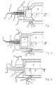
- FIGS. 1 and 2 are a burner and the adjoining part of the combustion chamber a Claus system, the burner shown in FIGS. 1 and 2 additionally has a combustor.
- Fig. 1 shows the burner (1), which with a 3-fold concentric tube (2) an inner pilot tube (3) via the middle tube (4) and a heating gas outer tube (5) the Claus / SWS gas are supplied. Air passes through line (6) passed into the burner (1). The combustion takes place in the combustor (7) and there subsequent combustion chamber (8).
- a nozzle (9) Oxygen introduced into the combustion chamber at high speed.
- the lance for introducing the oxygen (10) in their front area consists of a double-concentric tube, with the inner tube (11) of oxygen and a protective gas via the outer tube (12) is initiated to cool the nozzle (9).
- the angle “ ⁇ ” here denotes the Angle of inclination of the oxygen lance in relation to the flow direction (R).
- the angle "According to the invention, ⁇ lies in the range of 45 ° ( ⁇ ) and 90 ° ( ⁇ '). Connbustor (7) and Combustion chamber (8) are made in one piece here.
- Fig. 2 shows a similar embodiment as Fig. 1, wherein combustor (7) and combustion chamber (8) are separated from each other.
- the burner (1) has a triple concentric tube (2) with an inner tube (3) for pilot gas, a middle tube (4) for heating gas and an outer one Pipe (5) for Claus / SWS gas. Air is supplied via line (6).
- a combustor (7) is arranged in front of the combustion chamber (8).
- Oxygen and a protective gas are supplied via a double-concentric tube, the oxygen in the inner tube (11) and the protective gas in the outer tube (12).
- the oxygen lance is arranged in the device at an angle ⁇ to ⁇ '(45 ° to 90 °) with respect to the flow direction (R).
- the combustion chamber (8) connects directly to the burner (1) of the Claus plant on.
- the pilot gas is in via a separate pipe (13) initiated the burner.
Abstract
Description
Die Erfindung betrifft ein Verfahren zur Umwandlung von Schwefelwasserstoff (H2S) in elementaren Schwefel (S).The invention relates to a process for converting hydrogen sulfide (H 2 S) into elemental sulfur (S).
Schwefel wird bei vielen chemischen Verfahren entweder in elementarer Form oder in Form von Schwefelsäure benötigt. Aber Schwefel ist hochgiftig in Form von Schwefeldioxid (SO2) oder als Schwefelwasserstoff. Daher gibt es maximal zulässige Emissionsgrenzwerte für diese Schwefelverbindungen, die weltweit verschärft werden.In many chemical processes, sulfur is required either in elementary form or in the form of sulfuric acid. But sulfur is highly toxic in the form of sulfur dioxide (SO 2 ) or as hydrogen sulfide. There are therefore maximum permissible emission limit values for these sulfur compounds, which are being tightened worldwide.
Fossile Brennstoffe, wie Erdgas, Kohle, Ölsand, Ölschiefer und Erdöl, enthalten organische und anorganische Schwefelverbindungen. Es ist erforderlich, diese Schwefelverbindungen zu entfernen oder in unschädliche Schwefelverbindungen umzuwandeln. Für die Entfernung der Schwefelverbindungen aus Brennstoffen und Verbrennungsprodukten existieren eine Vielzahl von physikalischen und chemischen Umwandlungsprozessen.Contain fossil fuels such as natural gas, coal, oil sands, oil shale and petroleum organic and inorganic sulfur compounds. It is necessary to do this To remove sulfur compounds or in harmless sulfur compounds convert. For the removal of sulfur compounds from fuels and Combustion products exist in a variety of physical and chemical Conversion processes.
Bei festen Brennstoffen werden die Schwefelverbindungen nach der Verbrennung im Kraftwerk als Schwefeldioxid durch eine Rauchgasentschwefelung mittels Kalkmilch absorbiert und in Calciumsulfit umgewandelt. Durch Oxidation mit im Abgas enthaltenem Restsauerstoff entsteht als Endprodukt Gips.In the case of solid fuels, the sulfur compounds are burned in the Power plant as sulfur dioxide through flue gas desulfurization using milk of lime absorbed and converted into calcium sulfite. Through oxidation in the exhaust gas Residual oxygen contained is the end product of gypsum.
Bei flüssigen Brennstoffen, wie zum Beispiel Dieselkraftstoff oder leichtes Heizöl, sind maximal zulässige Schwefelgehalte vorgeschrieben. Denn eine Entschwefelung der Rauchgase nach einer eventuellen Verbrennung, zum Beispiel in Motoren, ist nicht mehr zu realisieren. Die Entschwefelung dieser Brennstoffe wird in den Raffinerien durchgeführt. Die im Rohöl vorhandenen Schwefelverbindungen werden im Destillat wiedergefunden, wobei die Schwerölfraktion die höchsten Schwefelkonzentrationen aufweist. With liquid fuels, such as diesel fuel or light heating oil, maximum permissible sulfur levels are prescribed. Because desulfurization the smoke gases after a possible combustion, for example in engines no longer realizable. The desulfurization of these fuels is carried out in the Refineries carried out. The sulfur compounds present in the crude oil are found in the distillate, the heavy oil fraction being the highest Has sulfur concentrations.
Die Entschwefelung erfolgt mit Hilfe von gasförmigem Wasserstoff (H2). Die organischen Schwefelverbindungen werden dabei in Schwefelwasserstoff umgewandelt. Der Schwefelwasserstoff, der im Gasgemisch mit Wasserstoff und anderen Kohlenwasserstoffen vorliegt, wird in Aminwäschern als Claus- oder Schwefelwasserstoffgas mit Konzentrationen von bis zu 90 Vol.% Schwefelwasserstoff ausgewaschen. Schwefelwasserstoff entsteht auch in den Sauerwasserstripperkolonnen. Hier liegt Schwefelwasserstoff als wässriges Kondensat vor und wird als Sauerwasserstrippergas (SWS-Gas) mit bis zu 50 Vol.% Schwefelwasserstoff ausgestrippt. Zusätzlich können bis zu 50 Vol.% Ammoniak (NH3) enthalten sein, das durch Zersetzung organischer Stickstoffverbindungen entsteht.Desulphurization takes place with the help of gaseous hydrogen (H 2 ). The organic sulfur compounds are converted into hydrogen sulfide. The hydrogen sulfide, which is present in the gas mixture with hydrogen and other hydrocarbons, is washed out in amine scrubbers as Claus or hydrogen sulfide gas with concentrations of up to 90% by volume of hydrogen sulfide. Hydrogen sulfide is also produced in the acid water stripper columns. Here, hydrogen sulfide is present as an aqueous condensate and is stripped out as an acid water stripping gas (SWS gas) with up to 50 vol.% Hydrogen sulfide. In addition, up to 50% by volume of ammonia (NH 3 ) can be contained, which is formed by the decomposition of organic nitrogen compounds.
Auch bei der Verbrennung von Kohle oder Schweröl in Kraftwerken, bei der der Brennstoff zuvor unter Sauerstoffmangel vergast wird, entsteht ein schwefelwasserstoffhaltiges Synthesegas, welches vor der Verbrennung gereinigt wird.Also when burning coal or heavy oil in power plants, where the If fuel is gasified beforehand with a lack of oxygen, a Syngas containing hydrogen sulfide, which is cleaned before combustion becomes.
Schwefelwasserstoff kommt außerdem in unterschiedlichen Konzentrationen im Erdölbegleitgas und im Erdgas mit einem Anteil von bis zu 30 Vol.% und im Abgas von Kläranlagen mit einem Anteil von bis zu 5 Vol.% Schwefelwasserstoff vor.Hydrogen sulfide also comes in different concentrations in the Associated petroleum gas and in natural gas with a share of up to 30 vol.% And in the exhaust gas of sewage treatment plants with a share of up to 5 vol.% hydrogen sulfide.
Die industrielle Verwertung von Schwefelwasserstoff ist begrenzt. Daher wird er zunächst in elementaren Schwefel und anschließend in speziellen Anlagen in Schwefelsäure umgewandelt. Elementarer Schwefel wird in der Gummiindustrie benötigt. Schwefelsäure wird in der chemischen Industrie eingesetzt.The industrial use of hydrogen sulfide is limited. Therefore he will first in elemental sulfur and then in special plants in Sulfuric acid converted. Elemental sulfur is used in the rubber industry needed. Sulfuric acid is used in the chemical industry.
Eine direkte Umwandlung von Schwefelwasserstoff in elementaren Schwefel ist durch eine thermische Spaltung von Schwefelwasserstoff, eine nasse Oxidation von Schwefelwasserstoff in einer flüssigen (wässrigen) Phase und eine trockene Oxidation von Schwefelwasserstoff in der Dampfphase möglich. There is a direct conversion of hydrogen sulfide into elemental sulfur by thermal cracking of hydrogen sulfide, wet oxidation of Hydrogen sulfide in a liquid (aqueous) phase and a dry one Oxidation of hydrogen sulfide possible in the vapor phase.
Das mit weltweit über 2000 Anlagen am häufigsten genutzt direkte Umwandlungsverfahren ist das bereits 1883 entwickelte Claus-Verfahren. Dieses Verfahren beruht auf einem trockenen Oxidationsprozeß. Eine Vielzahl von Prozeßvarianten sind entstanden. Alle Prozeßvarianten beruhen auf denselben chemischen Grundreaktionen sowie auf die Verwendung eines thermischen und eines katalytische Reaktors.The most used direct with over 2000 systems worldwide The conversion process is the Claus process, which was developed in 1883. This The process is based on a dry oxidation process. A variety of Process variants have emerged. All process variants are based on the same basic chemical reactions and the use of a thermal and of a catalytic reactor.
Der thermische Reaktor besteht aus einer Brennkammer mit einem Brenner, einem Abhitzekessel und einem ersten Schwefelkondensator. Der katalytische Reaktor ist zwei- oder dreistufig ausgeführt. Die Stufen weisen jeweils einen Erhitzer, ein Katalysatorbett und einen Schwefelkondensator auf.The thermal reactor consists of a combustion chamber with one burner, one Waste heat boiler and a first sulfur condenser. The catalytic reactor is executed in two or three stages. The steps each have a heater Catalyst bed and a sulfur condenser.
In der Brennkammer und den katalytischen Reaktoren laufen fologende chemische
Grundreaktionen ab:

Die übrigen, prozeßbedingt vorhandenen Begleitgase, wie zum Beispiel Wasserstoff, Methan, höhere Kohlenwasserstoffe, Ammoniak, Wasserdampf, Kohlendioxid, reagieren entsprechend ihren Konzentrationen in einer Vielzahl von Nebenreaktionen.The other associated process gases, such as hydrogen, Methane, higher hydrocarbons, ammonia, water vapor, carbon dioxide, react according to their concentrations in a variety of Side reactions.
Die eigentliche Clausreaktion zwischen Schwefeldioxid und Schwefelwasserstoff, bei
der elementarer Schwefel und Wasserdampf gebildet wird, ist Reaktion 2. Diese läuft
im Katalysatorbett ab. The actual Claus reaction between sulfur dioxide and hydrogen sulfide, at
the elemental sulfur and water vapor is formed,
Elementarer Schwefel wird darüber hinaus direkt durch die thermische Spaltung von
Schwefelwasserstoff in Schwefel und Wasser in der Brennkammer erzeugt:
Diese Reaktion ist stark endotherm.This reaction is very endothermic.
Verfahrenstechnisch wird ein Drittel der Schwefelwasserstoffmenge, meist ein Gemisch aus Claus- und Sauerwasserstrippergas, durch den Brenner mittels Verbrennungsluft unterstöchiometrisch zu einem Drittel Schwefeldioxid verbrannt. Der verbleibende Schwefelwasserstoff spaltet sich thermisch im Temperaturbereich zwischen 900°C bis 1300°C in der Brennkammer in Schwefel und Wasserstoff auf und wird katalytisch bei Temperaturen zwischen 180°C und 400°C in den katalytischen Reaktoren mit dem unverbrannten Schwefelwasserstoff zu elementaren Schwefel und Wasser umgesetzt. Die Umsetzung zu Schwefel ist optimal, wenn das Schwefelwasserstoff/Schwefeldioxid-Verhältnis zwei zu eins beträgt. Das optimale Verhältnis wird jedoch in der Praxis nur näherungsweise erreicht.In terms of process engineering, one third of the amount of hydrogen sulfide is usually one Mixture of Claus and acid water stripping gas, by means of the burner Combustion air is substoichiometrically burned to a third of sulfur dioxide. The remaining hydrogen sulfide splits thermally in the temperature range between 900 ° C and 1300 ° C in the combustion chamber in sulfur and hydrogen and becomes catalytically at temperatures between 180 ° C and 400 ° C in the elementary catalytic reactors with the unburned hydrogen sulfide Sulfur and water implemented. The conversion to sulfur is optimal if that Hydrogen sulfide / sulfur dioxide ratio is two to one. The optimal In practice, however, the ratio is only approximated.
Der in der Brennkammer gebildete elementare Schwefel wird nach Abkühlung des Prozeßgases nach dem Abhitzekessel und im ersten Schwefelkondensator bereits flüssig abgeschieden. In den nachgeschalteten katalytischen Reaktoren wird das abgekühlte Prozeßgas vor Eintritt in die Katalysatoren durch die vorgeschalteten Erhitzer mittels Hochdruckdampf oder Wärmeträgeröl auf die notwendige Reaktionstemperatur erhitzt. Der durch die Clausreaktion gebildete Schwefel wird ebenfalls in den Schwefelkondensatoren flüssig abgeschieden.The elemental sulfur formed in the combustion chamber is after cooling the Process gas after the waste heat boiler and in the first sulfur condenser separated liquid. In the downstream catalytic reactors, this becomes cooled process gas before entering the catalysts through the upstream Use high pressure steam or heat transfer oil to heat the necessary Reaction temperature heated. The sulfur formed by the Claus reaction becomes also separated in liquid form in the sulfur condensers.
Aufgrund der unterschiedlichen Schwefelwasserstoffkonzentration im Einsatzgas gibt es bei den konventionellen Claus-Prozessen zwei Hauptvarianten: den Hauptstrom-Betrieb für Schwefelwasserstoffkonzentrationen größer 50 Vol.% und den Nebenstrom-Betrieb für Schwefelwasserstoffkonzentrationen zwischen 30 Vol.% und 50 Vol.%. Due to the different hydrogen sulfide concentration in the feed gas There are two main variants of conventional Claus processes: the main current operation for hydrogen sulfide concentrations greater than 50% by volume and Sideline operation for hydrogen sulfide concentrations between 30 vol.% And 50 vol.%.
Beim Hauptstrom-Betrieb wird die gesamte Schwefelwasserstoffmenge mit der Verbrennuncasluft in der Brennkammer teilverbrannt. Durch die thermische Spaltung des Schwefelwasserstoffs in der Brennkammer wird bereits ein großer Schwefelanteil im ersten Schwefelkondensator nach dem Abhitzekessel abgeschieden. Für schwefelwasserstoffreiches Gas beträgt der Schwefelumsetzungsgrad bei einem dreistufigen Claus-Prozeß 96 bis 97 %.In the main stream operation, the total amount of hydrogen sulfide with the Combustion air partially burned in the combustion chamber. Through the thermal cleavage of the hydrogen sulfide in the combustion chamber is already a large proportion of sulfur deposited in the first sulfur condenser after the waste heat boiler. For hydrogen sulfide-rich gas is the degree of sulfur conversion at one three-stage Claus process 96 to 97%.
Nachgeschaltete Tailgasbehandlungsanlagen, meist Claus-Prozesse mit thermischer Nachverbrennung, ermöglichen es anschließend, die von der Anlagenkapazität abhängigen gesetzlichen Grenzwerte einzuhalten.Downstream tail gas treatment plants, mostly Claus processes with thermal Afterburning, then make it possible by the plant capacity dependent legal limits.
Bei Nebenstrom-Betrieb wird aufgrund des geringen Heizwertes des Schwefelwasserstoffgases der Gasstrom aufgeteilt. Mindestens ein Drittel des Schwefelwasserstoffgases wird mit der notwendigen Verbrennungsluft in der Brennkammer verbrannt und das entstandene schwefeldioxidreiche Reaktionsgas wird vor dem ersten Reaktor mit dem restlichen Schwefelwasserstoffgas vermischt. Bei diesem Prozeß wird in der Brennkammer kein elementarer Schwefel gebildet, da das Schwefelwasserstoff-Gas vollständig verbrannt wird.In the case of sidestream operation, the Hydrogen sulfide gas split the gas stream. At least a third of the Hydrogen sulfide gas is mixed with the necessary combustion air in the Combustion chamber burned and the resulting sulfur dioxide-rich reaction gas is mixed with the remaining hydrogen sulfide gas before the first reactor. In this process, no elemental sulfur is formed in the combustion chamber because the hydrogen sulfide gas is completely burned.
Bei Schwefelwasserstoffkonzentrationen kleiner 30 Vol.% ist auch der Nebenstrom-Betrieb aufgrund des niedrigen Heizwertes nicht mehr einsetzbar. Die Verbrennung wird dann instabil. Darüber hinaus erfordert der Nebenstrom-Betrieb in der Regel ein ammoniakfreies Einsatzgas. Sonst werden über den Bypass die Katalysatoren mit Ammoniak kontaminiert. Bei Anwesenheit von Ammoniak, beispielsweise bei Einsatz von Sauerwasserstrippergas, muß das Sauerwasserstrippergas, getrennt vom Clausgas in der Brennkammer verbrannt werden. Diese Qualitäten des Einsatzgases erfordern geänderte Varianten des Claus-Prozesses.In the case of hydrogen sulfide concentrations of less than 30% by volume, the bypass operation is also can no longer be used due to the low calorific value. The combustion then becomes unstable. In addition, the bypass operation usually requires one ammonia-free feed gas. Otherwise the catalytic converters are connected via the bypass Ammonia contaminated. In the presence of ammonia, for example when used of sour water stripping gas, the sour water stripping gas must be separated from the Clausgas are burned in the combustion chamber. These qualities of feed gas require modified variants of the Claus process.
Für eine produktionsbedingte Steigerung der Raffinationskapazität, einen Einsatz von preiswerteren aber schwefelreicheren Rohölqualitäten oder für reduzierte Schwefelkonzentrationsgrenzwerte im Endprodukt weisen die vorhandenen Claus-Anlagen oft ein zu geringe Schwefelkapazität auf. Der Begriff "Schwefelkapazität" bedeuted hier die pro Zeiteinheit erzeugte Menge an Schwefel.For a production-related increase in refining capacity, an insert from cheaper but sulfur-rich crude oil qualities or for reduced ones The existing Claus plants have sulfur concentration limits in the end product often too low a sulfur capacity. The term "sulfur capacity" means here the amount of sulfur produced per unit of time.
Neben dem eventuell notwendigen Neubau oder Umbau der Claus-Anlage, besteht auch die Möglichkeit, den apparativen Engpaß durch Verwendung von Sauerstoff zu umgehen. Bei diesen Verfahren wird die Verbrennungsluft teilweise oder vollständig durch Sauerstoff ersetzt. Durch den Einsatz von Sauerstoff wird die Verbrennungstemperatur erhöht und der Inertgasanteil wird reduziert oder eliminiert. Daß bedeutet, das spezifische Prozeßgasvolumen und damit der Anlagendruckverlust wird reduziert. Damit kann der Durchsatz von Sauerwassergas und Clausgas erhöht werden und schwefelwasserstoffarme Einsatzgase mit geringem Heizwert und hohem Ammoniak-Gehalt auch in einem Hauptstromreaktor verarbeitet werden. Die Anwendung von Sauerstoff in Clausanlagen ist heute Stand der Technik.In addition to the possibly necessary new construction or renovation of the Claus system, there is also the possibility of the equipment bottleneck by using oxygen bypass. In this process, the combustion air is partially or completely replaced by oxygen. By using oxygen, the combustion temperature is increased and the proportion of inert gas is reduced or eliminated. That means, the specific process gas volume and thus the system pressure loss reduced. This can increase the throughput of acid water gas and Claus gas and low hydrogen sulfide feed gases with low calorific value and high Ammonia content can also be processed in a mainstream reactor. The The use of oxygen in Claus plants is state of the art today.
Bei den heute eingesetzten Prozessen ist die Anreicherung der Verbrennungsluft mit Sauerstoff am einfachsten zu realisieren. Der Mehrdurchsatz an Schwefelwasserstoff ist proportional zur Menge an zugeführtem Sauerstoff. Die maximal mögliche Sauerstoffmenge wird durch die zulässigen Betriebstemperaturen des Brenners, des Abhitzekesseis und des ersten Reaktors begrenzt.In the processes used today, the enrichment of the combustion air is included The easiest way to realize oxygen. The increased throughput of hydrogen sulfide is proportional to the amount of oxygen supplied. The maximum possible The amount of oxygen is determined by the permissible operating temperatures of the burner, the Waste heat and the first reactor limited.
In Abhängigkeit vom vorhandenen Brenner beträgt die maximal zulässige Sauerstoffkonzentration 27 bis 28 Vol.%, wobei die zulässigen Betriebstemperaturen des Brenners, des Abhitzekessels und des ersten Reaktors limitierend sind. Der Umsetzungsgrad an Schwefel wird im Vergleich zum konventionellen Claus-Verfahren nicht erhöht.Depending on the existing burner, the maximum permitted Oxygen concentration 27 to 28 vol.%, The permissible operating temperatures of the burner, the waste heat boiler and the first reactor are limiting. The Degree of conversion of sulfur is compared to the conventional Claus process not increased.
Beim COPE-Prozeß wird die Verbrennungsluft mit Sauerstoff angereichert, wobei höhere Konzentrationen mit bis zu 100 Vol.% Sauerstoff realisiert werden können. Dazu wird ein spezieller Brenner und ein zusätzliches Kreislaufgebläse benötigt. Bei diesem Verfahren wird die durch die hohe Sauerstoffkonzentration bedingte Temperatursteigerung in der Brennkammer und im Abhitzekessel durch Rezirkulation von kaltem Prozeßgas kompensiert. Das Prozeßgas wird nach dem ersten Schwefelkondensator angesaugt und durch den Brenner in die Brennkammer zu einer Senkung der Temperatur eingeblasen. Aufgrund der höheren Prozeßgasmengen steigt der Druckverlust in der Brennkammer und im Abhitzekessel. In den nachgeschalteten katalytischen Reaktorstufen ist der Druckverlust aufgrund der reduzierten Prozeßgasmengen geringer.In the COPE process, the combustion air is enriched with oxygen, whereby higher concentrations can be achieved with up to 100 vol.% oxygen. A special burner and an additional circuit fan are required for this. at This process uses the high oxygen concentration Temperature increase in the combustion chamber and in the waste heat boiler through recirculation compensated by cold process gas. The process gas is after the first Sulfur condenser sucked in and through the burner into the combustion chamber a drop in temperature. Because of the higher Process gas quantities increase the pressure loss in the combustion chamber and in Waste heat boiler. In the downstream catalytic reactor stages Pressure loss is lower due to the reduced process gas quantities.
Der Lurgi-Sauerstoff-Clausbrenner ist ein Brenner, der mit Luft, mit Sauerstoff, oder mit Luft und Sauerstoff als Oxidationsmedium betrieben werden kann. Die maximal mögliche Sauerstoffkonzentration beträgt ca. 80 Vol.%. Das Clausgas und das ammoniakhaltige Sauerwasserstrippergas werden separat zugeführt. Das Sauerwasserstrippergas wird mit Luft in einer zentralen Brennermuffel zusammen mit dem Heizgas verbrannt. Das Clausgas wird mit Sauerstoff und Luft als Oxidationsmedium mit mehreren doppelkonzentrischen Einzelbrennern, die symmetrisch um die Brennermuffel angeordnet sind, verbrannt. Ein Einzelbrenner besteht aus einer zentralen Sauerstoffdüse, einer konzentrischen Clausgasdüse und einer doppelkonzentrischen Luftdüse. Durch dieser Anordnung entstehen einzelne Sauerstoff/Schwefelwasserstoff-Flammen, die von kälteren Luft/Schwefelwasserstoff-Flammen umhüllt werden. Dadurch wird die Temperatur in der Brennkammer kontrolliert. Eine Rezirkulation von kaltem Prozeßgas zur Temperaturabsenkung ist auch bei hohen Sauerstoffmengen nicht notwendig.The Lurgi-oxygen Claus burner is a burner that works with air, with oxygen, or can be operated with air and oxygen as the oxidation medium. The maximum possible oxygen concentration is approx. 80 vol.%. The Clausgas and that Sour water stripping gas containing ammonia is fed separately. The Acid water stripping gas is mixed with air in a central burner muffle the heating gas burned. The Claus gas is used with oxygen and air as the oxidation medium with several double concentric single burners, symmetrical around the Burner muffle are arranged, burned. A single burner consists of one central oxygen nozzle, a concentric Claus gas nozzle and one double concentric air nozzle. This arrangement creates individual ones Oxygen / hydrogen sulfide flames from colder air / hydrogen sulfide flames to be enveloped. This will change the temperature in the combustion chamber controlled. A recirculation of cold process gas to lower the temperature is not necessary even with high amounts of oxygen.
Beim SURE-Prozeß wird ebenfalls sauerstoffangereicherte Luft oder 100 Vol.% Sauerstoff als Oxidationsmedium verwendet.The SURE process also uses oxygen-enriched air or 100 vol.% Oxygen is used as the oxidation medium.
Beim SURE-Doppelverbrennungsprozeß wird die Verbrennung des Schwefelwasserstoffes mit zwei in Serie geschalteten, jeweils mit einem Abhitzekessel und einem Schwefelkondensator ausgerüsteten Brennkammern, durchgeführt. Das Schwefelwasserstofgas wird mit einer Teilmenge des Sauerstoffs in der ersten Brennkammer verbrannt, in einem Abhitzekessel abgekühlt, in die zweite Brennkammer durch einen Brenner überführt und die für die Clausreaktion benötigten Menge an Restsauerstoff zugegeben. Durch diese Aufteilung wird ebenfalls die Temperatur in den Brennkammern kontrolliert.The SURE double combustion process involves the combustion of the hydrogen sulfide with two series connected, each with a waste heat boiler and one Sulfur condenser equipped combustion chambers. The Hydrogen sulfide gas is used with a subset of the oxygen in the first Combustion chamber burned, cooled in a waste heat boiler, in the second Combustion chamber transferred through a burner and used for the Claus reaction required amount of residual oxygen added. This division will also controls the temperature in the combustion chambers.
Beim SURE-Seitenstrombrennerprozeß ist vor den vorhandenen Claus-Prozeß eine separate Brennkammer geschaltet. Das Schwefelwasserstoffgas wird auf beide Brennkammern aufgeteilt. In der ersten Brennkammer wird durch Verbrennung mit Sauerstoff ausschließlich Schwefeldioxid erzeugt. Zur Temperaturkontrolle wird nach dem Abhitzekessel ein Teilstrom des abgekühlten schwefeldioxidhaltigen Teilstroms mit dem restlichen Schwefelwasserstoffgas und Sauerstoff durch einen Brenner in die eigentliche Brennkammer eingeblasen, um das für die Clausreaktion notwendige Schwefelwasserstoff/Schwefeldioxid-Verhältnis einzustellen.In the SURE side stream burner process, there is one before the existing Claus process separate combustion chamber switched. The hydrogen sulfide gas is released on both Split combustion chambers. In the first combustion chamber is burned with Oxygen only produces sulfur dioxide. For temperature control is after a partial flow of the cooled sulfur dioxide-containing partial flow to the waste heat boiler with the remaining hydrogen sulfide gas and oxygen through a burner the actual combustion chamber is blown in to achieve what is necessary for the Claus reaction Adjust hydrogen sulfide / sulfur dioxide ratio.
Der Einsatz von bis zu 100 Vol. % Sauerstoff als Oxidationsmedium bietet das höchste Potential zur Leistungssteigerung von Claus-Anlagen. Dazu müssen aber nicht unerhebliche Investionskosten in die Anlagentechnik aufgewendet werden. Bei allen bekannten Sauerstoff-Claus-Verfahren müssen mindestens der Brenner und die Brennkammer ersetzt werden. Weitere Kosten entstehen, wenn zusätzlich ein Kreislaufgasgebläse oder eine zweite Brennkammer mit Abhitzekessel und Schwefelkondensator benötigt werden. Darüber hinaus ist der Betrieb eines Kreislaufgebläses durch mögliche Schwefelablagerungen nicht unproblematisch.The use of up to 100 vol.% Oxygen as an oxidation medium offers this highest potential for increasing the performance of Claus systems. But to do that not inconsiderable investment costs in the plant technology. at All known oxygen Claus processes must have at least the burner and the combustion chamber to be replaced. Additional costs arise if additional one Circulation gas blower or a second combustion chamber with a waste heat boiler and Sulfur condenser are needed. In addition, the operation of a Circulation blowers are not without problems due to possible sulfur deposits.
Das dann vorhandene hohe Potential an Durchsatzleistung kann jedoch meist nicht ausgeschöpft werden, da die nachgeschalteten Aggregate, wie zum Beispiel die katalytischen Reaktoren, einen Engpaß darstellen. Dagegen benötigt die Sauerstoffanreicherung die geringsten Investionskosten, bietet aber mit nur max. 28 Vol.% Sauerstoff in der Verbrennungsluft das geringste Potential zur Leistungssteigerung einer Claus-Anlage.However, the high potential of throughput that is then available usually cannot be exhausted because the downstream units, such as the catalytic reactors, a bottleneck. In contrast, the Oxygen enrichment has the lowest investment costs, but offers only a max. 28 vol.% Oxygen in the combustion air has the lowest potential for Performance increase of a Claus system.
Auch aus der Patentanmeldung WO-A-8 912 023 ist ein zweistufiges Verbrennungsverfahren von Schwefelwasserstoff bekannt, wobei sauerstoffreiches Gas zu einem Brenner geführt wird.From patent application WO-A-8 912 023 there is also a two-stage Combustion process of hydrogen sulfide known whereby oxygen-rich gas is led to a burner.
Der Erfindung liegt daher die Aufgabe zugrunde, die Nachteile des Standes der Technik zu überwinden und ein Verfahren vorzusehen, mit dem insbesondere die Durchsatzleistung und der Umsetungsgrad von Schwefelwasserstoff zu elementaren Schwefel verbessert wird. Das Verfahren soll darüber hinaus mit vergleichsweise geringem zusätzlichen Aufwand in bereits vorhandene Claus-Anlagen intergriert werden können.The invention is therefore based on the object, the disadvantages of the prior art To overcome technology and to provide a process with which in particular the throughput and the degree of implementation of Hydrogen sulfide is improved to elemental sulfur. The procedure is also said to have comparatively little additional Effort can be integrated into existing Claus systems.
Die Aufgabe wird mit einem Verfahren mit den Merkmalen gemäß des Anspruchs 1 gelöst. Bevorzugte Ausgestaltungen sind in den Unteransprüchen angegeben.The object is achieved with a method with the features according to claim 1 solved. preferred Refinements are specified in the subclaims.
Das erfindungsgemäße Verfahren hat den Vorteil, daß die Schwefelkapazität von Claus-Anlagen unter Verwendung von Sauerstoff oder eines sauerstoffreichen Gases erhöht wird, wobei nur geringe Investitionskosten nötig sind. Gleichzeitig sind aber wesentlich höhere Sauerstoffkonzentrationen oder Schwefelwasserstoffdurchsätze, im Vergleich zu einer konventionellen Sauerstoffanreicherung, möglich.The process according to the invention has the advantage that the sulfur capacity of Claus plants using oxygen or an oxygen-rich Gases is increased, with only low investment costs are necessary. Are at the same time but significantly higher oxygen concentrations or hydrogen sulfide throughputs, compared to conventional oxygenation.
Erfindungsgemäß wird der Sauerstoff nicht wie bisher nur als Oxidationsmedium
verwendet, sondern zusätzlich zur Steigerung der Mischungsenergie eingesetzt, um
die Vermischung zwischen Oxidationsmittel und Einsatzgas in der vorhandenen
Brennkammer zu verbessern. Durch die Steigerung der Mischungsenergie kann die
Verbrennungsdichte und damit der Durchsatz von Schwefelwasserstoff erhöht
werden. Denn in die vorhandene Brennkammer wird so eine zusätzliche
Nachverbrennungszone integriert, die durch hochturbulente selbstansaugende
Sauerstoffstrahlen erzeugt wird. Damit wird das aus dem Combustor oder dem
Brenner austretende, mit Luft teilreagierte bzw. vorgemischte Prozeßgas vollständig
nachverbrannt. Darüber hinaus laufen die in der Brennkammer stattfindenden
Reaktionen näher am thermodynamischen Gleichgewicht ab. Die Begriffe
"teilverbrennen" und "nachverbrennen" beziehen sich auf die stöchiometrische
Verbrennung.
Anstelle von technisch reinem Sauerstoff, der komprimiert per Rohrleitung angeliefert
wird oder verflüssigt aus vakuumisolierten Behältern mit hohem Druck entnommen
wird, kann auch Sauerstoff mit einer Reinheit von 80 Vol.% bis 100 Vol.%
Sauerstoffanteil verwendet werden. Dieser wird vorzugsweise durch
Molekularsiebadsorptionsanlagen, beispielsweise Vakuumwechseladsorptionsanlagen
(VSA) oder Vakuumdruckwechseladsorptionsanlagen (PVSA) direkt beim
Verbraucher hergestellt.According to the invention, the oxygen is not only used as an oxidation medium as before, but is also used to increase the mixing energy in order to improve the mixing between oxidizing agent and feed gas in the existing combustion chamber. By increasing the mixing energy, the combustion density and thus the throughput of hydrogen sulfide can be increased. This is because an additional post-combustion zone is integrated into the existing combustion chamber, which is generated by highly turbulent, self-priming oxygen jets. In this way, the process gas emerging from the combustor or the burner, partially reacted with air or premixed, is completely afterburned. In addition, the reactions taking place in the combustion chamber take place closer to the thermodynamic equilibrium. The terms "partially burn" and "afterburn" refer to stoichiometric combustion.
Instead of technically pure oxygen, which is delivered compressed by pipeline or liquefied from vacuum-insulated containers at high pressure, oxygen with a purity of 80 vol.% To 100 vol.% Oxygen content can also be used. This is preferably produced by molecular sieve adsorption plants, for example vacuum swing adsorption plants (VSA) or vacuum pressure swing adsorption plants (PVSA) directly at the consumer.
Der Zusatzsauerstoff wird erfindungsgemäß nicht wie bisher über den Brenner durch Anreicherung der Verbrennungsluft zudosiert, sondern vorzugsweise durch mindestens eine oder eine Vielzahl von Einzeldüsen mit hoher Geschwindigkeit eingeblasen. Diese sind, in Abhängigkeit von der vorhandenen Konstruktion der Brennkammer, in der Brennkammerwand im Übergangsbereich zum Combustor oder nach dem Brenner am Anfang der Brennkammer, symmetrisch verteilt eingebaut.According to the invention, the additional oxygen is not passed through the burner as before Enrichment of the combustion air metered in, but preferably by at least one or a plurality of individual nozzles at high speed blown. These are, depending on the existing construction of the Combustion chamber, in the combustion chamber wall in the transition area to the combustor or after the burner at the beginning of the combustion chamber, installed symmetrically distributed.
Das aus dem Combustor oder aus dem Brenner austretende, mit der Verbrennungsluft des Brenners unterstöchiometrisch verbrannte oder vorgemischte Prozeßgas wird infolge der intensiven Mischung mit dem Sauerstoff vollständig nachverbrannt und das für die Clausreaktion benötigte stöchiometrische Schwefelwasserstoff/Schwefeldioxid -Verhältnis von zwei zu eins eingestellt, wobei das Schwefelwasserstoff/Schwefeldioxid -Verhältnis vor der Tailgasbehandlungsanlage gemessen wird.The one coming out of the combustor or out of the burner with the Combustion air from the burner sub-stoichiometrically burned or premixed Process gas becomes complete due to the intensive mixing with the oxygen afterburned and the stoichiometric required for the Claus reaction Hydrogen sulfide / sulfur dioxide ratio set from two to one, whereby the hydrogen sulfide / sulfur dioxide ratio before Tail gas treatment plant is measured.
Für eine intensive Mischung liegt die Austrittsgeschwindigkeiten aus den Sauerstoffeinzeldüsen vorzugsweise in einem Bereich der Machzahl zwischen 0,4 und 2. Unter Machzahl (Ma) ist hier das Verhältnis der Düsenaustrittsgeschwindigkeit zur Schallgeschwindigkeit der Gase zu verstehen. Aufgrund der relativ hohen Austrittsgeschwindigkeit des Sauerstoffs entstehen hochturbulente Freistrahlen, die die umgebende Brennkammeratmosphäre ansaugen, sich vermischen und mit den brennbaren Bestandteilen reagieren. Der Schwefelwasserstoff wird dabei zu Schwefeldioxid verbrannt.For an intensive mix, the exit speeds are from the Individual oxygen nozzles preferably in a Mach number range between 0.4 and 2. Mach number (Ma) is the ratio of the nozzle outlet speed to understand the speed of sound of the gases. Because of the relatively high The exit velocity of the oxygen creates highly turbulent free jets suck in the surrounding combustion chamber atmosphere, mix and mix with the flammable components react. The hydrogen sulfide becomes too Burned sulfur dioxide.
Bei einer Austrittsgeschwindigkeit entsprechend einer Machzahl von eins, daß heißt
Schallgeschwindigkeit, stellt sich zum Beispiel aufgrund der intensiven Mischung das
stöchiometrische Schwefelwasserstoff/Schwefeldioxid -Verhältnis von zwei zu eins
ein. Das bedeutet, der in der Brennkammer vorhandene Sauerstoff wird vollständig
umgesetzt. Durch die vollständige Umsetzung des Sauerstoffs wird die Standzeit des
ersten katalytischen Reaktors verlängert. Denn bei Reaktortemperaturen von 380°C
bis 550°C reagiert der sonst in Claus-Anlagen vorhandene Überschußsauerstoff mit
dem vorhandenen Schwefeldioxid zu Schwefeltrioxid (SO3), das mit den
Katalysatorpellets aus Aluminiumoxid nach der folgenden Reaktionsgleichung
reagiert:
Es bildet sich Aluminiumsulfat, das die Katalysatoroberfläche belegt und damit den Katalysator inaktiviert.It forms aluminum sulfate, which covers the catalyst surface and thus the Catalyst inactivated.
Darüber hinaus werden bei Sauerstoffgeschwindigkeiten entsprechend einer Machzahl von eins, die Sauerstoffdüsen thermisch entlastet, da sich die Flammen der Schwefelwasserstoff/Schwefeldioxid-Freistrahldiffusionsflammen nicht an der Düse stabilisieren, sondern von der Düse abgehoben, frei in der Brennkammer brennen. Zudem werden die Flammenwurzeln so von den Sauerstoffdüsen weg in den Brennraum hinein verlagert. Der für eine Sauerstoffgeschwindigkeit entsprechend einer Machzahl von eins notwendige Sauerstoffabsolutdruck am Düsenaustritt sollte vorzusweise das 1,93-fache des in der Brennkammer herrschenden Druckes (PBRK) betragen.In addition, at oxygen velocities corresponding to one Mach number of one that thermally relieves oxygen nozzles because of the flames the hydrogen sulfide / sulfur dioxide free jet diffusion flames are not on the Stabilize the nozzle, but lift it off the nozzle, freely in the combustion chamber burn. In addition, the flame roots are removed from the oxygen nozzles relocated the combustion chamber. The one for an oxygen velocity according to a Mach number of one necessary oxygen absolute pressure on The nozzle outlet should preferably be 1.93 times that in the combustion chamber prevailing pressure (PBRK).
Der Neigungswinkel der Sauerstoffinjektionslanzen beträgt vorzugsweiswe 45° bis 90° zur Strömungsrichtung, wobei die Achsen der Sauerstoffstrahlen sich in der Mittelachse der Brennkammer schneiden. Die Sauerstoffinjektionslanzen sind mit den Düsen vorteilhaft bündig oder zurückgezogen in die Innenwand der Brennkammer eingebaut.The angle of inclination of the oxygen injection lances is preferably 45 ° to 90 ° to the direction of flow, the axes of the oxygen jets being in the Cut the central axis of the combustion chamber. The oxygen injection lances are included the nozzles advantageously flush or withdrawn into the inner wall of the Combustion chamber installed.
Bei Brenner, die Drallflammen erzeugen, daß bedeutet, die eine radiale Geschwindigkeits- und Konzentratonsverteilung der einzelnen Gaskomponenten in der Brennkammer aufweisen, werden die Sauerstoffinjektionslanzen vorzugsweise im Abstand von ca. 0,25 des Brennkammerdurchmessers, von der Mitte der Brennkammer gemessen, symmetrisch am Umfang verteilt, eingebaut. Dadurch wird eine entgegen dem Drall der Hauptflamme gerichtete Sauerstoffdrallströmung erzeugt.In the case of burners that produce swirl flames, that means a radial Speed and concentration distribution of the individual gas components in the combustion chamber, the oxygen injection lances are preferably in Distance of approx. 0.25 of the combustion chamber diameter from the center of the Combustion chamber measured, symmetrically distributed around the circumference, installed. This will an oxygen swirl flow directed against the swirl of the main flame generated.
Die Sauerstoffinjektionslanzen sind vorzugsweise konzentrisch, wobei die Sauerstoffdüse von einer Ringspaltdüse umhüllt wird. Durch die Ringspaltdüse wird vorteilhaft permanent ein Schutzgas mit einer Mindestaustrittsgeschwindigkeit entsprechend einer Machzahl von 0,2 in die Brennkammer eingeblasen, um die Sauerstoffdüse zu kühlen und vor eindiffundierendem Schwefel zu schützen.The oxygen injection lances are preferably concentric, with the Oxygen nozzle is enveloped by an annular gap nozzle. Through the annular gap nozzle advantageously a protective gas with a minimum exit speed blown into the combustion chamber according to a Mach number of 0.2 in order to obtain the To cool the oxygen nozzle and to protect it against the diffusion of sulfur.
Als Schutzgas wird vorzugsweise Luft, Stickstoff oder Kohlendioxid verwendet.Air, nitrogen or carbon dioxide is preferably used as the protective gas.
Versuche haben gezeigt, daß mit diesem Verfahren, in Abhängigkeit von der
Schwefelwasserstoffkonzentration, äquivalente Sauerstoffkonzentrationen (XO2) von
21 Vol.% bis 40 Vol.% Sauerstoff realisiert werden können. Die äquivalente
Sauerstoffkonzentration wird hier durch die Gleichung
Die Mengen an Claus- und Sauerwasserstrippergas werden entsprechend dem
Sauerstoffangebot erhöht.Experiments have shown that, depending on the hydrogen sulfide concentration, equivalent oxygen concentrations (XO 2 ) of 21% by volume to 40% by volume of oxygen can be achieved with this method. The equivalent oxygen concentration here is given by the equation
The amounts of Claus and acid water stripping gas are increased in accordance with the oxygen supply.
Die nachfolgenden Beispiele zeigen, daß aufgrund der hohen äquivalenten
Sauerstoffkonzentration und Verbrennungsdichte die Temperatur in der
Brennkammer steigt. Im Abhitzekessel wird aufgrund der höheren Abwärmemenge
mehr Dampf erzeugt (siehe Tabelle).
Bei einer Erhöhung der zulässigen Brennkammertemperatur von 1500°C kann die äquivalente Sauerstoffkonzentration auf mindestens 40 Vol.% gesteigert werden. Da Wärme und Stoff gleich schnell ausgetauscht werden, wird die Temperatur in der Brennkammer infolge der intensiven Vermischung auf höherem Niveau vergleichmäßigt und der Wärmeübergang auf die Brennkammerwand verbessert. Daß bedeutet, der über die Brennkammerwand an die Umgebung abgegebene Wärmeanteil ist größer. Der Abhitzekessel wird thermisch entlastet. Die Temperaturen am Brenner und im Combustor steigen nicht an.With an increase in the permissible combustion chamber temperature of 1500 ° C equivalent oxygen concentration can be increased to at least 40 vol.%. There Heat and material are exchanged quickly, the temperature in the Combustion chamber homogenized at a higher level due to intensive mixing and the heat transfer to the combustion chamber wall is improved. That means that released into the environment via the combustion chamber wall The proportion of heat is greater. The waste heat boiler is thermally relieved. The Temperatures at the burner and in the combustor do not rise.
Verfahrensbedingt steigen die Temperaturen durch den höheren Schwefelumsatz im katalytischen Reaktor an, wobei die zulässige Betriebstemperatur des Katalysators von bis zu 650°C ausgenutzt werden kann. Die hohen Verbrennungstemperaturen bei dem Einsatz von Sauerstoff wirken sich positiv auf die thermische Spaltung und vollständige Verbrennung von höheren Kohlenwasserstoffen und von Ammoniak aus, wobei insbesondere für eine vollständige Ammoniak-Spaltung und Verbrennung eine Mindesttemperatur von 1350°C eingehalten werden sollte. Bedingt durch den fehlenden Stickstoffballast kann bei einer äquivalenten Sauerstoffkonzentration von 40 Vol.% die Konzentration an Schwefelwasserstoffgas im eingesetzten Gasgemisch auf 20 Vol.% Schwefelwasserstoff abgesenkt werden.Due to the process, the temperatures rise due to the higher sulfur conversion in the catalytic reactor, the permissible operating temperature of the catalyst of up to 650 ° C can be used. The high combustion temperatures when using oxygen have a positive effect on the thermal cleavage and complete combustion of higher hydrocarbons and ammonia, a particularly for complete ammonia splitting and combustion Minimum temperature of 1350 ° C should be maintained. Due to the Missing nitrogen ballast can occur at an equivalent oxygen concentration of 40 vol.% The concentration of hydrogen sulfide gas in the gas mixture used can be reduced to 20% by volume of hydrogen sulfide.
Die Erfindung wird nun anhand von Abbildungen (Fig. 1 bis 3) näher erläutert.The invention will now be explained in more detail with the aid of illustrations (FIGS. 1 to 3).
In Fig. 1 bis 3 sind ein Brenner und der daran anschließende Teil der Brennkammer einer Claus-Anlage dargestellt, wobei der in Fig. 1 und Fig. 2 dargestellte Brenner zusätzlich einen Combustor aufweist.1 to 3 are a burner and the adjoining part of the combustion chamber a Claus system, the burner shown in FIGS. 1 and 2 additionally has a combustor.
Fig. 1 zeigt den Brenner (1), welchem über ein 3-fach konzentrisches Rohr (2) mit einem inneren Pilotrohr (3) über das mittlere Rohr (4) ein Heizgas und über das äußere Rohr (5) das Claus-/SWS-Gas zugeführt werden. Über Leitung (6) wird Luft in den Brenner (1) geleitet. Die Verbrennung erfolgt im Combustor (7) und daran anschließender Brennkammer (8). Gemäß der Erfindung wird über eine Düse (9) Sauerstoff in die Brennkammer mit hoher Geschwindigkeit eingebracht. Ferner ist hier dargestellt, daß die Lanze zum Einbringen des Sauerstoffs (10) in deren vorderen Bereich aus einem doppelkonzentrischem Rohr besteht, wobei über das innere Rohr (11) der Sauerstoff und über das äußere Rohr (12) ein Schutzgas eingeleitet wird, um die Düse (9) zu kühlen. Der Winkel "β " bezeichnet hier den Neigungswinkel der Sauerstofflanze in Bezug zur Strömungsrichtung (R). Der Winkel "β liegt erfindungsgemäß im Bereich von 45° (β) und 90° (β'). Connbustor (7) und Brennkammer (8) sind hier einteilig ausgeführt.Fig. 1 shows the burner (1), which with a 3-fold concentric tube (2) an inner pilot tube (3) via the middle tube (4) and a heating gas outer tube (5) the Claus / SWS gas are supplied. Air passes through line (6) passed into the burner (1). The combustion takes place in the combustor (7) and there subsequent combustion chamber (8). According to the invention, a nozzle (9) Oxygen introduced into the combustion chamber at high speed. Furthermore is shown here that the lance for introducing the oxygen (10) in their front area consists of a double-concentric tube, with the inner tube (11) of oxygen and a protective gas via the outer tube (12) is initiated to cool the nozzle (9). The angle "β" here denotes the Angle of inclination of the oxygen lance in relation to the flow direction (R). The angle "According to the invention, β lies in the range of 45 ° (β) and 90 ° (β '). Connbustor (7) and Combustion chamber (8) are made in one piece here.
Fig. 2 zeigt eine ähnliche Ausführungsform wie Fig. 1, wobei Combustor (7) und
Brennkammer (8) voneinander getrennt sind. Der Brenner (1) weist ein 3-fach
konzentrisches Rohr (2) mit einem inneren Rohr (3) für Pilotgas, einem mittleren
Rohr (4) für Heizgas und einem äußeren
Rohr (5) für Claus-/SWS-Gas auf. Luft wird über Leitung (6) zugeführt. Vor der
Brennkammer (8) ist ein Combustor (7) angeordnet. Sauerstoff und ein Schutzgas
werden über ein doppelkonzentrisches Rohr zugeführt, wobei der Sauerstoff im
inneren Rohr (11) und das Schutzgas im äußeren Rohr (12) geführt werden. Die
Sauerstofflanze ist um den Winkel β bis β' (45° bis 90°) gegenüber der
Strömungsrichtung ( R ) geneigt in der Vorrichtung angeordnet.Fig. 2 shows a similar embodiment as Fig. 1, wherein combustor (7) and combustion chamber (8) are separated from each other. The burner (1) has a triple concentric tube (2) with an inner tube (3) for pilot gas, a middle tube (4) for heating gas and an outer one
Pipe (5) for Claus / SWS gas. Air is supplied via line (6). A combustor (7) is arranged in front of the combustion chamber (8). Oxygen and a protective gas are supplied via a double-concentric tube, the oxygen in the inner tube (11) and the protective gas in the outer tube (12). The oxygen lance is arranged in the device at an angle β to β '(45 ° to 90 °) with respect to the flow direction (R).
In Fig. 3 schließt die Brennkammer (8) direkt an den Brenner (1) der Claus-Anlage an. Bei dieser Ausführungsform wird das Pilotgas über ein getrenntes Rohr (13) in den Brenner eingeleitet.In Fig. 3, the combustion chamber (8) connects directly to the burner (1) of the Claus plant on. In this embodiment, the pilot gas is in via a separate pipe (13) initiated the burner.
Claims (14)
- Process for producing elemental sulphur by combustion of hydrogen sulphide or a hydrogen-sulphide-containing gas, in particular a Claus process, in which the hydrogen sulphide or the hydrogen-sulphide-containing gas is, via a first device, partially combusted in a burner in a combustion chamber with addition of air as oxidation medium, oxygen or oxygen-containing gas being fed to the combustion chamber by at least one second additional device of the combustion chamber, by which means the hydrogen sulphide or the hydrogen-sulphide-containing gas is subjected to afterburning and is then fed to a waste-heat boiler and thereafter to one or more reactors, the oxygen-containing gas containing 80% by volume to 100% by volume of oxygen.
- Process according to Claim 1, in which the oxygen or the oxygen-containing gas is blown in by one or a multiplicity of individual nozzles.
- Process according to Claim 1 or 2, in which the intake velocity of the oxygen or the oxygen-containing gas into the combustion chamber is in the range of a Mach number between 0.4 and 2, as a result of which the mixing between the oxygen, the combustion air and the hydrogen-sulphide-containing process gas is increased on account of high turbulence.
- Process according to one of Claims 1 to 3, in which the oxygen or the oxygen-containing gas enters into the combustion chamber at an angle of 45° to 90° measured in the direction of flow.
- Process according to one of Claims 1 to 4, in which, in the case of a process having swirl of the main flame in the combustion chamber, a swirl flow of the oxygen or oxygen-containing gas is produced which is directed against the swirl of the main flame.
- Process according to one of Claims 1 to 5, in which the entry point of the oxygen or the oxygen-containing gas into the combustion chamber is cooled and is protected against sulphur diffusing in.
- Process according to Claim 6, in which, for cooling, in addition, a protecting gas is fed to the combustion chamber in the region of the point of entry of the oxygen or the oxygen-containing gas into the combustion chamber.
- Process according to Claim 7, in which air, nitrogen or carbon dioxide is used as protecting gas.
- Process according to Claim 7 or 8, in which the intake velocity of the protective gas into the combustion chamber is at least Mach number 0.2, as a result of which the turbulent mixture between the oxygen, the combustion air and the hydrogen-sulphide-containing process gas is additionally increased.
- Process according to one of Claims 1 to 9, in which the rate of oxygen fed is controlled in accordance with the stoichiometry of the Claus reaction in such a manner that the oxygen and the combustion air react completely with the hydrogen sulphide and the other combustible gases so that no excess oxygen is present downstream of the combustion chamber.
- Process according to one of Claims 1 to 10, in which the rate of oxygen fed is controlled in accordance with the stoichiometry of the Claus reaction in such a manner that the hydrogen sulphide/sulphur dioxide ratio corresponds to the theoretical value 2.
- Process according to one of Claims 1 to 11, in which the rate of oxygen fed is controlled in accordance with the stoichiometry of the Clause reaction in such a manner that the maximum temperatures in the burner/combustor are 250°C/1200°C and the maximum temperature in the combustion chamber is 1500°C, so that the heat transfer to the combustion chamber wall is improved and the maximum temperature in the waste-heat boiler is 670°C.
- Process according to one of Claims 1 to 12, in which the equivalent oxygen concentration is between 21 and 40% by volume.
- Process according to one of Claims 1 to 13, in which the concentration of the hydrogen sulphide in the feed gas is at least 20% by volume.
Applications Claiming Priority (3)
| Application Number | Priority Date | Filing Date | Title |
|---|---|---|---|
| DE19718261A DE19718261A1 (en) | 1997-04-30 | 1997-04-30 | Method and device for converting hydrogen sulfide into elemental sulfur |
| DE19718261 | 1997-04-30 | ||
| PCT/EP1998/002297 WO1998049098A1 (en) | 1997-04-30 | 1998-04-17 | Method and device for converting hydrogen sulfide into elemental sulfur |
Publications (2)
| Publication Number | Publication Date |
|---|---|
| EP0977708A1 EP0977708A1 (en) | 2000-02-09 |
| EP0977708B1 true EP0977708B1 (en) | 2004-10-20 |
Family
ID=7828220
Family Applications (1)
| Application Number | Title | Priority Date | Filing Date |
|---|---|---|---|
| EP98924145A Expired - Lifetime EP0977708B1 (en) | 1997-04-30 | 1998-04-17 | Method and device for converting hydrogen sulfide into elemental sulfur |
Country Status (9)
| Country | Link |
|---|---|
| US (1) | US6780392B2 (en) |
| EP (1) | EP0977708B1 (en) |
| AT (1) | ATE280128T1 (en) |
| DE (2) | DE19718261A1 (en) |
| ES (1) | ES2231986T3 (en) |
| HR (1) | HRP980160B1 (en) |
| PL (1) | PL191175B1 (en) |
| WO (1) | WO1998049098A1 (en) |
| ZA (1) | ZA983616B (en) |
Families Citing this family (16)
| Publication number | Priority date | Publication date | Assignee | Title |
|---|---|---|---|---|
| DE19951909C2 (en) * | 1999-10-28 | 2002-01-24 | Ruhr Oel Gmbh | Process for the combustion of acid water stripping gas |
| GB9929330D0 (en) * | 1999-12-10 | 2000-02-02 | Boc Group Plc | Sulphur recovery |
| JP3924150B2 (en) * | 2001-10-26 | 2007-06-06 | 三菱重工業株式会社 | Gas combustion treatment method and apparatus |
| US7108842B2 (en) * | 2004-01-15 | 2006-09-19 | Conocophillips Company | Process for the catalytic partial oxidation of H2S using staged addition of oxygen |
| US7416571B2 (en) * | 2005-03-09 | 2008-08-26 | Conocophillips Company | Compact mixer for the mixing of gaseous hydrocarbon and gaseous oxidants |
| US7226572B1 (en) | 2006-03-03 | 2007-06-05 | Conocophillips Company | Compact sulfur recovery plant and process |
| US7501111B2 (en) | 2006-08-25 | 2009-03-10 | Conoco Phillips Company | Increased capacity sulfur recovery plant and process for recovering elemental sulfur |
| CN102369236A (en) * | 2009-03-17 | 2012-03-07 | T.D.E.回收技术有限公司 | Environmentally clean process for utilizing pyrolysis products |
| DE102009018911A1 (en) * | 2009-04-28 | 2011-01-20 | Lurgi Gmbh | Process for producing process gas for the Claus process |
| US9708196B2 (en) | 2013-02-22 | 2017-07-18 | Anschutz Exploration Corporation | Method and system for removing hydrogen sulfide from sour oil and sour water |
| CA2843041C (en) | 2013-02-22 | 2017-06-13 | Anschutz Exploration Corporation | Method and system for removing hydrogen sulfide from sour oil and sour water |
| US11440815B2 (en) | 2013-02-22 | 2022-09-13 | Anschutz Exploration Corporation | Method and system for removing hydrogen sulfide from sour oil and sour water |
| US9364773B2 (en) | 2013-02-22 | 2016-06-14 | Anschutz Exploration Corporation | Method and system for removing hydrogen sulfide from sour oil and sour water |
| RU2530096C1 (en) * | 2013-02-27 | 2014-10-10 | Открытое акционерное общество "Гипрогазоочистка" | Method of producing sulphur from hydrogen sulphide-containing gas by claus method and catalytic reactor therefor |
| RU2711363C1 (en) * | 2015-06-17 | 2020-01-16 | Чайна Петролеум Энд Кемикал Корпорейшн | Method of treating spent acid after alkylation and device for implementing said method |
| WO2019105956A1 (en) * | 2017-11-28 | 2019-06-06 | Haldor Topsøe A/S | Method for production of sulfur and sulfuric acid |
Family Cites Families (9)
| Publication number | Priority date | Publication date | Assignee | Title |
|---|---|---|---|---|
| FR2424875A1 (en) * | 1978-05-02 | 1979-11-30 | Elf Aquitaine | PROCESS FOR THE PRODUCTION OF SULFUR FROM TWO ACIDIC GASES CONTAINING H2S AND OF WHICH ONE SINGLE CONTAINS NH3 |
| FR2509192A1 (en) * | 1981-07-10 | 1983-01-14 | Krupp Koppers Gmbh | METHOD FOR REMOVING SIMULTANEOUS ELEMENTARY SULFUR FROM WASTE WATER FORMING DURING DESULFURIZATION OF COKERIE GAS WITH A WASHING SOLUTION CONTAINING OXYGEN VECTORS |
| GB2107450B (en) * | 1981-10-14 | 1984-11-14 | Shell Int Research | Process for combusting hydrogen sulphide-containing gases and burner for use in such a process |
| US4888162A (en) * | 1984-07-03 | 1989-12-19 | Air Products And Chemicals, Inc. | Temperature moderation with water of an oxygen enriched claus sulfur plant |
| US4632818A (en) * | 1984-10-03 | 1986-12-30 | Air Products And Chemicals, Inc. | Production of sulfur from an oxygen enriched claus system |
| WO1989012023A1 (en) * | 1988-06-08 | 1989-12-14 | American Combustion, Inc. | Method and apparatus for recovering sulfer from gases containing hydrogen sulfide |
| US5028409A (en) * | 1988-07-26 | 1991-07-02 | American Combustion, Inc. | Method and apparatus for recovering sulfur from gases containing hydrogen sulfide |
| GB9314212D0 (en) * | 1993-07-09 | 1993-08-18 | Boc Group Plc | A gas combuster/reactor |
| GB9419133D0 (en) * | 1994-09-19 | 1994-11-09 | Wickham Michael | A method of forming sulphur |
-
1997
- 1997-04-30 DE DE19718261A patent/DE19718261A1/en not_active Ceased
-
1998
- 1998-03-26 HR HR980160A patent/HRP980160B1/en not_active IP Right Cessation
- 1998-04-17 PL PL336474A patent/PL191175B1/en unknown
- 1998-04-17 AT AT98924145T patent/ATE280128T1/en active
- 1998-04-17 ES ES98924145T patent/ES2231986T3/en not_active Expired - Lifetime
- 1998-04-17 US US09/403,081 patent/US6780392B2/en not_active Expired - Lifetime
- 1998-04-17 WO PCT/EP1998/002297 patent/WO1998049098A1/en active IP Right Grant
- 1998-04-17 EP EP98924145A patent/EP0977708B1/en not_active Expired - Lifetime
- 1998-04-17 DE DE59812152T patent/DE59812152D1/en not_active Expired - Lifetime
- 1998-04-29 ZA ZA983616A patent/ZA983616B/en unknown
Also Published As
| Publication number | Publication date |
|---|---|
| HRP980160A2 (en) | 1999-02-28 |
| HRP980160B1 (en) | 2005-04-30 |
| ATE280128T1 (en) | 2004-11-15 |
| ZA983616B (en) | 1998-11-02 |
| PL336474A1 (en) | 2000-06-19 |
| WO1998049098A1 (en) | 1998-11-05 |
| DE59812152D1 (en) | 2004-11-25 |
| DE19718261A1 (en) | 1998-11-05 |
| EP0977708A1 (en) | 2000-02-09 |
| PL191175B1 (en) | 2006-03-31 |
| US6780392B2 (en) | 2004-08-24 |
| US20020031468A1 (en) | 2002-03-14 |
| ES2231986T3 (en) | 2005-05-16 |
Similar Documents
| Publication | Publication Date | Title |
|---|---|---|
| EP0977708B1 (en) | Method and device for converting hydrogen sulfide into elemental sulfur | |
| KR100608432B1 (en) | Partial combustion of hydrogen sulphide | |
| DE1926629C3 (en) | Process for removing ammonia separated from coke oven gases and their condensates | |
| EP2507167B1 (en) | Method for making sulphuric acid | |
| US7695701B2 (en) | Process for treating acid gas in staged furnaces with inter-stage heat recovery | |
| EP0160332B1 (en) | Process for eliminating hydrogen sulfide from exhaust gases and for producing sulfur by the claus- process | |
| EP0132584B1 (en) | Method and installation for reducing the emission of noxious matter in the flue gases of combustion plants | |
| DE2613343A1 (en) | PROCESS FOR THE RECOVERY OF SULFUR FROM GASES WITH SO DEEP TWO CONTENT | |
| EP3283834A1 (en) | Plant for production of cement with reduced emission of pollutant gases | |
| DE10045322A1 (en) | Atomizing burner for the thermal splitting of sulfur-containing residues | |
| CA1197665A (en) | Process and apparatus for the combustion of ammonia- containing waste gases | |
| DE3636024C2 (en) | ||
| DE60012291T2 (en) | Process for the recovery of sulfur compounds | |
| EP0496101A1 (en) | Process for the thermal treatment of ammonium sulfate containing wastes especially ammonium sulfate containing waste-waters | |
| DE19951909C2 (en) | Process for the combustion of acid water stripping gas | |
| DE19853162C2 (en) | Process for burning a nitrogenous fuel | |
| DE3331545A1 (en) | Process and plant for reducing the pollutant emission in flue gases of furnaces | |
| WO2020244802A1 (en) | Process and apparatus for obtaining sulfur | |
| DE3618514A1 (en) | Method for operating a catalytic nitrogen oxide reduction stage | |
| DE4419193A1 (en) | Process for burning and afterburning gases to reduce nitrogen oxide emissions | |
| US20080286704A1 (en) | Method of burning a nitrogen-containing fuel | |
| DE2940321A1 (en) | Gaseous and/or liq. waste continuous thermal conversion - divides all waste streams into equal number of mixed partial streams | |
| DE2224233B2 (en) | METHOD FOR OPERATING A MIXED-LOADED SHAFT FURNACE FOR BURNING LIMESTONE AND DEVICE FOR CARRYING OUT THE METHOD |
Legal Events
| Date | Code | Title | Description |
|---|---|---|---|
| PUAI | Public reference made under article 153(3) epc to a published international application that has entered the european phase |
Free format text: ORIGINAL CODE: 0009012 |
|
| 17P | Request for examination filed |
Effective date: 19991130 |
|
| AK | Designated contracting states |
Kind code of ref document: A1 Designated state(s): AT BE CH CY DE ES FI FR GB GR IT LI NL SE |
|
| AX | Request for extension of the european patent |
Free format text: RO PAYMENT 19991130;SI PAYMENT 19991130 |
|
| 17Q | First examination report despatched |
Effective date: 20000828 |
|
| RAP1 | Party data changed (applicant data changed or rights of an application transferred) |
Owner name: MESSER GRIESHEIM GMBH |
|
| GRAP | Despatch of communication of intention to grant a patent |
Free format text: ORIGINAL CODE: EPIDOSNIGR1 |
|
| GRAS | Grant fee paid |
Free format text: ORIGINAL CODE: EPIDOSNIGR3 |
|
| GRAA | (expected) grant |
Free format text: ORIGINAL CODE: 0009210 |
|
| AK | Designated contracting states |
Kind code of ref document: B1 Designated state(s): AT BE CH CY DE ES FI FR GB GR IT LI NL SE |
|
| AX | Request for extension of the european patent |
Extension state: RO SI |
|
| REG | Reference to a national code |
Ref country code: GB Ref legal event code: FG4D Free format text: NOT ENGLISH |
|
| REG | Reference to a national code |
Ref country code: CH Ref legal event code: EP |
|
| REF | Corresponds to: |
Ref document number: 59812152 Country of ref document: DE Date of ref document: 20041125 Kind code of ref document: P |
|
| PG25 | Lapsed in a contracting state [announced via postgrant information from national office to epo] |
Ref country code: SE Free format text: LAPSE BECAUSE OF FAILURE TO SUBMIT A TRANSLATION OF THE DESCRIPTION OR TO PAY THE FEE WITHIN THE PRESCRIBED TIME-LIMIT Effective date: 20050120 Ref country code: GR Free format text: LAPSE BECAUSE OF FAILURE TO SUBMIT A TRANSLATION OF THE DESCRIPTION OR TO PAY THE FEE WITHIN THE PRESCRIBED TIME-LIMIT Effective date: 20050120 |
|
| RAP2 | Party data changed (patent owner data changed or rights of a patent transferred) |
Owner name: AIR LIQUIDE DEUTSCHLAND GMBH |
|
| RAP2 | Party data changed (patent owner data changed or rights of a patent transferred) |
Owner name: AIR LIQUIDE DEUTSCHLAND GMBH |
|
| GBT | Gb: translation of ep patent filed (gb section 77(6)(a)/1977) |
Effective date: 20050224 |
|
| PG25 | Lapsed in a contracting state [announced via postgrant information from national office to epo] |
Ref country code: CY Free format text: LAPSE BECAUSE OF FAILURE TO SUBMIT A TRANSLATION OF THE DESCRIPTION OR TO PAY THE FEE WITHIN THE PRESCRIBED TIME-LIMIT Effective date: 20050417 |
|
| NLT2 | Nl: modifications (of names), taken from the european patent patent bulletin |
Owner name: AIR LIQUIDE DEUTSCHLAND GMBH |
|
| REG | Reference to a national code |
Ref country code: ES Ref legal event code: FG2A Ref document number: 2231986 Country of ref document: ES Kind code of ref document: T3 |
|
| RAP2 | Party data changed (patent owner data changed or rights of a patent transferred) |
Owner name: AIR LIQUIDE DEUTSCHLAND GMBH |
|
| PLBE | No opposition filed within time limit |
Free format text: ORIGINAL CODE: 0009261 |
|
| STAA | Information on the status of an ep patent application or granted ep patent |
Free format text: STATUS: NO OPPOSITION FILED WITHIN TIME LIMIT |
|
| NLT2 | Nl: modifications (of names), taken from the european patent patent bulletin |
Owner name: AIR LIQUIDE DEUTSCHLAND GMBH Effective date: 20050622 |
|
| 26N | No opposition filed |
Effective date: 20050721 |
|
| ET | Fr: translation filed | ||
| NLS | Nl: assignments of ep-patents |
Owner name: MESSER GROUP GMBH Effective date: 20071003 |
|
| NLT1 | Nl: modifications of names registered in virtue of documents presented to the patent office pursuant to art. 16 a, paragraph 1 |
Owner name: AIR LIQUIDE DEUTSCHLAND GMBH |
|
| PGFP | Annual fee paid to national office [announced via postgrant information from national office to epo] |
Ref country code: CH Payment date: 20080502 Year of fee payment: 11 |
|
| PGFP | Annual fee paid to national office [announced via postgrant information from national office to epo] |
Ref country code: FI Payment date: 20080411 Year of fee payment: 11 |
|
| REG | Reference to a national code |
Ref country code: CH Ref legal event code: PL |
|
| PG25 | Lapsed in a contracting state [announced via postgrant information from national office to epo] |
Ref country code: LI Free format text: LAPSE BECAUSE OF NON-PAYMENT OF DUE FEES Effective date: 20090430 Ref country code: FI Free format text: LAPSE BECAUSE OF NON-PAYMENT OF DUE FEES Effective date: 20090417 Ref country code: CH Free format text: LAPSE BECAUSE OF NON-PAYMENT OF DUE FEES Effective date: 20090430 |
|
| PGFP | Annual fee paid to national office [announced via postgrant information from national office to epo] |
Ref country code: NL Payment date: 20120413 Year of fee payment: 15 |
|
| PGFP | Annual fee paid to national office [announced via postgrant information from national office to epo] |
Ref country code: IT Payment date: 20120421 Year of fee payment: 15 |
|
| PGFP | Annual fee paid to national office [announced via postgrant information from national office to epo] |
Ref country code: AT Payment date: 20120327 Year of fee payment: 15 |
|
| REG | Reference to a national code |
Ref country code: NL Ref legal event code: V1 Effective date: 20131101 |
|
| PG25 | Lapsed in a contracting state [announced via postgrant information from national office to epo] |
Ref country code: IT Free format text: LAPSE BECAUSE OF NON-PAYMENT OF DUE FEES Effective date: 20130417 Ref country code: NL Free format text: LAPSE BECAUSE OF NON-PAYMENT OF DUE FEES Effective date: 20131101 |
|
| REG | Reference to a national code |
Ref country code: AT Ref legal event code: MM01 Ref document number: 280128 Country of ref document: AT Kind code of ref document: T Effective date: 20140417 |
|
| PG25 | Lapsed in a contracting state [announced via postgrant information from national office to epo] |
Ref country code: AT Free format text: LAPSE BECAUSE OF NON-PAYMENT OF DUE FEES Effective date: 20140417 |
|
| REG | Reference to a national code |
Ref country code: FR Ref legal event code: PLFP Year of fee payment: 19 |
|
| REG | Reference to a national code |
Ref country code: FR Ref legal event code: PLFP Year of fee payment: 20 |
|
| PGFP | Annual fee paid to national office [announced via postgrant information from national office to epo] |
Ref country code: FR Payment date: 20170313 Year of fee payment: 20 |
|
| PGFP | Annual fee paid to national office [announced via postgrant information from national office to epo] |
Ref country code: BE Payment date: 20170313 Year of fee payment: 20 |
|
| PGFP | Annual fee paid to national office [announced via postgrant information from national office to epo] |
Ref country code: ES Payment date: 20170317 Year of fee payment: 20 |
|
| PGFP | Annual fee paid to national office [announced via postgrant information from national office to epo] |
Ref country code: GB Payment date: 20170419 Year of fee payment: 20 Ref country code: DE Payment date: 20170419 Year of fee payment: 20 |
|
| REG | Reference to a national code |
Ref country code: DE Ref legal event code: R071 Ref document number: 59812152 Country of ref document: DE |
|
| REG | Reference to a national code |
Ref country code: GB Ref legal event code: PE20 Expiry date: 20180416 |
|
| REG | Reference to a national code |
Ref country code: BE Ref legal event code: MK Effective date: 20180417 |
|
| PG25 | Lapsed in a contracting state [announced via postgrant information from national office to epo] |
Ref country code: GB Free format text: LAPSE BECAUSE OF EXPIRATION OF PROTECTION Effective date: 20180416 |
|
| REG | Reference to a national code |
Ref country code: ES Ref legal event code: FD2A Effective date: 20200902 |
|
| PG25 | Lapsed in a contracting state [announced via postgrant information from national office to epo] |
Ref country code: ES Free format text: LAPSE BECAUSE OF EXPIRATION OF PROTECTION Effective date: 20180418 |