EP0977416A2 - Méthode, terminal, noeud, module programme et interface d'exploitation pour déterminer des caractéristiques requises pour une application de communication - Google Patents
Méthode, terminal, noeud, module programme et interface d'exploitation pour déterminer des caractéristiques requises pour une application de communication Download PDFInfo
- Publication number
- EP0977416A2 EP0977416A2 EP99440208A EP99440208A EP0977416A2 EP 0977416 A2 EP0977416 A2 EP 0977416A2 EP 99440208 A EP99440208 A EP 99440208A EP 99440208 A EP99440208 A EP 99440208A EP 0977416 A2 EP0977416 A2 EP 0977416A2
- Authority
- EP
- European Patent Office
- Prior art keywords
- features
- grouping
- communication relationship
- input
- communication
- Prior art date
- Legal status (The legal status is an assumption and is not a legal conclusion. Google has not performed a legal analysis and makes no representation as to the accuracy of the status listed.)
- Granted
Links
Images


Classifications
-
- H—ELECTRICITY
- H04—ELECTRIC COMMUNICATION TECHNIQUE
- H04M—TELEPHONIC COMMUNICATION
- H04M3/00—Automatic or semi-automatic exchanges
- H04M3/42—Systems providing special services or facilities to subscribers
-
- H—ELECTRICITY
- H04—ELECTRIC COMMUNICATION TECHNIQUE
- H04M—TELEPHONIC COMMUNICATION
- H04M2203/00—Aspects of automatic or semi-automatic exchanges
- H04M2203/20—Aspects of automatic or semi-automatic exchanges related to features of supplementary services
- H04M2203/2066—Call type detection of indication, e.g. voice or fax, mobile of fixed, PSTN or IP
-
- Y—GENERAL TAGGING OF NEW TECHNOLOGICAL DEVELOPMENTS; GENERAL TAGGING OF CROSS-SECTIONAL TECHNOLOGIES SPANNING OVER SEVERAL SECTIONS OF THE IPC; TECHNICAL SUBJECTS COVERED BY FORMER USPC CROSS-REFERENCE ART COLLECTIONS [XRACs] AND DIGESTS
- Y10—TECHNICAL SUBJECTS COVERED BY FORMER USPC
- Y10S—TECHNICAL SUBJECTS COVERED BY FORMER USPC CROSS-REFERENCE ART COLLECTIONS [XRACs] AND DIGESTS
- Y10S707/00—Data processing: database and file management or data structures
- Y10S707/99941—Database schema or data structure
- Y10S707/99944—Object-oriented database structure
- Y10S707/99945—Object-oriented database structure processing
-
- Y—GENERAL TAGGING OF NEW TECHNOLOGICAL DEVELOPMENTS; GENERAL TAGGING OF CROSS-SECTIONAL TECHNOLOGIES SPANNING OVER SEVERAL SECTIONS OF THE IPC; TECHNICAL SUBJECTS COVERED BY FORMER USPC CROSS-REFERENCE ART COLLECTIONS [XRACs] AND DIGESTS
- Y10—TECHNICAL SUBJECTS COVERED BY FORMER USPC
- Y10S—TECHNICAL SUBJECTS COVERED BY FORMER USPC CROSS-REFERENCE ART COLLECTIONS [XRACs] AND DIGESTS
- Y10S707/00—Data processing: database and file management or data structures
- Y10S707/99941—Database schema or data structure
- Y10S707/99948—Application of database or data structure, e.g. distributed, multimedia, or image
Definitions
- the present invention relates to a method according to the preamble of Claim 1, and a terminal according to the preamble of claim 8 for this, a node according to the preamble of claim 9 therefor Program module according to the preamble of claim 10 for this and one User interface according to the preamble of claim 11 for this.
- Is a communication relationship with a communication partner are produced, so first one for the desired Communication device suitable terminal and then selected the parameters required to establish the communication relationship entered on the terminal. If e.g. a voice connection to one Communication partner is desired, one will pick up a phone that Subscriber number of a telephone connection of the desired Enter communication partner, so that from the phone over a Telecommunications network to the subscriber line a connection can be built.
- the type of connection namely one connection-oriented connection, is made on the participant side by the Choice of a phone specified as a terminal. On the quality of the Connection or on fees incurred for the connection is at best by choosing a particular phone type as the source or destination of the Connection determined, e.g.
- a connection-oriented connection is established without consideration on the fact that the data to be transmitted may also have a desired or random time delay on a packet-oriented Connection could be sent.
- a random time delay could e.g. be accepted if then the transmission of the fax message at lower fees, or there could be a time delay may even be desirable because the goal of the connection is only after such Delay may be ready to receive a fax.
- the fax machine of the communication partner be ready to receive. Instead of sending one However, it may be more sensible to send an email to the To send communication partners, e.g. because this is at cheaper cost is possible or because the communication partner is currently using the Available means of communication can only receive emails. It must also be known at which address the desired one Communication partner can be reached. If such an address is however often, e.g. depends on the time of day, changes because the communication partner changes often at different times in different places impossible to find the relevant address to build a Having a communication relationship within reach.
- the object of the invention is to provide features in a simple and convenient manner to determine a communication relationship, the desired one Requirements met, so building on these features Established communication relationship or, if one Communication relationship already exists, this communication relationship can be modified according to the desired requirements.
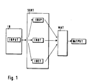
- FIG. 1 a very schematic arrangement is shown, based on which the method according to the invention can be exemplified, a more detailed Representation of the invention is based on resources one Telecommunication device explained later.
- input data INPUT are detected.
- the Input device IN can e.g. a graphical user interface or a Keyboard.
- the input data INPUT relate to data which are for a Communication relationship are required, e.g. a phone number or an email address of a desired communication partner, an Indication that voice data are to be sent and an indication that the data may also reach the communication partner with a delay.
- the Input data INPUT are then sent from the input device IN to a Grouping device SORT transmits, illustrated by an arrow that the Data flow of the input data INPUT to the grouping device SORT implies.
- the grouping device SORT then groups them INPUT input data into groups of data by adding an affiliation of the individual components of the input data INPUT either to a first Data group INKP or to a second data group INDT or to one third data group INCT determined.
- the process of grouping is through three arrows illustrating the path of the input data INPUT into the indicate individual data groups INKP, INDT and INCT.
- In the first Data group INKP are those of the grouping device SORT Input data INPUT grouped that have characteristics that the relate to the communication partner involved in the communication relationship.
- the grouping device SORT groups those of the input data INPUT a to be transferred within the framework of the communication relationship Data types relate, in the example above, to the specification that voice data are shipping.
- the SORT grouping organizes those the input data INPUT to the third data group INCT, which is a possible connection type of the desired communication relationship concern, in the example, the indication that the data is also delayed to the Communication partners may access.
- the grouping device SORT then sends input data INPUT to one Processing device MAT further.
- Three separate arrows in FIG. 1 clarifies that the input data INPUT pre-grouped into three Data streams get into the processing device MAT, which through a Reference to one of the three data groups INKP, INDT and INCT can be distinguished.
- Such an indication can e.g. an identifier be that the grouping device SORT to the individual components of the INPUT input data before being sent to the processing device MAT adds and the data as one of the data groups INKP, INDT and INCT associated.
- the processing device MAT can use a decision matrix the INKP, INDT and INCT data groups received by it Implement output data OUTPUT, which the characteristics of a Communication relationship included that the INPUT through the input data specified requirements met. With the output data OUTPUT can then the desired communication relationship from one Telecommunications equipment manufactured or an existing one Communication relationship can be modified.
- Such output data can e.g. to instruct to meet specified requirements at a Provider of telecommunications services Communication link with a certain minimum transmission rate to request, data to be sent due to restricted Evaluation options in the telecommunications facility of the Convert communication partner into a predetermined data format and tag this data before sending it so that it can be the receiving telecommunication device to one for the data suitable data sink.
- Decision matrix DEC An example of a particularly simple decision matrix called Decision matrix DEC, is shown in Figure 2.
- the columns of the Decision matrix DEC are from left to right with the Marked indices S1, S2, S3, S4 and S5.
- the rows of Decision matrix DEC carry the from top to bottom Reference symbols RKP, RDT and RCT and ROUTPUT, which correspond to those from FIG known names of the data groups INKP, INDT and INCT as well as the Correlate output data OUTPUT.
- the RKP, RDT and RCT series include the following more detailed feature indices are entered, each on Features indicate the data from those known from FIG Data groups INKP, INDT and INCT can have.
- the bottom row of the Decision matrix DEC shows feature groups that all features contain the data known as output data OUTPUT from FIG. 1 also wear.
- Row RDT in the decision matrix DEC are data types to be transmitted entered, as an example in columns S2 and S4 a feature index VOICE, which indicates voice data, and in columns S3 and S5 Feature index PICT, which characterizes image data.
- the one below RCT series which is a possible connection type of the desired Concerns communication relationship, contains one in column S2 Feature index DIRECT, which instructs the immediate transfer of data, and a feature index DELAY, which gives permission for a delayed Transfer of data displays in columns S3, S4 and S5.
- the ROUTPUT row of the DEC decision matrix contains groups of characteristics called OUT1, OUT2, OUT3 and OUT4.
- the Feature group OUT1 a direct connection to a telephone describe the feature group OUT2 an e-mail data transfer that Feature group OUT3 a connection to a voicebox and the Feature group OUT4 a connection to a fax machine.
- FIG Processing device MAT the decision matrix DEC as Decision matrix used.
- the processing device receives the processing device MAT into the INKP, INDT and INCT data groups from the SORT grouping facility pre-grouped input data, the processing device MAT the in characteristics contained in this input data with the characteristics of Compare feature indices of the decision matrix DEC.
- the input data the grouping device SORT compares the first data group INKP with the Feature indices of the RKP series, the input data of the second data group INDT with the feature indices of the RDT series and the input data of the third data group INCT with the feature indices of the RCT series.
- the reads Processing device MAT the specified in this column Feature group OUT1, OUT2, OUT3 or OUT4 and forms from them Characteristics of the output data OUTPUT.
- the participant number is included with regard to the first data group INKP of a desired communication partner, with regard to the second Data group INDT an indication that voice data are to be transmitted, and with regard to the third data group INCT a release that the to transmitted data may also be transmitted with a delay, then determined the processing device MAT by comparing that this needs are fulfilled by the feature groups in column S4. Then she reads Processing device MAT that specified in column S4 Characteristic group OUT3 and generates the from their characteristics Output data OUTPUT, which, as mentioned, connects to a voicebox describe.
- the processing device MAT would have when comparing the input data the feature indices of the RKP, RDT and RCT series found that the The requirements of the input data are met by the information in column S1 and then the output data OUTPUT with the characteristics of the Feature group OUT formed.
- the decision matrix DEC from FIG. 2 is off A particularly simple variant for the sake of a descriptive description a decision matrix. Much more detailed configurations of a Decision matrix can be changed at any time according to the respective requirements be formed.
- the decision matrix DEC can e.g. for more columns be expanded into the further characteristics of the data groups INKP, INDT and INCT each in groups of three and resulting from each Output data OUTPUT can be entered.
- the decision matrix DEC can also be in a decision tree with individual "If-Then" decision steps are resolved, which then e.g. in a Computer program is implementable.
- a communication partner can also use the available means are marked, e.g. by means for the use of various transmission media or through equipment with software for receiving or sending certain types of data.
- the connection type describes whether the communication partner is for Communication must be present (on-line) or not present (off-line), e.g. on-line for a conversation, off-line for later evaluable data.
- About the Connection type can e.g. also a constant or a dynamic adapting transmission rate in a certain amount on a Connection may be required.
- the data type allows "finite" data (e.g. data file) from "infinite” data (e.g. conversation) become.
- the grouping device SORT and the processing device MAT is shown as separate devices and explained in their function. In practice, however, both institutions can be combined. E.g. can a processor for data processing both the Functions of the grouping device SORT and the Execute the processing device MAT if it is the one to be executed required command sequences are supplied.
- the functions of the grouping device SORT and the functions of Processing device MAT each as separate programs or Program functions created. With the program function for the Grouping device SORT can then the processor into the input data Pre-group data groups INKP, INDT and INCT and pre-group them Write form to memory. The processor can then do this remove the pre-grouped data from the memory and use the Program function of the processing device MAT in the described Process further.
- FIG. 3 shows a terminal TER according to the invention, via which Communication relationships can be established and maintained.
- the Terminal TER can e.g. be a comfortable telephone, over which too further communication relationships that go beyond pure telephony are possible, e.g. Communication with the internet.
- the terminal TER can but also be a personal computer over the phone and Fax transmission, as well as more modern forms of communication, such as e-mail Services and internet communication are feasible.
- Other designs of the Terminal TER are also conceivable, e.g. that of a universally applicable so-called "personal communicator", with which one can different Telecommunication networks, mobile telecommunication networks or wired telecommunication networks, also with different ones Scope of services offered.
- the invention has proven to be very useful because of the extensive and the potential of such a user is often too difficult to use "Personal Communicator" as in the following sections becomes clear, simple, efficient and therefore usable.
- the terminal TER has a communication interface COM, via which the terminal TER two different communication paths CONA and CONB can address that, for example, not in Figure 3 communication channels shown are available.
- the representation different Communication paths in FIG. 3 serve only as separate paths Vividness.
- the Communication channels CONA and CONB are quite different Communication media are meant, e.g. two physically separate Subscriber lines of a telecommunications network. It is the same but possible that on one and the same medium, e.g. on a Subscriber line several forms of communication alternatively or can be run at the same time. For example, on the mentioned Subscriber line on a channel a telephone connection be maintained and at the same time an email on another channel be sent. This is e.g. possible if the subscriber line belongs to an ISDN telecommunications network.
- the communication interface COM is controlled by a control means CPU controlled.
- the control means CPU has the communication interface COM how to select and use the CONA and CONB communication channels are useful.
- the control means CPU can e.g. be a processor that Command sequences from a memory MEM, which also in Figure 3 is shown.
- the control means CPU can use the memory MEM for storage of data.
- the control means CPU both the functions of the grouping device SORT known from FIG. 1 as well as perceive the processing device MAT.
- an input device INTER is shown in FIG Function corresponds to the input device IN known from FIG. 1. So data is also acquired by the input device INTER, which for a Communication relationship are required.
- the input device INTER can e.g. be a simple keypad with, for example, a name or a telephone number of a desired communication partner and one Key command sequence as a reference to the under the Communication relationship to be transferred data types can.
- the Input device INTER advantageously a graphical user interface that can be operated using a mouse.
- the embodiment of the input device INTER as graphical user interface only as a pure input interface described.
- FIG. 4 A possible, schematic embodiment of such a graphic
- the user interface is shown as a graphical user interface U1 in FIG. 4.
- the illustration in FIG. 4 is limited to a possible design of the graphic output of the user interface Ul, e.g. on a monitor. medium for entering data, e.g. a keypad and a mouse, and means for Control of the user interface Ul, e.g. a processor and a memory are in Figure 4 not shown separately.
- the user interface Ul is roughly in two Main fields divided, referred to as the source field SRC and as the target field TAR are.
- the source field SRC shows elements that are representative of Components of the input data INPUT known from FIG. 1 are available.
- the Elements K1 and K2 are each a graphic representation, that is, a symbol or a so-called "icon" for a possible communication partner. On such symbol can e.g. be a picture of the partner or an entry of some kind graphically implemented notebook.
- the User interface Ul also other elements, not shown in Figure 4 have, each for other communication partners or for different communication options can be available via the one Communication partner, e.g. via a communication option with a mobile terminal and a communication option with a wired fax machine. For this, e.g. an image of each Communication partner as an icon on the user interface Ul, that the communication partner together with a mobile terminal or with a fax machine.
- the use of elements K1 and K2 and further elements of the user interface Ul to be explained explained in detail later.
- the elements are K1 and K2 already combined in a field SRCKP, in which only elements who are involved in the communication relationship Symbolize communication partners and thus the one known from FIG. 1 Belong to the INKP data group.
- a field SRCCT elements that are symbols for Data from the INCT data group serve as a possible Connection type of the desired communication relationship.
- the Element CT1 can e.g. be designed in the form of a letter symbol and thus point out that data to be sent in an offline communication may reach the communication partner with a delay.
- Element CT2 can e.g. be determined that within a Online connection should be communicated because voice information in the Should be exchanged during a conversation or because of a Data exchange sequence with immediate acknowledgment of received data is required.
- the function of the element CT2 is e.g. recognizable by using an image of a telephone for the element CT2 becomes.
- the division of the source field SRC into the fields SRCKP, SRCDT and SRCCT analogous to the INKP, INDT and INCT data groups and Pre-grouping of the elements K1, K2, DT1, DT2, CT1 and CT2 into these fields serves for a clear representation for the user and allows the user to as explained in more detail below, the Input data INPUT into the terminal TER.
- This pre-grouping Although it is advantageous, it is not absolutely necessary since the aforementioned Elements within the source field SRC also distributed unstructured or after other aspects can be ordered. For example, Groups of Input data with one element each from the data groups INKP, INDT and INCT be formed within the source field SRC by a user the user interface Ul are often used and therefore already are available in groups for use.
- the elements K1, K2, DT1, DT2, CT1 and CT2 can be taken from the source field SRC selected and the target field TAR e.g. with the help of a mouse in shape a so-called “drag-and-drop” mouse action, in which marked an element with the mouse, "dragged" to a target and there "dropped".
- Such procedures with a mouse are everyone User of a graphically oriented operating system for a staff Computers, e.g. Windows from Microsoft, well known.
- the Mouse actions are indicated in FIG. 4 by arrows which appear as mouse action M1, Mouse action M2 and mouse action M3 are designated.
- the user leads through one of the mouse actions M1, M2 or M3 one element K1, K2, DT1, DT2, CT1 and CT2 each to the target field TAR.
- the target field TAR then captures the three from the user in this way selected items. This means that all are one for a classification Communication relationship necessary characteristics defined. However, it is also possible that from the data groups INKP, INDT and INCT each more than an item is selected. For example, a communication relationship not just be wanted with a communication partner, but one Conference call with two or more communication partners required become.
- the user can then e.g. both elements K1 and K2 from the field SRCKP in the target field TAR and thus the desire for one simultaneous communication relationship with both, each through this Sign elements symbolized communication partners.
- the user interface can be the last of the accept competing entries as valid or the user through a Make the message aware of the error and make a correct entry prompt.
- the user interface Ul advantageously checks whether within the Target field TAR all for classifying a communication relationship necessary elements are included before the user interface Ul with the Further processing of the characteristics continues by the in the target field TAR contained elements are described.
- the user interface Ul requests the If necessary, the user can enter missing elements or add them independently complementary features that are typically added to by the user features already selected can be combined. Even through one suitable design and functionality of the user interface Ul can Users are guided to classify all of them Communication relationship necessary elements from the source field SRC in'das Target field to draw TAR.
- the target field TAR can be divided into target subfields the fields SRCKP, SRCDT and SRCCT of the source field SRC correspond.
- the user interface Ul immediately arranges the respective element that of the target subfields that correspond to the SRCKP, SRCDT or SRCCT field corresponds to the origin of the stored element. This will When looking at the target field TAR, users can easily see which of the Target subfields are not yet occupied by an element and therefore which one Entry still has to be made so that all for a classification of required characteristics exist are.
- the User interface Ul independently with the further processing of the entered Start data or be instructed to do so by the user, e.g. by Pressing a button on one of the user interfaces Ul Keypad or by "pressing" a "start button” on the User interface Ul, i.e. by selecting and activating a mouse click field of the user interface Ul not shown in FIG. 4.
- the User interface Ul With help of its own control means and its own memory can User interface Ul the functions of those known from FIG. 1 Grouping device SORT and the processing device MAT meet.
- the User interface Ul then groups the input data into the Data groups INKP, INDT and INCT enter the pre-grouped Input data in a decision matrix and wins from the Decision matrix then output data.
- This output data gives the User interface Ul forward to a telecommunications device. Based the telecommunication device can output the output data from the User defined communication relationship on the user interface Ul build or modify an existing communication relationship.
- the user interface Ul is part of the input device INTER and so that the terminal is TER, the user interface Ul can be that of the User entered input data directly from the target field TAR Pass on facilities of the terminal TER for further processing.
- the user interface must then have the functions of the grouping device SORT and the processing device MAT itself, but can transfer these functions to devices of the terminal TER. Such one further procedure is described below with reference to FIG. 3 executed.
- the input device INTER After the input device INTER all for a classification of one Communication relationship required characteristics as input data has determined, the input device INTER provides this input data Further processing to the control means CPU. This loads from the MEM memory various command sequences, according to their instructions the Control means CPU further processes the input data.
- the control means CPU groups as already explained in connection with FIG. 1, the Input data into the INKP, INDT and INCT data groups, e.g. by that Control means CPU compares the input data with features, the data as classify according to the respective data groups and which in the MEM memory are stored. That gives the data sorted by data groups Control means CPU in a decision matrix, e.g. into that of Figure 2 known decision matrix DEC, and determines the one for the user required communication relationship required characteristics.
- a decision matrix e.g. into that of Figure 2 known decision matrix DEC
- control means CPU can then determine which of the Communication channels CONA or CONB to the needs of the user corresponds and depending on the result, the communication interface COM instruct to activate the communication path CONA or the CONB.
- the communication path CONB e.g. the communication path CONB from the Communication interface COM and thus used by the terminal TER.
- the communication path CONB is therefore a solid line shown.
- the invention also has an advantageous effect if it is not only for construction a suitable communication relationship is used, but also for Modification of an existing communication relationship.
- the Terminal TER can with changing framework conditions, e.g. at a transmission of an e-mail following a voice connection and the same communication partner, one already for the Voice transmission used communication relationship to the requirements adapt the e-mail transmission. This will be done during the Voice transmission for the classification of the desired Features required for e-mail transmission from the terminal TER the input device INTER determined.
- the terminal TER more precisely that Control means CPU, groups these new input data in the already explained in the data groups INKP, INDT and INCT and wins With the help of the decision matrix, the initial characteristics for a Redesign of the communication relationship necessary for a transfer of the Email should be suitable.
- Control means CPU then to the communication interface COM existing communication relationship according to the determined Modify basic characteristics for an e-mail transmission.
- the Communication interface COM sends e.g. to the Telecommunication device of the communication partner an identifier, on the basis of which this telecommunications device can recognize that the Subsequently sent data are not voice data, but an email included and therefore to another data sink within the Telecommunication device should arrive as the voice data.
- FIG. 5 shows a node NODE which is in a Telecommunications network can be used.
- the node NODE shows essential functions and functions Components that already exist in principle from the terminal TER from FIG are known, namely the memory MEM, the control means CPU and the COM communication interface.
- the memory MEM and the control means CPU as components of the node NODE a larger one Efficiency than as components of the terminal TER.
- the Communication interface COM is at the node NODE by one Communication path CONSRC expanded, which also does not shown terminal or node leads.
- the Communication interface COM can use the communication path CONSRC with the communication path CONA or CONB alternatively or at the same time connect.
- the communication interface COM can e.g. a switching matrix his.
- the communication links CONSRC, CONA and CONB are in place exemplary of other, not shown in Figure 5 Communication links. As in connection with Figure 3 already the communication connections CONA and CONB are explained as well the communication path CONSRC exemplary representations for different physical paths, but also for different ones Forms of communication can stand.
- the node NODE does not have a separately designed input device INTER. Instead, the node NODE is used to classify a Communication relationship required characteristics in the form of Input data from one via the communication path CONSRC connected telecommunication device, e.g. a terminal or a node, transmitted to the communication interface COM and from forwarded there to the control means CPU.
- the Communication interface COM and the control means CPU then fulfill together a function comparable to the input device INTER Function, namely the determination of the required input data.
- the Terminal only serves here as an interface device for recording the Input data for which e.g. a keypad or a user interface of the Terminal is used.
- the node NODE is instructed by the input data to perform a Communication relationship from the communication path CONSRC starting from there or one already starting from there Modify communication relationship.
- the received input data groups the control means CPU according to instructions from the memory MEM loaded command sequences in the data groups INKP, INDT and INCT and loads a decision matrix from the memory MEM into which the Control means CPU then inputs the pre-grouped input data.
- the control means CPU obtains output data from this decision matrix those for making or modifying any of that Communication path CONSRC outgoing communication relationship required are.
- the Control means CPU the communication interface COM e.g. to the Communication path CONSRC with the communication path CONB connect.
- the functions of the grouping device SORT and the processing device MAT from FIG. 1 can be carried out by the control means CPU known from FIGS. 3 and 5 in cooperation with the memory MEM by loading and executing command sequences.
- the control means CPU known from FIGS. 3 and 5
- These command sequences are usually coded in a programming language, for example the high-level language 'C' or the object-oriented programming language 'C ++', and compiled into a machine language which can be read and executed by the control means.
- the program module according to the invention is divided into individual functional units, as will be explained in the following, these functional units are still connected to one another after compiling by a so-called "linking", so that the transitions and branches between the individual functional units, the so-called program jumps the control means can be traced during the execution of the program module.
- the control means is, for example, a processor of a personal computer or a telecommunication device.
- the program module can be stored in the memory and can be read there by the control means in order to execute the command sequences.
- the memory may, for example, a magnetic memory, such as a floppy disk or a hard disk, or be an electronic memory such as an EEPROM (E lectrical E rasable P rogrammable R ead o nly M emory), which is often used in telecommunication terminals.
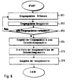
- An example of such a program module is shown in FIG. 6 as program module PRG.
- program module PRG An example of such a program module is shown in FIG. 6 as program module PRG.
- the program module PRG is stored in a memory of a telecommunication device and is executed by a control means of this telecommunication device.
- the program module PRG is in the interest of an easy to understand presentation shown in Figure 6 in the form of a flow chart, in the course of which individual Steps are performed.
- the individual steps stand for one Command or a sequence of commands, each a functional unit, a so-called function. This functional separation is true practical, but not absolutely necessary.
- the program module PRG can also as a single function of a higher-level program for Build or modify a communication relationship.
- Step ST1 is for classifying a communication relationship required input data.
- Input means and output means from the control means the instructions of the Controlled following step ST1.
- the instructions of step ST1 are in an input functional unit, e.g. in a subroutine, summarized.
- the input data thus acquired are stored in a step ST2 into the data groups INKP, INDT and INCT known from FIG. 1 grouped.
- the instructions of step ST2 are one Grouping unit, also e.g. to a program function, bundled. This is then checked in an optional step ST3, whether in step ST1 for each of the data groups INKP, INDT and INCT an entry date has been recorded.
- step ST3 is not in the Program module should be included, it is also possible that the input data already from the input function unit in step ST1 to one of the Input means are offered for input in such a form that a incorrect or incomplete entry becomes impossible.
- Input means should be designed so that only a complete set of Input data is offered for input and only as a complete set of can be entered by a user.
- a complete set of input data contains an entry date from the data groups INKP, INDT and INCT. Or the telecommunication device, e.g.
- Step ST3 Node receives node from a second telecommunication device in each case a complete set of input data where the second Telecommunications equipment has to ensure that each one Date of receipt from the INKP, INDT and INCT data groups in one complete sentence is included.
- Another way to do without Step ST3 results when in step ST1 from the input function unit already as a default, a so-called default value Date of receipt from data groups INKP, INDT and INCT provided which is optionally overridden by a user suitable date of receipt changed, but also unchanged in the Step ST2 can be adopted.
- Step ST4 the pre-grouped input data are combined in one Step ST4 is entered into a decision matrix included in the command sequence of step ST4 as "if-then" decision step sequence can, but also as a separate data structure in the memory of the Telecommunication device can be filed. From the Decision matrix are then determined in a step ST5 output values, the one desired by the entry in step ST1 Characterize communication relationship. Steps ST3, ST4 and ST5 are shown in FIG. 6 for better understanding as discrete steps, but can also easily become a processing functional unit be summarized, in particular because none of these Steps from a branch is required.
- Step ST6 The output values determined in step ST5 are in an optional Step ST6 issued, e.g. to another, not shown in Figure 6 Program module, which then creates the desired one with the help of further command sequences Establishes communication relationship.
- Step ST5 without step ST6, the determined output values from the Decision matrix are not output but only in the Memory of the telecommunications device an index, a so-called "Pointer" is stored, which indicates the determined output values.
- Step ST5 without step ST6, the determined output values from the Decision matrix are not output but only in the Memory of the telecommunications device an index, a so-called "Pointer" is stored, which indicates the determined output values.
- Step ST5 without step ST6, the determined output values from the Decision matrix are not output but only in the Memory of the telecommunications device an index, a so-called "Pointer" is stored, which indicates the determined output values.
- Pointer a so-called "Pointer”
- a superordinate calling the program module PRG Control program of the telecommunications device read out the index and so directly to the storage space within the storage area of the Access the decision matrix that contains the determined output values.
- a step end which follows the step ST6, ends the process of Program modules.
Applications Claiming Priority (2)
| Application Number | Priority Date | Filing Date | Title |
|---|---|---|---|
| DE19834321A DE19834321A1 (de) | 1998-07-30 | 1998-07-30 | Verfahren, Endgerät, Knoten, Programmodul und Bedienoberfläche zur Ermittlung von für eine Kommunikationsbeziehung erforderlichen Merkmalen |
| DE19834321 | 1998-07-30 |
Publications (3)
| Publication Number | Publication Date |
|---|---|
| EP0977416A2 true EP0977416A2 (fr) | 2000-02-02 |
| EP0977416A3 EP0977416A3 (fr) | 2004-01-21 |
| EP0977416B1 EP0977416B1 (fr) | 2006-09-20 |
Family
ID=7875819
Family Applications (1)
| Application Number | Title | Priority Date | Filing Date |
|---|---|---|---|
| EP99440208A Expired - Lifetime EP0977416B1 (fr) | 1998-07-30 | 1999-07-23 | Méthode, terminal, noeud, module programme et interface d'exploitation pour déterminer des caractéristiques requises pour une application de communication |
Country Status (9)
| Country | Link |
|---|---|
| US (1) | US6711584B1 (fr) |
| EP (1) | EP0977416B1 (fr) |
| JP (1) | JP4066217B2 (fr) |
| CN (1) | CN1127250C (fr) |
| AT (1) | ATE340477T1 (fr) |
| AU (1) | AU748482B2 (fr) |
| CA (1) | CA2279057A1 (fr) |
| DE (2) | DE19834321A1 (fr) |
| SG (1) | SG87045A1 (fr) |
Cited By (1)
| Publication number | Priority date | Publication date | Assignee | Title |
|---|---|---|---|---|
| WO2006024625A1 (fr) * | 2004-09-03 | 2006-03-09 | Siemens Aktiengesellschaft | Terminal de communication comportant un ecran et eventuellement un systeme de commande d'affectations entre des applications et des interfaces de communication |
Families Citing this family (11)
| Publication number | Priority date | Publication date | Assignee | Title |
|---|---|---|---|---|
| DE10230093A1 (de) * | 2002-07-04 | 2004-02-05 | Siemens Ag | Verfahren zur automatischen Löschung mindestens eines aktivierten Feldelements einer Bedienoberfläche einer Computeranwenderstation |
| EP1463246A1 (fr) * | 2003-03-27 | 2004-09-29 | Motorola Inc. | Communication de données conversationnelles entre terminaux sur une liaison radio |
| US20150248690A1 (en) * | 2014-03-03 | 2015-09-03 | International Business Machines Corporation | Cost Optimization for Bundled Licenses |
| CA2902093C (fr) | 2014-08-28 | 2023-03-07 | Kevin Alan Tussy | Procede d'authentification de reconnaissance faciale comprenant des parametres de chemin |
| US10803160B2 (en) | 2014-08-28 | 2020-10-13 | Facetec, Inc. | Method to verify and identify blockchain with user question data |
| US10698995B2 (en) | 2014-08-28 | 2020-06-30 | Facetec, Inc. | Method to verify identity using a previously collected biometric image/data |
| US11256792B2 (en) | 2014-08-28 | 2022-02-22 | Facetec, Inc. | Method and apparatus for creation and use of digital identification |
| US10614204B2 (en) | 2014-08-28 | 2020-04-07 | Facetec, Inc. | Facial recognition authentication system including path parameters |
| US10915618B2 (en) | 2014-08-28 | 2021-02-09 | Facetec, Inc. | Method to add remotely collected biometric images / templates to a database record of personal information |
| USD987653S1 (en) | 2016-04-26 | 2023-05-30 | Facetec, Inc. | Display screen or portion thereof with graphical user interface |
| CN116094943B (zh) * | 2023-04-07 | 2023-06-06 | 湖南快乐阳光互动娱乐传媒有限公司 | 一种pcdn节点重要性排名方法、装置和设备 |
Citations (4)
| Publication number | Priority date | Publication date | Assignee | Title |
|---|---|---|---|---|
| EP0281102A2 (fr) * | 1987-03-02 | 1988-09-07 | Wang Laboratories Inc. | Methode et appareil pour spécifier des paramètres de communication |
| JPH02270466A (ja) * | 1989-04-12 | 1990-11-05 | Toshiba Corp | 通信メディア自動選択装置 |
| JPH03101452A (ja) * | 1989-09-14 | 1991-04-26 | Matsushita Graphic Commun Syst Inc | データ通信端末装置 |
| EP0529207A1 (fr) * | 1991-06-05 | 1993-03-03 | Robert Bosch Gmbh | Méthode pour la commande et la surveillance d'un réseau de télécommunication |
Family Cites Families (11)
| Publication number | Priority date | Publication date | Assignee | Title |
|---|---|---|---|---|
| DE2240557A1 (de) * | 1971-08-18 | 1973-02-22 | Jean Albert Dreyfus | Spracherkennungsvorrichtung zum steuern von maschinen |
| US3851109A (en) * | 1973-05-03 | 1974-11-26 | R Downs | Telephone control system |
| LU87095A1 (de) * | 1987-06-11 | 1988-04-05 | Siemens Ag | Schaltungsanordnung fuer eine zentralgesteuerte fernmeldevermittlungsanlage,insbesondere pcm-fernsprechvermittlungsanlage,mit einem zentralteil und mit diesem verbundenen anschlussgruppen |
| EP0306855A3 (fr) * | 1987-09-08 | 1990-08-22 | Siemens Aktiengesellschaft | Agencement pour charger les paramètres dans des modules actifs d'un système ordinateur |
| DE3823914A1 (de) * | 1988-07-14 | 1990-01-18 | Siemens Ag | Verfahren zum uebermitteln endgeraetebestimmender programmparameterdaten von einer kommunikationsanlage zu kommunikationsendgeraeten |
| JPH02195400A (ja) * | 1989-01-24 | 1990-08-01 | Canon Inc | 音声認識装置 |
| JPH04271542A (ja) * | 1991-02-27 | 1992-09-28 | Nec Corp | データ伝送回路 |
| SE515274C2 (sv) * | 1992-11-09 | 2001-07-09 | Ericsson Telefon Ab L M | Paketväljare för telekommunikationsanläggning |
| CA2139081C (fr) * | 1994-12-23 | 1999-02-02 | Alastair Gordon | Systeme et methode de messagerie unifies |
| US5749066A (en) * | 1995-04-24 | 1998-05-05 | Ericsson Messaging Systems Inc. | Method and apparatus for developing a neural network for phoneme recognition |
| US6097930A (en) * | 1998-08-21 | 2000-08-01 | Weblink Wireless, Inc. | System and method for modeling simulcast delay spread and optimizing launch delays |
-
1998
- 1998-07-30 DE DE19834321A patent/DE19834321A1/de not_active Ceased
-
1999
- 1999-07-23 AT AT99440208T patent/ATE340477T1/de not_active IP Right Cessation
- 1999-07-23 EP EP99440208A patent/EP0977416B1/fr not_active Expired - Lifetime
- 1999-07-23 DE DE59913855T patent/DE59913855D1/de not_active Expired - Lifetime
- 1999-07-28 SG SG9903656A patent/SG87045A1/en unknown
- 1999-07-28 JP JP21417699A patent/JP4066217B2/ja not_active Expired - Fee Related
- 1999-07-29 CA CA002279057A patent/CA2279057A1/fr not_active Abandoned
- 1999-07-29 US US09/362,735 patent/US6711584B1/en not_active Expired - Fee Related
- 1999-07-30 CN CN99111912A patent/CN1127250C/zh not_active Expired - Fee Related
- 1999-07-30 AU AU42408/99A patent/AU748482B2/en not_active Ceased
Patent Citations (4)
| Publication number | Priority date | Publication date | Assignee | Title |
|---|---|---|---|---|
| EP0281102A2 (fr) * | 1987-03-02 | 1988-09-07 | Wang Laboratories Inc. | Methode et appareil pour spécifier des paramètres de communication |
| JPH02270466A (ja) * | 1989-04-12 | 1990-11-05 | Toshiba Corp | 通信メディア自動選択装置 |
| JPH03101452A (ja) * | 1989-09-14 | 1991-04-26 | Matsushita Graphic Commun Syst Inc | データ通信端末装置 |
| EP0529207A1 (fr) * | 1991-06-05 | 1993-03-03 | Robert Bosch Gmbh | Méthode pour la commande et la surveillance d'un réseau de télécommunication |
Non-Patent Citations (2)
| Title |
|---|
| PATENT ABSTRACTS OF JAPAN vol. 015, no. 026 (E-1025), 22. Januar 1991 (1991-01-22) & JP 02 270466 A (TOSHIBA CORP), 5. November 1990 (1990-11-05) * |
| PATENT ABSTRACTS OF JAPAN vol. 015, no. 288 (E-1092), 22. Juli 1991 (1991-07-22) & JP 03 101452 A (MATSUSHITA GRAPHIC COMMUN SYST INC), 26. April 1991 (1991-04-26) * |
Cited By (1)
| Publication number | Priority date | Publication date | Assignee | Title |
|---|---|---|---|---|
| WO2006024625A1 (fr) * | 2004-09-03 | 2006-03-09 | Siemens Aktiengesellschaft | Terminal de communication comportant un ecran et eventuellement un systeme de commande d'affectations entre des applications et des interfaces de communication |
Also Published As
| Publication number | Publication date |
|---|---|
| SG87045A1 (en) | 2002-03-19 |
| ATE340477T1 (de) | 2006-10-15 |
| AU4240899A (en) | 2000-02-24 |
| EP0977416B1 (fr) | 2006-09-20 |
| AU748482B2 (en) | 2002-06-06 |
| CN1127250C (zh) | 2003-11-05 |
| JP4066217B2 (ja) | 2008-03-26 |
| CN1248121A (zh) | 2000-03-22 |
| CA2279057A1 (fr) | 2000-01-30 |
| JP2000156719A (ja) | 2000-06-06 |
| DE19834321A1 (de) | 2000-02-03 |
| DE59913855D1 (de) | 2006-11-02 |
| EP0977416A3 (fr) | 2004-01-21 |
| US6711584B1 (en) | 2004-03-23 |
Similar Documents
| Publication | Publication Date | Title |
|---|---|---|
| DE60029321T2 (de) | Verfahren und vorrichtung zur fernbedienung eines hausnetzwerks von einem externen kommunikationsnetz | |
| DE60206741T2 (de) | Kommunikationsmodul zur steuerung von betriebsabläufen einer pbx | |
| EP0520083B1 (fr) | Protection de la consistance des données dans un système de télécommunications numériques | |
| EP1430369B1 (fr) | Acces dynamique a des ressources d'automatisation | |
| EP0977416B1 (fr) | Méthode, terminal, noeud, module programme et interface d'exploitation pour déterminer des caractéristiques requises pour une application de communication | |
| EP1282296A2 (fr) | Méthode et dispositif pour établir un circuit de conférence | |
| DE69332927T2 (de) | Gerät zur Verwaltung eines Elementverwalters für ein Fernmeldevermittlungssystem | |
| EP1547353B1 (fr) | Procede pour fournir une information concernant une absence | |
| EP0942613A2 (fr) | Méthode d'administration des données d'abonnés de services de télécommuncation ainsi que serveur et central téléphonique y afférant | |
| EP1062790B1 (fr) | Procede pour detecter et traiter des informations servant a etablir une communication telephonique dans un systeme ito (integration telephonique par ordinateur), et systeme ito correspondant | |
| DE69912456T2 (de) | Verfahren und Vorrichtung zur Steuerung einer Fernmeldekonferenz | |
| EP1005216B1 (fr) | Procédé et système pour validation des données de configuration pour systèmes de télécommunication | |
| EP1005215A2 (fr) | Procédé et système pour l'édition des données de configuration pour systèmes de télécommunication | |
| EP0619682B1 (fr) | Procédé pour l'administration d'installations de communication | |
| DE19523537A1 (de) | Verfahren und Anordnung zur Steuerung von Leistungsmerkmalen einer Vermittlungsstelle | |
| DE69634953T2 (de) | Anpassbare anwenderschnittstelle | |
| EP0991225A2 (fr) | Procédé, serveur et terminal pour la modification des données de service stockés sur un serveur | |
| WO2007009884A2 (fr) | Procede de configuration dynamique de services dans un systeme technique | |
| EP2249219A2 (fr) | Procédé de sélection d'un système de communication agencé dans un réseau de transmission d'un système d'automatisation | |
| EP1316865A1 (fr) | Système en service d'automatisation | |
| DE10310886B3 (de) | Verfahren und System zum gleichzeitigen Anzeigen desselben Inhalts auf zu verschiedenen Computern gehörenden Bildschirmen, sowie Web-Seite mit einem Link zu einem Dienst | |
| WO2000008828A1 (fr) | Telephone a surface de commande pouvant etre configuree | |
| EP3361680A1 (fr) | Système d'automatisation de communication destiné à la transmission bilatérale de données de message et produit-programme d'ordinateur et procédé de traitement de données de message et utilisation | |
| DE102006015057A1 (de) | Benutzerschnittstelle zur Herstellung einer Kommunikations-Verbindung | |
| EP1279300B1 (fr) | Gestion coordonnee de centraux telephoniques au niveau d'un reseau |
Legal Events
| Date | Code | Title | Description |
|---|---|---|---|
| PUAI | Public reference made under article 153(3) epc to a published international application that has entered the european phase |
Free format text: ORIGINAL CODE: 0009012 |
|
| AK | Designated contracting states |
Kind code of ref document: A2 Designated state(s): AT BE CH CY DE DK ES FI FR GB GR IE IT LI LU MC NL PT SE |
|
| AX | Request for extension of the european patent |
Free format text: AL;LT;LV;MK;RO;SI |
|
| PUAL | Search report despatched |
Free format text: ORIGINAL CODE: 0009013 |
|
| AK | Designated contracting states |
Kind code of ref document: A3 Designated state(s): AT BE CH CY DE DK ES FI FR GB GR IE IT LI LU MC NL PT SE |
|
| AX | Request for extension of the european patent |
Extension state: AL LT LV MK RO SI |
|
| RIC1 | Information provided on ipc code assigned before grant |
Ipc: 7H 04M 3/42 A |
|
| 17P | Request for examination filed |
Effective date: 20031208 |
|
| 17Q | First examination report despatched |
Effective date: 20040428 |
|
| AKX | Designation fees paid |
Designated state(s): AT BE CH CY DE DK ES FI FR GB GR IE IT LI LU MC NL PT SE |
|
| GRAP | Despatch of communication of intention to grant a patent |
Free format text: ORIGINAL CODE: EPIDOSNIGR1 |
|
| RAP1 | Party data changed (applicant data changed or rights of an application transferred) |
Owner name: NAXOS DATA LLC |
|
| GRAS | Grant fee paid |
Free format text: ORIGINAL CODE: EPIDOSNIGR3 |
|
| GRAA | (expected) grant |
Free format text: ORIGINAL CODE: 0009210 |
|
| AK | Designated contracting states |
Kind code of ref document: B1 Designated state(s): AT BE CH CY DE DK ES FI FR GB GR IE IT LI LU MC NL PT SE |
|
| PG25 | Lapsed in a contracting state [announced via postgrant information from national office to epo] |
Ref country code: NL Free format text: LAPSE BECAUSE OF FAILURE TO SUBMIT A TRANSLATION OF THE DESCRIPTION OR TO PAY THE FEE WITHIN THE PRESCRIBED TIME-LIMIT Effective date: 20060920 Ref country code: IT Free format text: LAPSE BECAUSE OF FAILURE TO SUBMIT A TRANSLATION OF THE DESCRIPTION OR TO PAY THE FEE WITHIN THE PRE;WARNING: LAPSES OF ITALIAN PATENTS WITH EFFECTIVE DATE BEFORE 2007 MAY HAVE OCCURRED AT ANY TIME BEFORE 2007. THE CORRECT EFFECTIVE DATE MAY BE DIFFERENT FROM THE ONE RECORDED.SCRIBED TIME-LIMIT Effective date: 20060920 Ref country code: IE Free format text: LAPSE BECAUSE OF FAILURE TO SUBMIT A TRANSLATION OF THE DESCRIPTION OR TO PAY THE FEE WITHIN THE PRESCRIBED TIME-LIMIT Effective date: 20060920 Ref country code: FI Free format text: LAPSE BECAUSE OF FAILURE TO SUBMIT A TRANSLATION OF THE DESCRIPTION OR TO PAY THE FEE WITHIN THE PRESCRIBED TIME-LIMIT Effective date: 20060920 |
|
| REG | Reference to a national code |
Ref country code: GB Ref legal event code: FG4D Free format text: NOT ENGLISH |
|
| REG | Reference to a national code |
Ref country code: CH Ref legal event code: EP |
|
| REG | Reference to a national code |
Ref country code: IE Ref legal event code: FG4D Free format text: LANGUAGE OF EP DOCUMENT: GERMAN |
|
| REF | Corresponds to: |
Ref document number: 59913855 Country of ref document: DE Date of ref document: 20061102 Kind code of ref document: P |
|
| GBT | Gb: translation of ep patent filed (gb section 77(6)(a)/1977) |
Effective date: 20061101 |
|
| PG25 | Lapsed in a contracting state [announced via postgrant information from national office to epo] |
Ref country code: SE Free format text: LAPSE BECAUSE OF FAILURE TO SUBMIT A TRANSLATION OF THE DESCRIPTION OR TO PAY THE FEE WITHIN THE PRESCRIBED TIME-LIMIT Effective date: 20061220 Ref country code: DK Free format text: LAPSE BECAUSE OF FAILURE TO SUBMIT A TRANSLATION OF THE DESCRIPTION OR TO PAY THE FEE WITHIN THE PRESCRIBED TIME-LIMIT Effective date: 20061220 |
|
| PG25 | Lapsed in a contracting state [announced via postgrant information from national office to epo] |
Ref country code: ES Free format text: LAPSE BECAUSE OF FAILURE TO SUBMIT A TRANSLATION OF THE DESCRIPTION OR TO PAY THE FEE WITHIN THE PRESCRIBED TIME-LIMIT Effective date: 20061231 |
|
| NLV1 | Nl: lapsed or annulled due to failure to fulfill the requirements of art. 29p and 29m of the patents act | ||
| PG25 | Lapsed in a contracting state [announced via postgrant information from national office to epo] |
Ref country code: PT Free format text: LAPSE BECAUSE OF FAILURE TO SUBMIT A TRANSLATION OF THE DESCRIPTION OR TO PAY THE FEE WITHIN THE PRESCRIBED TIME-LIMIT Effective date: 20070312 |
|
| REG | Reference to a national code |
Ref country code: IE Ref legal event code: FD4D |
|
| ET | Fr: translation filed | ||
| PLBE | No opposition filed within time limit |
Free format text: ORIGINAL CODE: 0009261 |
|
| STAA | Information on the status of an ep patent application or granted ep patent |
Free format text: STATUS: NO OPPOSITION FILED WITHIN TIME LIMIT |
|
| 26N | No opposition filed |
Effective date: 20070621 |
|
| BERE | Be: lapsed |
Owner name: NAXOS DATA LLC Effective date: 20070731 |
|
| REG | Reference to a national code |
Ref country code: CH Ref legal event code: PL |
|
| PG25 | Lapsed in a contracting state [announced via postgrant information from national office to epo] |
Ref country code: MC Free format text: LAPSE BECAUSE OF NON-PAYMENT OF DUE FEES Effective date: 20070731 Ref country code: LI Free format text: LAPSE BECAUSE OF NON-PAYMENT OF DUE FEES Effective date: 20070731 Ref country code: GR Free format text: LAPSE BECAUSE OF FAILURE TO SUBMIT A TRANSLATION OF THE DESCRIPTION OR TO PAY THE FEE WITHIN THE PRESCRIBED TIME-LIMIT Effective date: 20061221 Ref country code: CH Free format text: LAPSE BECAUSE OF NON-PAYMENT OF DUE FEES Effective date: 20070731 |
|
| PG25 | Lapsed in a contracting state [announced via postgrant information from national office to epo] |
Ref country code: BE Free format text: LAPSE BECAUSE OF NON-PAYMENT OF DUE FEES Effective date: 20070731 |
|
| PG25 | Lapsed in a contracting state [announced via postgrant information from national office to epo] |
Ref country code: AT Free format text: LAPSE BECAUSE OF NON-PAYMENT OF DUE FEES Effective date: 20070723 |
|
| PG25 | Lapsed in a contracting state [announced via postgrant information from national office to epo] |
Ref country code: LU Free format text: LAPSE BECAUSE OF NON-PAYMENT OF DUE FEES Effective date: 20070723 Ref country code: CY Free format text: LAPSE BECAUSE OF FAILURE TO SUBMIT A TRANSLATION OF THE DESCRIPTION OR TO PAY THE FEE WITHIN THE PRESCRIBED TIME-LIMIT Effective date: 20060920 |
|
| PGFP | Annual fee paid to national office [announced via postgrant information from national office to epo] |
Ref country code: GB Payment date: 20130624 Year of fee payment: 15 |
|
| PGFP | Annual fee paid to national office [announced via postgrant information from national office to epo] |
Ref country code: DE Payment date: 20130731 Year of fee payment: 15 |
|
| PGFP | Annual fee paid to national office [announced via postgrant information from national office to epo] |
Ref country code: FR Payment date: 20130712 Year of fee payment: 15 |
|
| REG | Reference to a national code |
Ref country code: DE Ref legal event code: R119 Ref document number: 59913855 Country of ref document: DE |
|
| GBPC | Gb: european patent ceased through non-payment of renewal fee |
Effective date: 20140723 |
|
| REG | Reference to a national code |
Ref country code: FR Ref legal event code: ST Effective date: 20150331 |
|
| PG25 | Lapsed in a contracting state [announced via postgrant information from national office to epo] |
Ref country code: DE Free format text: LAPSE BECAUSE OF NON-PAYMENT OF DUE FEES Effective date: 20150203 |
|
| REG | Reference to a national code |
Ref country code: DE Ref legal event code: R119 Ref document number: 59913855 Country of ref document: DE Effective date: 20150203 |
|
| PG25 | Lapsed in a contracting state [announced via postgrant information from national office to epo] |
Ref country code: FR Free format text: LAPSE BECAUSE OF NON-PAYMENT OF DUE FEES Effective date: 20140731 Ref country code: GB Free format text: LAPSE BECAUSE OF NON-PAYMENT OF DUE FEES Effective date: 20140723 |