EP0976166B1 - Actionneur piezoelectrique comportant un profile creux - Google Patents
Actionneur piezoelectrique comportant un profile creux Download PDFInfo
- Publication number
- EP0976166B1 EP0976166B1 EP98930643A EP98930643A EP0976166B1 EP 0976166 B1 EP0976166 B1 EP 0976166B1 EP 98930643 A EP98930643 A EP 98930643A EP 98930643 A EP98930643 A EP 98930643A EP 0976166 B1 EP0976166 B1 EP 0976166B1
- Authority
- EP
- European Patent Office
- Prior art keywords
- actuator
- piezoelectric actuator
- pins
- hollow section
- slots
- Prior art date
- Legal status (The legal status is an assumption and is not a legal conclusion. Google has not performed a legal analysis and makes no representation as to the accuracy of the status listed.)
- Expired - Lifetime
Links
- 230000007704 transition Effects 0.000 claims description 2
- 230000000717 retained effect Effects 0.000 claims 1
- 238000002161 passivation Methods 0.000 description 8
- 238000004519 manufacturing process Methods 0.000 description 3
- 238000000034 method Methods 0.000 description 3
- 239000000919 ceramic Substances 0.000 description 2
- 229920001296 polysiloxane Polymers 0.000 description 2
- 229910000831 Steel Inorganic materials 0.000 description 1
- 229910052782 aluminium Inorganic materials 0.000 description 1
- XAGFODPZIPBFFR-UHFFFAOYSA-N aluminium Chemical compound [Al] XAGFODPZIPBFFR-UHFFFAOYSA-N 0.000 description 1
- 238000009749 continuous casting Methods 0.000 description 1
- 238000013016 damping Methods 0.000 description 1
- 230000001419 dependent effect Effects 0.000 description 1
- 238000005538 encapsulation Methods 0.000 description 1
- 238000005516 engineering process Methods 0.000 description 1
- 238000001125 extrusion Methods 0.000 description 1
- 238000002347 injection Methods 0.000 description 1
- 239000007924 injection Substances 0.000 description 1
- 238000001746 injection moulding Methods 0.000 description 1
- 238000003780 insertion Methods 0.000 description 1
- 230000037431 insertion Effects 0.000 description 1
- 239000011810 insulating material Substances 0.000 description 1
- 239000007788 liquid Substances 0.000 description 1
- 229910052751 metal Inorganic materials 0.000 description 1
- 239000002184 metal Substances 0.000 description 1
- 238000001465 metallisation Methods 0.000 description 1
- 230000001681 protective effect Effects 0.000 description 1
- 238000005476 soldering Methods 0.000 description 1
- 239000010959 steel Substances 0.000 description 1
- 238000003466 welding Methods 0.000 description 1
Images


Classifications
-
- F—MECHANICAL ENGINEERING; LIGHTING; HEATING; WEAPONS; BLASTING
- F02—COMBUSTION ENGINES; HOT-GAS OR COMBUSTION-PRODUCT ENGINE PLANTS
- F02M—SUPPLYING COMBUSTION ENGINES IN GENERAL WITH COMBUSTIBLE MIXTURES OR CONSTITUENTS THEREOF
- F02M51/00—Fuel-injection apparatus characterised by being operated electrically
- F02M51/005—Arrangement of electrical wires and connections, e.g. wire harness, sockets, plugs; Arrangement of electronic control circuits in or on fuel injection apparatus
-
- H—ELECTRICITY
- H10—SEMICONDUCTOR DEVICES; ELECTRIC SOLID-STATE DEVICES NOT OTHERWISE PROVIDED FOR
- H10N—ELECTRIC SOLID-STATE DEVICES NOT OTHERWISE PROVIDED FOR
- H10N30/00—Piezoelectric or electrostrictive devices
- H10N30/80—Constructional details
- H10N30/87—Electrodes or interconnections, e.g. leads or terminals
- H10N30/875—Further connection or lead arrangements, e.g. flexible wiring boards, terminal pins
-
- H—ELECTRICITY
- H10—SEMICONDUCTOR DEVICES; ELECTRIC SOLID-STATE DEVICES NOT OTHERWISE PROVIDED FOR
- H10N—ELECTRIC SOLID-STATE DEVICES NOT OTHERWISE PROVIDED FOR
- H10N30/00—Piezoelectric or electrostrictive devices
- H10N30/80—Constructional details
- H10N30/88—Mounts; Supports; Enclosures; Casings
- H10N30/883—Additional insulation means preventing electrical, physical or chemical damage, e.g. protective coatings
-
- H—ELECTRICITY
- H10—SEMICONDUCTOR DEVICES; ELECTRIC SOLID-STATE DEVICES NOT OTHERWISE PROVIDED FOR
- H10N—ELECTRIC SOLID-STATE DEVICES NOT OTHERWISE PROVIDED FOR
- H10N30/00—Piezoelectric or electrostrictive devices
- H10N30/50—Piezoelectric or electrostrictive devices having a stacked or multilayer structure
Definitions
- the invention relates to a piezoelectric actuator according to the preamble of patent claim 1.
- Piezoelectric actuators are used for example in automotive technology for controlling injection valves.
- a piezoelectric actuator is known, which is incorporated in a housing. Between the piezoelectric actuator and the housing, an elastic, insulating material is introduced.
- EP-A-0 319 038 a housing is known in which a piezoelectric actuator is introduced. As electrical connections wires are provided, which are guided freely in the housing. In addition, an insulating liquid is provided in the housing.
- the object of the invention is to provide a cost-effective and easy to manufacture piezoelectric actuator.
- An essential advantage of the invention is that the actuator is produced inexpensively by the actuator is embedded in a prefabricated hollow profile. This eliminates a demolding process that is necessary in an encapsulation of the piezoelectric actuator.
- FIG. 1 shows a piezoelectric actuator 1, which consists of two stacks of alternating electrode and ceramic layers 1.
- the electrode layers are provided with two strip-shaped metallizations which are attached laterally to each stack and which are each connected to an electrically conductive contact lug 2.
- Each contact lug 2 is connected to a contact pin 3, which are arranged parallel to the longitudinal direction of the two stacks 1 and project beyond the upper stack 1 in the longitudinal direction.
- Figure 2 shows a hollow profile 4, which has a cylindrical outer shape, which was prepared for example by the continuous casting method, the injection molding method or by the extrusion process as a plastic sleeve.
- the contact pins 3 are formed as rigid pins and connected by means of resistance, laser welding or laser soldering to the contact lug 2.
- the hollow profile 4 is slightly shorter than the actuator 1 with the two stacks.
- Figure 2b shows schematically the inner contour of the hollow profile, which has a central, substantially rectangular recess 5, emanating from two opposite sides of two slots 6, each opening into a pin recess 7.
- the slots 6 are preferably formed curved in a predetermined radius, wherein the upper slot 6 is guided in the direction of the left side surface of the central recess 5 and the lower slot 6 in the direction of the right side surface of the recess 5.
- the slots 6 taper starting from the central recess 5 in the direction of the pin recess 7.
- the slightly curved design of the slots 6 allows easy insertion of the contact lugs 2 and the contact pins 3 in the hollow section 4.
- a single central recess for receiving the piezoelectric actuator with its electrical terminals 2, 3 is sufficient.
- the slots 6 In the transition region 22 to the pin recesses 7, the slots 6 have a smaller diameter than the diameter of the contact pins 3. In this way it is prevented that the contact pins 3 slip out of the pin recess 7. As a result, the contact pins 3 are precisely determined in their position and are thus well suited for an automated manufacturing process.
- the hollow profile shown in Figure 2 also has the advantage that it is easy and inexpensive to manufacture.
- FIG. 3 shows a piezoelectric actuator 1 with contact pins 3 and contact lugs 2, which is inserted into the hollow profile 4.
- the actuator 1 is located in the central recess 5, from which the contact lugs 2 are guided via the slots 6 to the pin recesses 7, in which the contact pins 3 are located.
- the actuator 1 protrudes beyond the upper and the lower end of the hollow profile 4.
- the contact pins 3 are guided over the upper end of the hollow profile 4 and over the upper end of the stack 1.
- the contact pins 3 are exactly defined in their position relative to one another and to the hollow profile 4. Due to the slightly curved design of the slots 6, despite the long contact lugs 2, a relatively compact design of the actuator 1 is possible.
- FIG. 4 shows a piezoactuator with a hollow profile 4 according to FIG. 3, in which the remaining space between the actuator 1 and the recesses 5, 6, 7 of the hollow profile 4 is at least partially filled with a passivation layer, so that the actuator 1 is firmly fixed to the hollow profile 4 connected is.
- the passivation layer in the interior of the hollow profile 4 is produced, for example, from injection-moldable silicone.
- an elastic passivation 8.15 which is made for example of spreadable silicone which cures after processing.
- the upper surface of the upper passivation layer 8 and the lower surface of the lower passivation layer 15 terminate with the upper end and the lower end of the upper and lower stacks 1, respectively. In this way, it is ensured that the actuator 1 is applied directly to a housing 13 or to an actuator.
- the upper side and the lower side of the actuator are also woken with a passivation layer of predetermined thickness, which serves as damping and protective cushion.
- the contact pins 3 protrude beyond the upper passivation layer 8.
- the piezoelectric actuator shown in Figure 4 is easy to handle, easy to contact and protected for further processing by the surrounding, dense hollow section 4 and the passivation layer 8, 15.
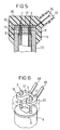
- a preferred further processing of the piezoelectric actuator is pleacken on the contact pins 3, a contact plate 10 which has two continuous contact holes 16 at a corresponding distance, in which the contact pins 3 are inserted, as shown in Figure 6.
- the contact plate 10 is preferably formed of an insulating plastic, wherein in the interior of the contact plate 10, starting from the contact holes 16 each have an electrical Line 17 is guided to a pin 18, which protrude from the contact plate 10.
- the piezoelectric actuator is inserted with the hollow profile 4 in a housing 13, wherein the housing 13 in a cover plate 19 electrically insulated bushings 14 for passing the contact pins 3, as shown in Figure 5.
- the housing 13 is made, for example, of metal, in particular steel or aluminum, or of a ceramic.
- the bushings 14 are formed insulated in an electrically conductive housing 13.
- the contact plate 10 is attached. Subsequently, the upper part of the housing 13, the contact pins 3 and the contact plate 10 are encapsulated with a connector housing 20.
- the connector housing 20 is formed such that the terminal pins 18 protrude into a terminal chamber 12 and thus are ready for a contact.
- Figure 5 thus shows a structural unit with a piezoelectric actuator 1, with housing 13 and a connector housing 20 which is pre-assembled and can be flanged with the terminal chamber 12 on a corresponding injector.
Landscapes
- Engineering & Computer Science (AREA)
- Chemical & Material Sciences (AREA)
- Combustion & Propulsion (AREA)
- Mechanical Engineering (AREA)
- General Engineering & Computer Science (AREA)
- General Electrical Machinery Utilizing Piezoelectricity, Electrostriction Or Magnetostriction (AREA)
- Fuel-Injection Apparatus (AREA)
Claims (7)
- Actionneur piézoélectrique (1) équipé de connexions électriques (3) servant à déterminer la longueur de l'actionneur (1),
dans lequel l'actionneur (1) est logé dans un profilé creux préfabriqué (4),
le profilé creux (4) étant rempli au moins partiellement d'une couche de passivation et
les connexions électriques (3) étant prolongées hors de la couche de passivation et du profilé creux (4), caractérisé- en ce que, comme connexions électriques, sont prévues des lamelles de contact (2),- en ce que le profilé creux présente un évidement central (5) et deux fentes (6) qui partent de l'évidement central (5),- en ce que l'actionneur (1) est disposé dans l'évidement central et les lamelles de contact (2) s'étendent dans les fentes (6). - Actionneur piézoélectrique selon la revendication 1, caractérisé en ce qu'au moins le côté supérieur de l'actionneur (1) s'étend au-delà du profilé creux (4) et en ce que la partie de l'actionneur (1) qui fait saillie hors du profilé creux (4) est entourée par coulée, au moins latéralement, avec une couche de passivation (8).
- Actionneur piézoélectrique selon la revendication 1, caractérisé en ce que les broches sont disposées à peu près parallèlement à la direction longitudinale de l'actionneur (1) et en ce que, sur un côté, les broches se prolongent au-delà de l'actionneur (1) dans la direction longitudinale.
- Actionneur piézoélectrique selon la revendication 3, caractérisé en ce que le profilé creux (5) présente deux évidements de broche (7) décalés latéralement par rapport à l'évidement central (5) et, qui sont reliés à l'évidement central (5) par des fentes (6).
- Actionneur piézoélectrique selon la revendication 4, caractérisé en ce qu'à la transition avec les évidements de broche (7), les fentes (6) présentent une plus petite largeur que les broches (3) afin qu'elles soient immobilisées dans les évidements de broche (7) et qu'elles présentent ainsi un écartement mutuel défini.
- Actionneur piézoélectrique selon la revendication 1, caractérisé en ce que le profilé creux (4) est emboîté au moins partiellement dans un boîtier (13), en ce que les broches (3) s'étendent à travers le boîtier (13) en s'engageant dans un boîtier de fiche (11) moulé par injection sur le boîtier (13), et en ce que les broches (3) munies d'une plaque de contact (10) sont connectées à des lamelles de fiche (18) qui font saillie dans une chambre de connexion (12).
- Actionneur piézoélectrique selon une des revendications 4 à 6, caractérisé en ce que les broches (3) sont connectées à l'actionneur (1) par l'intermédiaire de lamelles (2) et en ce que les fentes (6) sont formées selon un trajet courbe, vu perpendiculairement à la direction longitudinale de l'actionneur (1), dans lequel les lamelles s'étendent.
Applications Claiming Priority (3)
| Application Number | Priority Date | Filing Date | Title |
|---|---|---|---|
| DE19715487A DE19715487C2 (de) | 1997-04-14 | 1997-04-14 | Piezoelektrischer Aktor mit einem Hohlprofil |
| DE19715487 | 1997-04-14 | ||
| PCT/DE1998/001021 WO1998047188A2 (fr) | 1997-04-14 | 1998-04-08 | Actionneur piezoelectrique comportant un profile creux |
Publications (2)
| Publication Number | Publication Date |
|---|---|
| EP0976166A2 EP0976166A2 (fr) | 2000-02-02 |
| EP0976166B1 true EP0976166B1 (fr) | 2007-12-19 |
Family
ID=7826437
Family Applications (1)
| Application Number | Title | Priority Date | Filing Date |
|---|---|---|---|
| EP98930643A Expired - Lifetime EP0976166B1 (fr) | 1997-04-14 | 1998-04-08 | Actionneur piezoelectrique comportant un profile creux |
Country Status (3)
| Country | Link |
|---|---|
| EP (1) | EP0976166B1 (fr) |
| DE (2) | DE19715487C2 (fr) |
| WO (1) | WO1998047188A2 (fr) |
Families Citing this family (45)
| Publication number | Priority date | Publication date | Assignee | Title |
|---|---|---|---|---|
| DE19818068A1 (de) | 1998-04-22 | 1999-10-28 | Siemens Ag | Piezoelektronischer Aktor für einen Stellantrieb |
| DE19860001C2 (de) | 1998-12-23 | 2001-10-04 | Epcos Ag | Piezoelektrisches Bauelement, Verfahren zu dessen Herstellung und Verwendung eines derartigen Bauelements |
| DE19905413A1 (de) * | 1999-02-10 | 2000-08-24 | Bosch Gmbh Robert | Injektor mit Piezo-Mehrlagenaktor für Einspritzsysteme |
| DE19909450A1 (de) * | 1999-03-04 | 2000-09-07 | Bosch Gmbh Robert | Piezoelektrischer Aktor |
| DE19910111B4 (de) * | 1999-03-08 | 2007-06-06 | Siemens Ag | Verfahren zur Herstellung eines elektrotechnischen Bauteils mit einer kunststoffpassivierten Oberfläche und Vorrichtung zum Durchführen des Verfahrens |
| DE19914411A1 (de) * | 1999-03-30 | 2000-10-12 | Bosch Gmbh Robert | Piezoelektrischer Aktor |
| DE19928185B4 (de) * | 1999-06-19 | 2006-05-24 | Robert Bosch Gmbh | Piezoaktor |
| GB9919661D0 (en) * | 1999-08-20 | 1999-10-20 | Lucas Industries Ltd | Actuator housing |
| DE19940346B4 (de) * | 1999-08-25 | 2018-03-22 | Continental Automotive Gmbh | Piezoaktor mit einer Anschlußvorrichtung |
| DE19946965B4 (de) * | 1999-09-30 | 2006-06-01 | Siemens Ag | Geräuschgedämpfte Aktoreinheit mit einem Piezoelement |
| DE19947071B4 (de) * | 1999-09-30 | 2006-07-27 | Siemens Ag | Geräuschgedämpfte Aktoreinheit |
| US20010033125A1 (en) * | 2000-04-20 | 2001-10-25 | Tokin Corporation | Multilayer piezoelectric actuator device having a conductive member attached to an external electrode thereof |
| DE10039218A1 (de) * | 2000-08-11 | 2002-02-28 | Bosch Gmbh Robert | Piezoelektrische Aktuatoranordnung, inbesondere zur Betätigung eines Ventils in einem Kraftfahrzeug |
| DE10131621A1 (de) * | 2001-06-29 | 2003-01-23 | Epcos Ag | Weiterkontaktierung für ein elektrisches Bauteil sowie piezoelektrisches Bauteil in Vielschichtbauweise |
| DE10144919A1 (de) * | 2001-09-12 | 2003-05-22 | Siemens Ag | Vorrichtung umfassend einen piezoelektrischen Aktor |
| DE10205909B4 (de) | 2002-02-13 | 2005-11-10 | Siemens Ag | Dichtungselement für den Piezoaktor eines Kraftstoff-Einspritzventils |
| DE10229494A1 (de) * | 2002-07-01 | 2004-01-29 | Siemens Ag | Piezoaktor sowie Verfahren zu dessen Herstellung |
| DE10253956A1 (de) * | 2002-11-19 | 2004-06-24 | Siemens Ag | Piezoaktorkontaktierung für Einspritzventil und Verfahren zu dessen Herstellung |
| EP1445470A1 (fr) | 2003-01-24 | 2004-08-11 | Siemens VDO Automotive S.p.A. | Dispositif de dosage avec conecteur électrique |
| DE10347768B4 (de) | 2003-10-14 | 2006-03-09 | Siemens Ag | Aufnahmehülse für einen Piezoaktor |
| WO2005035971A1 (fr) * | 2003-10-14 | 2005-04-21 | Siemens Aktiengesellschaft | Actionneur piezoelectrique et procede de production associe |
| DE102004011697A1 (de) * | 2004-03-10 | 2005-11-24 | Siemens Ag | Verfahren zur Anordnung eines Kontaktpins für ein Piezoelement sowie Hülse und Aktoreinheit |
| DE102004012926A1 (de) * | 2004-03-17 | 2005-10-06 | Robert Bosch Gmbh | Aktormodul |
| DE102004018224A1 (de) * | 2004-04-15 | 2005-11-03 | Robert Bosch Gmbh | Vorrichtung mit piezoelektrischem Aktor |
| DE102004024123A1 (de) * | 2004-05-14 | 2005-12-08 | Siemens Ag | Kopfplattenbaugruppe für einen Aktor und Herstellungsverfahren für einen Aktor |
| DE102004028884A1 (de) * | 2004-06-15 | 2006-01-05 | Robert Bosch Gmbh | Piezoaktor |
| US6994559B1 (en) | 2004-08-20 | 2006-02-07 | Siemens Aktiengesellschaft | Device for the electrical connection of contact pins to connecting pins of a plug-in connector formed from the device |
| EP1628371B1 (fr) * | 2004-08-20 | 2012-11-14 | Continental Automotive GmbH | Dispositif de connection électrique |
| EP1628370B1 (fr) * | 2004-08-20 | 2012-11-07 | Continental Automotive GmbH | Dispositif de connection électrique |
| DE102004053491B3 (de) | 2004-11-05 | 2005-12-29 | Siemens Ag | Vorrichtung zur elektrischen Verbindung von Kontaktstiften mit Anschlussstiften eines von der Vorrichtung ausgebildeten Steckverbinders |
| DE102004058019A1 (de) * | 2004-12-01 | 2006-06-08 | Siemens Ag | Kraftstoffinjektor für eine Brennkraftmaschine |
| WO2006058901A1 (fr) * | 2004-12-01 | 2006-06-08 | Siemens Aktiengesellschaft | Injecteur de carburant pour moteur a combustion interne |
| DE102004058643B4 (de) * | 2004-12-02 | 2009-01-08 | Continental Automotive Gmbh | Kraftstoffinjektor für eine Brennkraftmaschine |
| DE102004063293B4 (de) * | 2004-12-29 | 2010-07-08 | Continental Automotive Gmbh | Kraftstoffinjektor für eine Brennkraftmaschine |
| DE102005013284B4 (de) * | 2005-03-22 | 2007-02-15 | Siemens Ag | Elektrische Verbindungsvorrichtung, insbesondere für den elektrischen Aktor eines Kraftstoffinjektors |
| DE102005014766A1 (de) * | 2005-03-31 | 2006-09-21 | Siemens Ag | Piezoelektrischer Aktor |
| DE102005024196B4 (de) * | 2005-05-25 | 2013-05-23 | Continental Automotive Gmbh | Kraftstoffinjektor für eine Brennkraftmaschine sowie Verfahren zur Montage eines derartigen Kraftstoffinjektors |
| DE102005039558B4 (de) * | 2005-08-22 | 2015-10-15 | Robert Bosch Gmbh | Anordnung mit einem Piezoaktor und ein Verfahren zu dessen Herstellung |
| DE102005043622A1 (de) * | 2005-09-13 | 2007-03-22 | Siemens Ag | Piezoelektrische Aktoreinheit bzw. piezoelektrische Antriebsvorrichtung |
| DE102006026933A1 (de) * | 2006-06-09 | 2007-12-13 | Siemens Ag | Piezoaktuator |
| DE102008003821A1 (de) * | 2008-01-10 | 2009-07-16 | Epcos Ag | Piezoelektrische Aktoreinheit |
| DE102009034099A1 (de) * | 2009-07-21 | 2011-01-27 | Epcos Ag | Piezoaktor mit elektrischer Kontaktierung |
| DE102010050266A1 (de) | 2010-11-02 | 2012-05-03 | Epcos Ag | Aktoreinheit, Verfahren zur Fertigung einer Aktoreinheit und Hülse zur Aufnahme eines Piezoaktors |
| DE102010050265A1 (de) * | 2010-11-02 | 2012-05-03 | Epcos Ag | Verfahren zur Herstellung einer Aktoreinheit sowie Hülse zur Aufnahme eines Piezoaktors |
| DE102016112101B4 (de) * | 2016-07-01 | 2018-08-02 | Physik Instrumente (Pi) Gmbh & Co. Kg | Vorrichtung umfassend einen Ultraschallaktor und eine Halterungsvorrichtung, wobei der Ultraschallaktor an der Halterungsvorrichtung angeordnet ist |
Family Cites Families (8)
| Publication number | Priority date | Publication date | Assignee | Title |
|---|---|---|---|---|
| JPS63260087A (ja) * | 1986-12-26 | 1988-10-27 | Olympus Optical Co Ltd | 積層型圧電アクチュエータ |
| DE3850641T2 (de) * | 1987-12-02 | 1994-10-27 | Nippon Electric Co | Struktur zur Versiegelung eines elektrostriktiven Elements. |
| DE3833109A1 (de) * | 1988-09-29 | 1990-04-05 | Siemens Ag | Piezoelektrisches stellglied |
| DE3927406A1 (de) * | 1989-08-19 | 1991-02-21 | Hoechst Ceram Tec Ag | Piezokeramischer transformator |
| US5148077A (en) * | 1990-09-28 | 1992-09-15 | Caterpillar Inc. | Coating surrounding a piezoelectric solid state motor stack |
| DE4201937C2 (de) * | 1991-01-25 | 1997-05-22 | Murata Manufacturing Co | Piezoelektrisches laminiertes Stellglied |
| US5168189A (en) * | 1991-09-18 | 1992-12-01 | Caterpillar Inc. | Solderless connector for a solid state motor stack |
| US5218259A (en) * | 1992-02-18 | 1993-06-08 | Caterpillar Inc. | Coating surrounding a piezoelectric solid state motor stack |
-
1997
- 1997-04-14 DE DE19715487A patent/DE19715487C2/de not_active Expired - Lifetime
-
1998
- 1998-04-08 EP EP98930643A patent/EP0976166B1/fr not_active Expired - Lifetime
- 1998-04-08 WO PCT/DE1998/001021 patent/WO1998047188A2/fr not_active Ceased
- 1998-04-08 DE DE59814146T patent/DE59814146D1/de not_active Expired - Lifetime
Also Published As
| Publication number | Publication date |
|---|---|
| WO1998047188A3 (fr) | 1999-01-28 |
| WO1998047188A2 (fr) | 1998-10-22 |
| EP0976166A2 (fr) | 2000-02-02 |
| DE19715487A1 (de) | 1998-10-22 |
| DE59814146D1 (de) | 2008-01-31 |
| DE19715487C2 (de) | 2002-06-13 |
Similar Documents
| Publication | Publication Date | Title |
|---|---|---|
| EP0976166B1 (fr) | Actionneur piezoelectrique comportant un profile creux | |
| EP3863373B1 (fr) | Dispositif de chauffage électrique et son procédé de fabrication | |
| EP0976165B1 (fr) | Actionneur piezoelectrique a nouveau mode de contact et son procede de fabrication | |
| DE68928095T2 (de) | Verfahren zur Herstellung eines elektronischen Moduls und elektronisches Modul, hergestellt nach diesem Verfahren | |
| EP1230688A1 (fr) | Actionneur piezo | |
| WO2008049619A1 (fr) | Élément producteur de chaleur pour un dispositif de chauffage électrique, et son procédé de fabrication | |
| DE10115601C1 (de) | Trommelkommutator sowie Verfahren zu seiner Herstellung | |
| DE19956844A1 (de) | Plankommutator, Verfahren zu seiner Herstellung sowie Leiterrohling und Kohlenstoffscheibe zur Verwendung bei seiner Herstellung | |
| EP1673533B1 (fr) | Actionneur piezoelectrique et procede de production associe | |
| EP0913882A2 (fr) | Méthode pour isoler un dispositif électrique | |
| EP1699113A2 (fr) | Connecteur électrique | |
| EP0938753B1 (fr) | Actionneur piezoelectrique pourvu d'une connexion electrique | |
| DE102020113402A1 (de) | Elektrische Heizvorrichtung | |
| WO2002089226A2 (fr) | Systeme de contact supplementaire pour composant electrique et composant piezo-electrique a structure multicouche | |
| EP1467597B1 (fr) | Dispositif de chauffage | |
| DE102019211565A1 (de) | Elektrische Heizvorrichtung und Verfahren zu deren Herstellung | |
| EP2396535B1 (fr) | Actionneur piezoelectrique, procede de production de l'actionneur et injecteur | |
| EP0995135A2 (fr) | Dispositif transpondeur et son procede de production | |
| EP1587152B1 (fr) | Dispositif avec actionneur piézoélectrique | |
| DE102008012781B4 (de) | Elektromagnetisches Ventil | |
| DE10259320A1 (de) | Druckkontaktiertes elektrisches Bauelement | |
| EP4354663B1 (fr) | Connecteur a sertir pour la connexion mecanique et electriquement conductrice d'un contact de connexion electrique a un conducteur electrique et connexion a sertir d'un contact de connexion electrique a un conducteur electrique | |
| DE19845597C1 (de) | Vorrichtung zum Einpressen eines Rohrheizkörpers in eine Aufnahmenut eines Heißkanalblocks eines Kunststoffspritzgießwerkzeugs o. dgl. | |
| EP1508941B1 (fr) | Connecteur électrique avec réservoir de brasure dans une région de contact | |
| EP1798782B1 (fr) | Actionneur piézo-électrique et méthode de fabrication d'un empilement piézo-électrique |
Legal Events
| Date | Code | Title | Description |
|---|---|---|---|
| PUAI | Public reference made under article 153(3) epc to a published international application that has entered the european phase |
Free format text: ORIGINAL CODE: 0009012 |
|
| 17P | Request for examination filed |
Effective date: 19991005 |
|
| AK | Designated contracting states |
Kind code of ref document: A2 Designated state(s): DE FR GB IT |
|
| 17Q | First examination report despatched |
Effective date: 20040924 |
|
| GRAP | Despatch of communication of intention to grant a patent |
Free format text: ORIGINAL CODE: EPIDOSNIGR1 |
|
| GRAS | Grant fee paid |
Free format text: ORIGINAL CODE: EPIDOSNIGR3 |
|
| GRAA | (expected) grant |
Free format text: ORIGINAL CODE: 0009210 |
|
| RAP1 | Party data changed (applicant data changed or rights of an application transferred) |
Owner name: SIEMENS VDO AUTOMOTIVE AG |
|
| AK | Designated contracting states |
Kind code of ref document: B1 Designated state(s): DE FR GB IT |
|
| REG | Reference to a national code |
Ref country code: GB Ref legal event code: FG4D Free format text: NOT ENGLISH |
|
| REF | Corresponds to: |
Ref document number: 59814146 Country of ref document: DE Date of ref document: 20080131 Kind code of ref document: P |
|
| RAP2 | Party data changed (patent owner data changed or rights of a patent transferred) |
Owner name: VDO AUTOMOTIVE AG |
|
| ET | Fr: translation filed | ||
| GBV | Gb: ep patent (uk) treated as always having been void in accordance with gb section 77(7)/1977 [no translation filed] | ||
| RAP2 | Party data changed (patent owner data changed or rights of a patent transferred) |
Owner name: CONTINENTAL AUTOMOTIVE GMBH |
|
| PLBE | No opposition filed within time limit |
Free format text: ORIGINAL CODE: 0009261 |
|
| STAA | Information on the status of an ep patent application or granted ep patent |
Free format text: STATUS: NO OPPOSITION FILED WITHIN TIME LIMIT |
|
| 26N | No opposition filed |
Effective date: 20080922 |
|
| PG25 | Lapsed in a contracting state [announced via postgrant information from national office to epo] |
Ref country code: GB Free format text: LAPSE BECAUSE OF FAILURE TO SUBMIT A TRANSLATION OF THE DESCRIPTION OR TO PAY THE FEE WITHIN THE PRESCRIBED TIME-LIMIT Effective date: 20071219 |
|
| PG25 | Lapsed in a contracting state [announced via postgrant information from national office to epo] |
Ref country code: IT Free format text: LAPSE BECAUSE OF NON-PAYMENT OF DUE FEES Effective date: 20080430 |
|
| REG | Reference to a national code |
Ref country code: FR Ref legal event code: PLFP Year of fee payment: 19 |
|
| REG | Reference to a national code |
Ref country code: FR Ref legal event code: PLFP Year of fee payment: 20 |
|
| PGFP | Annual fee paid to national office [announced via postgrant information from national office to epo] |
Ref country code: FR Payment date: 20170419 Year of fee payment: 20 Ref country code: DE Payment date: 20170430 Year of fee payment: 20 |
|
| REG | Reference to a national code |
Ref country code: DE Ref legal event code: R071 Ref document number: 59814146 Country of ref document: DE |