EP0975477B1 - Insert de securite generant un signal vibratoire transversal et dispositif de detection de la mise en appui d'un pneumatique sur un insert - Google Patents
Insert de securite generant un signal vibratoire transversal et dispositif de detection de la mise en appui d'un pneumatique sur un insert Download PDFInfo
- Publication number
- EP0975477B1 EP0975477B1 EP98928201A EP98928201A EP0975477B1 EP 0975477 B1 EP0975477 B1 EP 0975477B1 EP 98928201 A EP98928201 A EP 98928201A EP 98928201 A EP98928201 A EP 98928201A EP 0975477 B1 EP0975477 B1 EP 0975477B1
- Authority
- EP
- European Patent Office
- Prior art keywords
- vehicle
- insert
- tyre
- safety insert
- signals
- Prior art date
- Legal status (The legal status is an assumption and is not a legal conclusion. Google has not performed a legal analysis and makes no representation as to the accuracy of the status listed.)
- Expired - Lifetime
Links
- 238000001514 detection method Methods 0.000 claims description 17
- 238000005096 rolling process Methods 0.000 claims description 13
- 230000005540 biological transmission Effects 0.000 claims description 3
- 230000000712 assembly Effects 0.000 claims 1
- 238000000429 assembly Methods 0.000 claims 1
- 238000001228 spectrum Methods 0.000 description 6
- 230000001133 acceleration Effects 0.000 description 5
- 230000000284 resting effect Effects 0.000 description 4
- 239000000725 suspension Substances 0.000 description 4
- DOSMHBDKKKMIEF-UHFFFAOYSA-N 2-[3-(diethylamino)-6-diethylazaniumylidenexanthen-9-yl]-5-[3-[3-[4-(1-methylindol-3-yl)-2,5-dioxopyrrol-3-yl]indol-1-yl]propylsulfamoyl]benzenesulfonate Chemical compound C1=CC(=[N+](CC)CC)C=C2OC3=CC(N(CC)CC)=CC=C3C(C=3C(=CC(=CC=3)S(=O)(=O)NCCCN3C4=CC=CC=C4C(C=4C(NC(=O)C=4C=4C5=CC=CC=C5N(C)C=4)=O)=C3)S([O-])(=O)=O)=C21 DOSMHBDKKKMIEF-UHFFFAOYSA-N 0.000 description 3
- 239000000463 material Substances 0.000 description 3
- 238000005259 measurement Methods 0.000 description 3
- 239000002689 soil Substances 0.000 description 3
- 230000007423 decrease Effects 0.000 description 2
- 238000001914 filtration Methods 0.000 description 2
- 238000010438 heat treatment Methods 0.000 description 2
- 230000035945 sensitivity Effects 0.000 description 2
- 230000006835 compression Effects 0.000 description 1
- 238000007906 compression Methods 0.000 description 1
- 230000008878 coupling Effects 0.000 description 1
- 238000010168 coupling process Methods 0.000 description 1
- 238000005859 coupling reaction Methods 0.000 description 1
- 230000003247 decreasing effect Effects 0.000 description 1
- 230000000593 degrading effect Effects 0.000 description 1
- 230000006866 deterioration Effects 0.000 description 1
- 238000010586 diagram Methods 0.000 description 1
- 230000009365 direct transmission Effects 0.000 description 1
- 230000005284 excitation Effects 0.000 description 1
- 230000007274 generation of a signal involved in cell-cell signaling Effects 0.000 description 1
- 239000000314 lubricant Substances 0.000 description 1
- 238000006386 neutralization reaction Methods 0.000 description 1
- 230000010355 oscillation Effects 0.000 description 1
- 230000003595 spectral effect Effects 0.000 description 1
- 230000001960 triggered effect Effects 0.000 description 1
- XLYOFNOQVPJJNP-UHFFFAOYSA-N water Substances O XLYOFNOQVPJJNP-UHFFFAOYSA-N 0.000 description 1
Images

Classifications
-
- B—PERFORMING OPERATIONS; TRANSPORTING
- B60—VEHICLES IN GENERAL
- B60C—VEHICLE TYRES; TYRE INFLATION; TYRE CHANGING; CONNECTING VALVES TO INFLATABLE ELASTIC BODIES IN GENERAL; DEVICES OR ARRANGEMENTS RELATED TO TYRES
- B60C23/00—Devices for measuring, signalling, controlling, or distributing tyre pressure or temperature, specially adapted for mounting on vehicles; Arrangement of tyre inflating devices on vehicles, e.g. of pumps or of tanks; Tyre cooling arrangements
- B60C23/02—Signalling devices actuated by tyre pressure
- B60C23/04—Signalling devices actuated by tyre pressure mounted on the wheel or tyre
- B60C23/0408—Signalling devices actuated by tyre pressure mounted on the wheel or tyre transmitting the signals by non-mechanical means from the wheel or tyre to a vehicle body mounted receiver
- B60C23/0422—Signalling devices actuated by tyre pressure mounted on the wheel or tyre transmitting the signals by non-mechanical means from the wheel or tyre to a vehicle body mounted receiver characterised by the type of signal transmission means
- B60C23/0469—Transmission by sound, e.g. ultra-sound
-
- B—PERFORMING OPERATIONS; TRANSPORTING
- B60—VEHICLES IN GENERAL
- B60C—VEHICLE TYRES; TYRE INFLATION; TYRE CHANGING; CONNECTING VALVES TO INFLATABLE ELASTIC BODIES IN GENERAL; DEVICES OR ARRANGEMENTS RELATED TO TYRES
- B60C17/00—Tyres characterised by means enabling restricted operation in damaged or deflated condition; Accessories therefor
- B60C17/04—Tyres characterised by means enabling restricted operation in damaged or deflated condition; Accessories therefor utilising additional non-inflatable supports which become load-supporting in emergency
- B60C17/06—Tyres characterised by means enabling restricted operation in damaged or deflated condition; Accessories therefor utilising additional non-inflatable supports which become load-supporting in emergency resilient
-
- B—PERFORMING OPERATIONS; TRANSPORTING
- B60—VEHICLES IN GENERAL
- B60C—VEHICLE TYRES; TYRE INFLATION; TYRE CHANGING; CONNECTING VALVES TO INFLATABLE ELASTIC BODIES IN GENERAL; DEVICES OR ARRANGEMENTS RELATED TO TYRES
- B60C23/00—Devices for measuring, signalling, controlling, or distributing tyre pressure or temperature, specially adapted for mounting on vehicles; Arrangement of tyre inflating devices on vehicles, e.g. of pumps or of tanks; Tyre cooling arrangements
- B60C23/06—Signalling devices actuated by deformation of the tyre, e.g. tyre mounted deformation sensors or indirect determination of tyre deformation based on wheel speed, wheel-centre to ground distance or inclination of wheel axle
- B60C23/063—Generating directly an audible signal by deformation of the tyre
-
- B—PERFORMING OPERATIONS; TRANSPORTING
- B60—VEHICLES IN GENERAL
- B60C—VEHICLE TYRES; TYRE INFLATION; TYRE CHANGING; CONNECTING VALVES TO INFLATABLE ELASTIC BODIES IN GENERAL; DEVICES OR ARRANGEMENTS RELATED TO TYRES
- B60C19/00—Tyre parts or constructions not otherwise provided for
- B60C2019/006—Warning devices, e.g. devices generating noise due to flat or worn tyres
-
- Y—GENERAL TAGGING OF NEW TECHNOLOGICAL DEVELOPMENTS; GENERAL TAGGING OF CROSS-SECTIONAL TECHNOLOGIES SPANNING OVER SEVERAL SECTIONS OF THE IPC; TECHNICAL SUBJECTS COVERED BY FORMER USPC CROSS-REFERENCE ART COLLECTIONS [XRACs] AND DIGESTS
- Y10—TECHNICAL SUBJECTS COVERED BY FORMER USPC
- Y10T—TECHNICAL SUBJECTS COVERED BY FORMER US CLASSIFICATION
- Y10T152/00—Resilient tires and wheels
- Y10T152/10—Tires, resilient
- Y10T152/10009—Emergency
-
- Y—GENERAL TAGGING OF NEW TECHNOLOGICAL DEVELOPMENTS; GENERAL TAGGING OF CROSS-SECTIONAL TECHNOLOGIES SPANNING OVER SEVERAL SECTIONS OF THE IPC; TECHNICAL SUBJECTS COVERED BY FORMER USPC CROSS-REFERENCE ART COLLECTIONS [XRACs] AND DIGESTS
- Y10—TECHNICAL SUBJECTS COVERED BY FORMER USPC
- Y10T—TECHNICAL SUBJECTS COVERED BY FORMER US CLASSIFICATION
- Y10T152/00—Resilient tires and wheels
- Y10T152/10—Tires, resilient
- Y10T152/10027—Tires, resilient with wear indicating feature
Definitions
- the invention relates to a safety insert intended to be mounted in an assembly comprising a tire and a rim of a vehicle.
- the support of the tire on the safety insert is accompanied by a deterioration more or less marked performance that may not be perceptible by the driver through the behavior and comfort of the vehicle.
- the service life in operation of these inserts is limited. It is therefore essential for his security that the driver is warned as soon as a tire is resting on its safety insert, for that he can comply with the instructions of their manufacturer.
- US Pat. No. 4,262,724 proposes in particular a safety insert intended to be mounted in an assembly comprising a tire and a rim and radially outwardly relative to the rim.
- This insert has a radially outer surface which defines a radial support for the crown of the tire when the tire is deflated as well than means for generating vibratory warning signals during a taxi ride. support.
- These means can be a variation of the rolling radius under the support of the insert between a minimum radius and a maximum radius to create a vibration in rolling or one or more bumps. All vibratory warning signals generated by these means are oriented in the plane of the tire and rim assembly and more precisely in a substantially vertical direction.
- the patent application WO 94/03338 proposes a device for detecting the placing a tire in abutment on a safety insert.
- This device includes a accelerometer per wheel, placed on one of the suspension elements of the wheel and measuring vertical accelerations.
- the accelerometers are connected to a central unit of treatment. The analysis is based on the detection of the appearance during the setting in support a resonant mode characteristic of the rolling support.
- EP 0 363 369 discloses a safety insert corresponding to the preambles of claims 1 and 2.
- the invention aims at a safety insert which warns the driver, directly or no, since the support of the tire in a very wide range of speeds of the vehicle while maintaining a tolerable character both for the driver and the mechanical, in the range of authorized speeds.
- the subject of the invention is also a device for detecting the setting in support of a pneumatic on its safety insert can inter alia cooperate with the insert of security according to the invention.
- vehicle means an autonomous rolling unit, vehicle of tourism, tractor or trailer truck, caravan, motorcycle ...
- a “rib” is an element located on the radially outer surface of an insert safety device, of elongated shape, with a substantially circumferential orientation and whose radial height is less than or equal to the axial width; the ribs are "straight" when their axial section is rectangular and “inclined” when their axial section has the form of a parallelogram.
- a “slat” is a similar element whose radial height is greater than the axial width.
- Safety inserts according to the invention are defined by the characteristics claims 1 and 2, and a device for detecting the implementation of support of a tire of a vehicle on one of such inserts is defined by claim 9.
- the support surface of the insert has a transverse position variation as a function of its azimuth.
- the support surface of the insert has ribs straight whose circumferential orientation varies according to their azimuth.
- the bearing surface of the insert has elements generating during radial compression a transverse force.
- This embodiment is particularly flexible. We can indeed use ribs or slats inclined relative to a longitudinal plane in a variable manner in according to their azimuth.
- the safety insert according to the invention has a surface with at least two axially adjacent zones, the zone intended to be arranged to the outside of the vehicle not having means for generating signals oriented parallel to the axis of rotation of the tire and rim assembly.
- the safety insert according to the invention comprises a bearing surface with a active signal generation zone such that said signals have a maximum preceded and followed by a minimum of opposite meaning.
- the active zone is advantageously between 1/4 and 1/2 of the circumference of said insert and the absolute value of the minimums of the generated signal is between 1/4 and 3/4 of the absolute value of the maximum.
- Such generated signals have the advantage of giving a spectrum of vibrations transmitted to the chassis of the vehicle while driving in a good frequency band delimited which promotes accurate and reliable detection.
- the above-mentioned device has the particularity, with regard to the known devices, of carrying out a vibration analysis of the vehicle chassis instead of the suspension members.
- this device can preferentially use the direct transmission of vibration between the wheels and the chassis, in addition to vertical directions. As a result, this device can be much more selective and sensitive that existing devices and have only one sensor rigidly connected to one chassis parts.
- the device according to the invention is particularly well suited to the detection of the setting in support of a tire on a safety insert according to the invention, but, it can also be used with any other insert, with or without means of alert vibratory of the setting in support. In this case, it may be necessary to use two sensors measuring accelerations or more, instead of just one. Each sensor is then, preferably, connected to one of the axles of the vehicle.
- the chassis vibration processing means calculate a first magnitude characteristic in at least one given frequency band, calculate a criterion C corresponding to a given combination of the first magnitude (s) characteristics, compare this criterion C to a given threshold and trigger a alarm when the result of the comparison obeys a given relation.
- the means of treatment calculate a first characteristic quantity in at least a first band of the axle-specific frequencies of the vehicle and calculate a criterion C corresponding to a weighted value of these first characteristic quantities.
- the means for processing the vibrations of the chassis can also calculate, in addition, a second characteristic quantity in a given second frequency band such that in said second band, said vibrations are substantially independent of the setting in support of the tire on its safety insert and deduce a criterion C corresponding to a value normalized by this second characteristic quantity of first characteristic quantities, weighted or not.
- the processing means determine in addition the frequency of rotation of the tire and said first band or bands of frequencies are narrow frequency bands each centered on a frequency multiple of said rotation frequency of the tire.
- these first frequency bands are between 10 and 200 Hz.
- the processing centered on the multiple frequencies of the rotation frequency of the pneumatic improves very substantially the sensitivity of the detection of the support.
- the calculated characteristic quantity may be the RMS value of the signals.
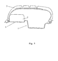
- FIG. 1 shows a wheel rim 1 equipped with an annular safety insert 2 resting on the scope 6 of the rim 1.
- the particular geometry of this wheel rim 1 is particularly described in French Patent Application No. 2,713,558. seats of different diameters and is particularly suitable for in easy place of this safety insert 2.
- This set allows rolling despite a significant pressure drop in the tire 3.
- the inside of the deformed tire rubs on the outer surface of the insert causing a heating up which limits the available range: it is important that the driver be informed as soon as a tire is supported on its insert 2.
- a safety insert comprising means for generating vibratory warning signals transverse.
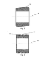
- FIG. 2 A first embodiment of such an insert is shown in Figure 2.
- This insert 9 has a bearing surface 10 which shifts axially according to its azimuth. In Consequently, when rolling in support of this surface 10 against that of the top of the Pneumatic, the entire tire rim and insert will produce at each wheel turn a lateral thrust oscillation that the driver or a sensing device is going to easily feel.
- Figure 3 shows another embodiment.
- the bearing surface 13 of this insert 12 has slats 14 inclined relative to a transverse plane of the insert and whose the inclination is variable according to their azimuth.
- the inclination of these slats is diametrically opposite and the evolution of the inclination is substantially sinusoidal.
- ribs or preferably relatively wide ribs arranged adjacent to lamellae of similar or greater radial height it is advantageous to design the rigidity and geometry of these ribs and lamellae so that the rolling radius of the insert remains constant when driving under support.
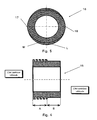
- FIG. 4 shows a safety insert 15 comprising two adjacent zones A and B. axially.
- Zone B disposed on the side intended to be placed towards the outside of the vehicle does not include means for generating signals oriented parallel to the axis of rotation of the tire and rim assembly.
- This zone is thus inactive whereas the A zone disposed towards the interior of the vehicle comprises inclined slats for generate transverse vibratory signals.
- This insert 15 makes it possible to preserve a excellent cornering behavior because then it is the substantially cylindrical zone B which supports most of the load from the top of the tire in because of the angle of camber against important taken by it. In a straight line, the The operation of the insert 15 is similar to that of FIGS. 2 and 3.
- Such an insert may also advantageously have a slightly conical zone B with its minimum diameter of the outer side of the insert to fit the counter angle camber caught by the tire and the wheel turning.
- FIG. 5 shows an insert 16 comprising in addition slats of variable inclination in azimuth function, two radial bosses 17 and 18 created by giving the slats a variable height depending on the azimuth that will cause vibrational excitation vertical.
- the circle L corresponds to the outside of the bearing surface of the insert and the oval M corresponds to the envelope of the bottom of the slats.
- Slats in the example presented have a zero thickness at the two peaks of the bosses 17 and 18.
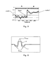
- FIG. 6a shows a preferred form of signal generated by a security insert according to the invention.
- This signal differs from zero only in a zone limited to approximately 1/3 of the circumference of the insert. It includes a first minimum F Ymin followed by a maximum F Ymax of opposite direction and finally followed by a second minimum.
- the two minima can have the same amplitude between 1/5 and 1/2 of F Ymax .
- the safety inserts described above can very easily generate signals similar to those in Figure 6. It is sufficient that the means used to generate the signals in Y vary in a similar way.
- the lateral position of the surface support 10 can follow an evolution corresponding to that of Figure 6a or 6b.
- a variation similar to that of FIG. generated signal evolution close to the shape of the curve 6a.
- insert 12 of FIG. 3 it is the orientation of the ribs or lamellae that must follow a evolution corresponding to the curves 6a or 6b.
- the safety inserts according to the invention can generate intensity signals large enough to be perceived by the driver of a vehicle. However, can also, to preserve the comfort of the passengers of the vehicle, use these inserts with a detecting device of the support which will now be described.
- FIG. 7 schematically shows a detection device according to the invention intended to be used with a two-axle passenger vehicle, for example a Renault Twingo.
- This device 20 comprises a sensor 21; a series of bandpass filters 22, 23, 24; three extractors 25, 26, 27 analog of the RMS value of the signals; a microcontroller 28 and a display 29.
- the assembly is placed in a single housing intended to be rigidly connected to one of the vehicle chassis parts.
- the sensor 21 is preferably a unidirectional accelerometer arranged in the vehicle so that that it measures accelerations in a plane comprising the longitudinal axes and transversal of the vehicle.
- the signals are then filtered by a series of bandpass filters arranged in parallel.
- the filter 22 eliminates the signals outside a band A adapted to the rear axle of the vehicle, of the order of 20 to 50 Hz.
- the filter 23 eliminates the signals outside a band B adapted to the front axle of the vehicle, of the order of 50 to 80 Hz and the filter 24 passes the signals included in a band E in which the signals are substantially independent of the support of a tire on its safety insert, of the order of 100 to 200 Hz or preferably 100 to 160 Hz.
- These three frequency bands may vary in particular depending on the type of safety insert used as well as depending on the chosen vehicle.
- the extractors 25, 26 and 27 extract the RMS values of the transmitted signals respectively by the bandpass filters 22, 23 and 24.
- the microcontroller 28 digitizes the signals in the analog-to-digital converter (A / D) 30.
- Element 31 of the microcontroller 28 calculates a criterion C, it can in particular perform a sum weighted RMS values of the A and B band signals and normalize this sum by the RMS value of the E-band signals.
- the vibratory energy included in the E band is a function of the type of soil on which the vehicle rolls.
- the normation obtained substantially improves the sensitivity of the device of detection by reducing the number of false alarms.
- This band E can also be located in a very low frequency band of the order of 3 to 7 Hz for example.
- the criterion C is then compared to a programmable threshold 33 in the comparator 32 and an alarm is triggered by the display 29 when C is greater than this threshold.
- Figure 9 shows the evolution of criterion C when the four tires of the Renault Twingo are correctly inflated (zone A) and when one of these tires is deflated which causes the setting of a support of this tire on its safety insert (zone B).
- Curves 1 show the gross evolution of C
- curves 2 show the result after the comparison with the threshold. This result is zero when C is below the threshold and is 1 when C is greater than the threshold.
- the display transmits an alarm to the driver when the result of the comparison is 1. This display can also be completed with a buzzer.
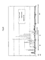
- FIG. 8 shows an example of the spectrum of the vibrations measured by the sensor 21 during driving with the Renault Twingo.
- a first curve corresponds to the case where four tires are properly inflated. There is usually a peak at low frequencies, around 9 Hz; this peak corresponds to the first harmonic of the turn of wheel.
- a second curve corresponds to the case where a tire of the front axle is deflated and resting on its safety insert.
- This curve has a strong spectral response between 50 and 75 Hz with peaks related to the different harmonics of the wheel revolution.
- the characteristic frequency band of this front axle has been selected as band B 50-80 Hz.
- the third curve illustrates the case where one of the tires of the rear axle of the Renault Twingo is resting on its safety insert. There are two notable peaks at 20 and 40 Hz. The characteristic band of the rear axle is then selected band A 20-50 Hz.
- the curves 8 and 9 are obtained with a safety insert generating a transverse signal on the third of the circumference of the insert and varying between zero and F Ymax .
- This generated signal has a wider spectrum than that of FIG. 6.
- the detection device used has a single unidirectional sensor rigidly connected to the chassis of the vehicle placed with a transverse orientation.
- the signal form shown in FIG. 6 has the advantage of delimiting in frequency the signals transmitted to the chassis of the vehicle and of concentrating in a single frequency band these signals.
- This band is defined to understand, regardless of the speed of the vehicle beyond a few kilometers / hour, the characteristic frequency bands of each of the axles of the vehicle. This makes the quality of detection reliable and limits false alarms. This also makes it possible to make the best use of the energy transmitted without degrading the comfort of the vehicle. It is thus possible to reduce the values of F Ymax of these signals.
- the speed information can be obtained from the tachometer of the vehicle, it can also be deduced from the recorded signals by determining the frequency position of the first peak (see Figure 8).
- narrow band of frequency, a band of width less than 5 Hz.
- the frequencies corresponding to the harmonics of the first peak are also peaks of the spectrum. In Consequently, performing the harmonic analysis of the wheel revolution improves very substantially the detection of the support of a tire on its support of security.
- Frequencies corresponding, for a wide range of vehicle speed are in the band of frequencies where the vibrations of the insert can be transmitted to the chassis of the vehicle by the various suspension elements. This band is usually between 10 and 200 Hz.
- this second band must not contain the harmonics of the wheel turn.
- Criterion C is a function of vehicle speed, it can be compared to a function threshold the speed and the level of vibration energy due to the ground and as previously trigger an alarm when this threshold is crossed.
- the first is related to the speed of the vehicle, it provides a neutralization of the alarm when the speed is below a given threshold for example 25 km / h.
- the determination energy due to irregularities of the road allows to introduce the second test of no triggering the alarm when this energy related to the road is greater than a value given. In this case, it corresponds to a taxi on a very bad road and the energy due to the irregularities of the road is such that it makes a random detection of the support.
- the safety inserts according to the invention can be made essentially of material elastomeric rigidity. They can also be made of any other material, for example in a plastic material loaded or not.
Landscapes
- Engineering & Computer Science (AREA)
- Mechanical Engineering (AREA)
- Tires In General (AREA)
- Measuring Fluid Pressure (AREA)
Applications Claiming Priority (7)
| Application Number | Priority Date | Filing Date | Title |
|---|---|---|---|
| FR9705243 | 1997-04-18 | ||
| FR9705243A FR2762260A1 (fr) | 1997-04-18 | 1997-04-18 | Insert de securite generant un signal vibratoire transversal et dispositif de detection de la mise en appui d'un pneumatique sur un insert |
| FR9801385 | 1998-01-30 | ||
| FR9801385A FR2774334A1 (fr) | 1998-01-30 | 1998-01-30 | Insert de securite generant un signal vibratoire transversal et dispositif de detection de la mise en appui d'un pneumatique sur un insert |
| FR9802809A FR2775634A1 (fr) | 1998-03-03 | 1998-03-03 | Insert de securite generant un signal vibratoire transversal et dispositif de detection de la mise en appui d'un pneumatique sur un insert |
| FR9802809 | 1998-03-03 | ||
| PCT/EP1998/002251 WO1998047728A1 (fr) | 1997-04-18 | 1998-04-17 | Insert de securite generant un signal vibratoire transversal et dispositif de detection de la mise en appui d'un pneumatique sur un insert |
Publications (2)
| Publication Number | Publication Date |
|---|---|
| EP0975477A1 EP0975477A1 (fr) | 2000-02-02 |
| EP0975477B1 true EP0975477B1 (fr) | 2005-10-05 |
Family
ID=27253317
Family Applications (1)
| Application Number | Title | Priority Date | Filing Date |
|---|---|---|---|
| EP98928201A Expired - Lifetime EP0975477B1 (fr) | 1997-04-18 | 1998-04-17 | Insert de securite generant un signal vibratoire transversal et dispositif de detection de la mise en appui d'un pneumatique sur un insert |
Country Status (7)
| Country | Link |
|---|---|
| US (3) | US6397670B1 (enExample) |
| EP (1) | EP0975477B1 (enExample) |
| JP (1) | JP3993899B2 (enExample) |
| AU (1) | AU8013698A (enExample) |
| CA (1) | CA2283136A1 (enExample) |
| DE (1) | DE69831797T2 (enExample) |
| WO (1) | WO1998047728A1 (enExample) |
Families Citing this family (16)
| Publication number | Priority date | Publication date | Assignee | Title |
|---|---|---|---|---|
| DE69901598T2 (de) * | 1998-01-30 | 2002-11-14 | Compagnie Generale Des Etablissements Michelin-Michelin & Cie, Clermont-Ferrand | Sicherheitseinlage mit warnfunktion |
| FR2780682A1 (fr) * | 1998-07-06 | 2000-01-07 | Michelin Rech Tech | Procede et dispositif de detection d'une condition de roulage a plat d'un pneumatique - inserts, roues et pneumatiques concus pour ce procede |
| DE60035625T2 (de) | 1999-12-13 | 2008-05-21 | Dow Global Technologies, Inc., Midland | Leichtgewicht-Reifenstützkörper aus thermoplastischen Polyurethan |
| US7161476B2 (en) | 2000-07-26 | 2007-01-09 | Bridgestone Firestone North American Tire, Llc | Electronic tire management system |
| US8266465B2 (en) | 2000-07-26 | 2012-09-11 | Bridgestone Americas Tire Operation, LLC | System for conserving battery life in a battery operated device |
| JP2004508976A (ja) | 2000-09-11 | 2004-03-25 | ダウ グローバル テクノロジーズ インコーポレイティド | タイヤサポートを作成する方法および装置 |
| FR2825664B1 (fr) * | 2001-06-07 | 2003-08-22 | Michelin Soc Tech | Procede et dispositif de montage d'un pneumatique et procede d'analyse dudit pneumatique |
| JP2005053271A (ja) * | 2003-08-07 | 2005-03-03 | Bridgestone Corp | 空気入りランフラットタイヤ用の支持体の製造方法 |
| JP4411904B2 (ja) * | 2003-08-21 | 2010-02-10 | 横浜ゴム株式会社 | タイヤ/ホイール組立体 |
| US20050146424A1 (en) * | 2003-12-12 | 2005-07-07 | Barbanti Giovanni | System for transmitting a signal indicating the functioning condition of a tire |
| FR2872905B1 (fr) * | 2004-07-06 | 2006-09-22 | Snr Roulements Sa | Procede de determination d'une condition de roulage par analyse harmonique spatiale de la vitesse |
| US7398141B2 (en) * | 2004-08-11 | 2008-07-08 | Stemco Lp | Gravity based brake stroke sensor methods and systems |
| GB0609871D0 (en) * | 2006-05-17 | 2006-06-28 | Transense Technologies Plc | Runflat safety band incorporating wireless device |
| FR3067975B1 (fr) * | 2017-06-22 | 2019-07-26 | Compagnie Generale Des Etablissements Michelin | Pneumatique adapte pour roulage a plat equipe d'un organe electronique |
| JP7335713B2 (ja) * | 2019-03-28 | 2023-08-30 | 株式会社Subaru | 路面判定装置 |
| FR3116502B1 (fr) * | 2020-11-25 | 2022-10-14 | Continental Automotive | Procédé et dispositif de détection d’anomalie de fonctionnement d’un véhicule |
Citations (5)
| Publication number | Priority date | Publication date | Assignee | Title |
|---|---|---|---|---|
| EP0363639A1 (fr) * | 1988-09-15 | 1990-04-18 | Compagnie Generale Des Etablissements Michelin-Michelin & Cie | Appui de sécurite à incorporer à l'intérieur d'un pneumatique |
| WO1994003338A1 (fr) * | 1992-08-03 | 1994-02-17 | Compagnie Generale Des Etablissements Michelin-Michelin & Cie | Procede et dispositifs de detection de la mise en appui d'un pneumatique sur un appui de securite |
| FR2713558A1 (fr) * | 1993-12-08 | 1995-06-16 | Michelin & Cie | Pneumatique, jante, anneau de soutien et ensemble comprenant lesdits éléments. |
| EP0836957A1 (fr) * | 1996-10-16 | 1998-04-22 | Hutchinson | Dispositif de roulage à plat pour véhicule automobile, en particulier pour véhicule de tourisme |
| WO1999038715A1 (fr) * | 1998-01-30 | 1999-08-05 | Compagnie Generale Des Etablissements Michelin - Michelin & Cie | Insert de securite avertisseur |
Family Cites Families (12)
| Publication number | Priority date | Publication date | Assignee | Title |
|---|---|---|---|---|
| GB546975A (en) | 1941-02-04 | 1942-08-07 | Dunlop Rubber Co | Improvements in treads for pneumatic tyres |
| US4117452A (en) * | 1977-04-06 | 1978-09-26 | Gould Inc. | Tire condition sensing apparatus |
| JPS55500741A (enExample) * | 1978-02-10 | 1980-10-09 | ||
| US4177452A (en) * | 1978-06-05 | 1979-12-04 | International Business Machines Corporation | Electrically programmable logic array |
| US4262724A (en) | 1979-05-03 | 1981-04-21 | Uniroyal, Inc. | Low pressure and run-flat warning system for a pneumatic tire |
| FR2579142B1 (fr) | 1985-03-21 | 1988-04-15 | Broutin Robert | Pneumatique comprenant une structure interne rapportee a maintien en place ameliore |
| US4742712A (en) * | 1986-03-20 | 1988-05-10 | Kabushiki Kaisha Tokai Rika Denki Seisakusho | System for monitoring air pressure of motor vehicle |
| DE3617381A1 (de) | 1986-05-23 | 1987-11-26 | Continental Gummi Werke Ag | Fahrzeugrad |
| DE4019501A1 (de) * | 1989-09-30 | 1991-04-11 | Lehn F Heinrich | Verfahren und vorrichtung zur schwingungsueberwachung der radsysteme von kraftfahrzeugen waehrend des fahrbetriebs |
| DE4022619A1 (de) | 1990-07-12 | 1992-01-16 | Uniroyal Englebert Gmbh | Fahrzeugrad |
| FR2719258B1 (fr) * | 1994-04-27 | 1996-07-19 | Hutchinson | Dispositif de roulage à plat pour véhicule automobile. |
| US6543973B2 (en) * | 2000-09-15 | 2003-04-08 | Joseph W. Lapikas | Automatically retractable positioning stop for machining table |
-
1998
- 1998-04-17 DE DE69831797T patent/DE69831797T2/de not_active Expired - Fee Related
- 1998-04-17 WO PCT/EP1998/002251 patent/WO1998047728A1/fr not_active Ceased
- 1998-04-17 EP EP98928201A patent/EP0975477B1/fr not_active Expired - Lifetime
- 1998-04-17 JP JP54498498A patent/JP3993899B2/ja not_active Expired - Fee Related
- 1998-04-17 CA CA002283136A patent/CA2283136A1/fr not_active Abandoned
- 1998-04-17 AU AU80136/98A patent/AU8013698A/en not_active Abandoned
-
1999
- 1999-10-14 US US09/418,283 patent/US6397670B1/en not_active Expired - Fee Related
-
2001
- 2001-12-18 US US10/023,185 patent/US20020088518A1/en not_active Abandoned
-
2004
- 2004-02-12 US US10/777,584 patent/US7234496B2/en not_active Expired - Fee Related
Patent Citations (5)
| Publication number | Priority date | Publication date | Assignee | Title |
|---|---|---|---|---|
| EP0363639A1 (fr) * | 1988-09-15 | 1990-04-18 | Compagnie Generale Des Etablissements Michelin-Michelin & Cie | Appui de sécurite à incorporer à l'intérieur d'un pneumatique |
| WO1994003338A1 (fr) * | 1992-08-03 | 1994-02-17 | Compagnie Generale Des Etablissements Michelin-Michelin & Cie | Procede et dispositifs de detection de la mise en appui d'un pneumatique sur un appui de securite |
| FR2713558A1 (fr) * | 1993-12-08 | 1995-06-16 | Michelin & Cie | Pneumatique, jante, anneau de soutien et ensemble comprenant lesdits éléments. |
| EP0836957A1 (fr) * | 1996-10-16 | 1998-04-22 | Hutchinson | Dispositif de roulage à plat pour véhicule automobile, en particulier pour véhicule de tourisme |
| WO1999038715A1 (fr) * | 1998-01-30 | 1999-08-05 | Compagnie Generale Des Etablissements Michelin - Michelin & Cie | Insert de securite avertisseur |
Also Published As
| Publication number | Publication date |
|---|---|
| WO1998047728A1 (fr) | 1998-10-29 |
| DE69831797D1 (de) | 2006-02-16 |
| JP2001524049A (ja) | 2001-11-27 |
| US20020088518A1 (en) | 2002-07-11 |
| DE69831797T2 (de) | 2006-07-13 |
| US20040159384A1 (en) | 2004-08-19 |
| JP3993899B2 (ja) | 2007-10-17 |
| AU8013698A (en) | 1998-11-13 |
| EP0975477A1 (fr) | 2000-02-02 |
| CA2283136A1 (fr) | 1998-10-29 |
| US7234496B2 (en) | 2007-06-26 |
| US6397670B1 (en) | 2002-06-04 |
Similar Documents
| Publication | Publication Date | Title |
|---|---|---|
| EP2379353B1 (fr) | Procede d'alerte concernant l'usure d'un pneumatique muni d'un sillon | |
| EP1327131B1 (fr) | Procede et systeme ou centrale de surveillance de l'etat des pneumatiques, et de detection de presence de chaines ou clous, sur un vehicule | |
| WO1998047728A1 (fr) | Insert de securite generant un signal vibratoire transversal et dispositif de detection de la mise en appui d'un pneumatique sur un insert | |
| EP1094958B1 (fr) | Procede et dispositif de detection d'une condition de roulage a plat d'un pneumatique-inserts, roues et pneumatiques con us pour ce procede | |
| WO2017063740A1 (fr) | Procede de determination de l'acceleration radiale de la roue d'un vehicule | |
| EP1305173A1 (fr) | Procede d'evaluation de l'autonomie d'un systeme de roulage a plat | |
| EP0787605B1 (fr) | Dispositif de surveillance de la pression de gonflage des pneumatiques d'un véhicule | |
| FR2985014A1 (fr) | Procede de determination de la longueur de l'empreinte sur le sol d'un pneumatique d'une roue d'un vehicule | |
| EP0651702B1 (fr) | Procede et dispositifs de detection de la mise en appui d'un pneumatique sur un appui de securite | |
| EP1829714B1 (fr) | Méthode pour déterminer l'état de charge d'un véhicule. | |
| FR2762260A1 (fr) | Insert de securite generant un signal vibratoire transversal et dispositif de detection de la mise en appui d'un pneumatique sur un insert | |
| EP1049592B1 (fr) | Insert de securite avertisseur | |
| FR2774334A1 (fr) | Insert de securite generant un signal vibratoire transversal et dispositif de detection de la mise en appui d'un pneumatique sur un insert | |
| FR2775634A1 (fr) | Insert de securite generant un signal vibratoire transversal et dispositif de detection de la mise en appui d'un pneumatique sur un insert | |
| EP2346705B1 (fr) | Dispositif de detection d'une crevaison lente ou d'un sous-gonflage d'un pneumatique et procede correspondant | |
| WO2019115494A1 (fr) | Ensemble monte pour vehicule avec un systeme de surveillance de caracteristique d'un bandage pneumatique ferme | |
| EP0601557B1 (fr) | Procédé de détection d'une baisse de pression des pneumatiques d'un véhicule | |
| FR2777509A1 (fr) | Insert de securite avertisseur | |
| FR2774335A1 (fr) | Insert de securite avertisseur |
Legal Events
| Date | Code | Title | Description |
|---|---|---|---|
| PUAI | Public reference made under article 153(3) epc to a published international application that has entered the european phase |
Free format text: ORIGINAL CODE: 0009012 |
|
| 17P | Request for examination filed |
Effective date: 19991118 |
|
| AK | Designated contracting states |
Kind code of ref document: A1 Designated state(s): DE ES FR GB IT |
|
| 17Q | First examination report despatched |
Effective date: 20020813 |
|
| GRAP | Despatch of communication of intention to grant a patent |
Free format text: ORIGINAL CODE: EPIDOSNIGR1 |
|
| RTI1 | Title (correction) |
Free format text: SAFETY INSERT GENERATING A TRANSVERSE VIBRATION SIGNAL AND DEVICE FOR DETECTING OPERATION OF A TYRE ON THE INSERT |
|
| GRAS | Grant fee paid |
Free format text: ORIGINAL CODE: EPIDOSNIGR3 |
|
| GRAA | (expected) grant |
Free format text: ORIGINAL CODE: 0009210 |
|
| AK | Designated contracting states |
Kind code of ref document: B1 Designated state(s): DE ES FR GB IT |
|
| REG | Reference to a national code |
Ref country code: GB Ref legal event code: FG4D Free format text: NOT ENGLISH |
|
| PG25 | Lapsed in a contracting state [announced via postgrant information from national office to epo] |
Ref country code: ES Free format text: LAPSE BECAUSE OF FAILURE TO SUBMIT A TRANSLATION OF THE DESCRIPTION OR TO PAY THE FEE WITHIN THE PRESCRIBED TIME-LIMIT Effective date: 20060116 |
|
| GBT | Gb: translation of ep patent filed (gb section 77(6)(a)/1977) |
Effective date: 20060116 |
|
| REF | Corresponds to: |
Ref document number: 69831797 Country of ref document: DE Date of ref document: 20060216 Kind code of ref document: P |
|
| PLBE | No opposition filed within time limit |
Free format text: ORIGINAL CODE: 0009261 |
|
| STAA | Information on the status of an ep patent application or granted ep patent |
Free format text: STATUS: NO OPPOSITION FILED WITHIN TIME LIMIT |
|
| 26N | No opposition filed |
Effective date: 20060706 |
|
| PGFP | Annual fee paid to national office [announced via postgrant information from national office to epo] |
Ref country code: GB Payment date: 20070426 Year of fee payment: 10 |
|
| PGFP | Annual fee paid to national office [announced via postgrant information from national office to epo] |
Ref country code: DE Payment date: 20080418 Year of fee payment: 11 |
|
| PGFP | Annual fee paid to national office [announced via postgrant information from national office to epo] |
Ref country code: IT Payment date: 20080426 Year of fee payment: 11 |
|
| GBPC | Gb: european patent ceased through non-payment of renewal fee |
Effective date: 20080417 |
|
| PG25 | Lapsed in a contracting state [announced via postgrant information from national office to epo] |
Ref country code: GB Free format text: LAPSE BECAUSE OF NON-PAYMENT OF DUE FEES Effective date: 20080417 |
|
| PG25 | Lapsed in a contracting state [announced via postgrant information from national office to epo] |
Ref country code: DE Free format text: LAPSE BECAUSE OF NON-PAYMENT OF DUE FEES Effective date: 20091103 |
|
| PG25 | Lapsed in a contracting state [announced via postgrant information from national office to epo] |
Ref country code: IT Free format text: LAPSE BECAUSE OF NON-PAYMENT OF DUE FEES Effective date: 20090417 |
|
| PGFP | Annual fee paid to national office [announced via postgrant information from national office to epo] |
Ref country code: FR Payment date: 20110510 Year of fee payment: 14 |
|
| REG | Reference to a national code |
Ref country code: FR Ref legal event code: ST Effective date: 20121228 |
|
| PG25 | Lapsed in a contracting state [announced via postgrant information from national office to epo] |
Ref country code: FR Free format text: LAPSE BECAUSE OF NON-PAYMENT OF DUE FEES Effective date: 20120430 |