EP0974777A2 - Manchon d'arrêt et arbre de sélection sur lequel est monté ledit manchon d'arrêt - Google Patents
Manchon d'arrêt et arbre de sélection sur lequel est monté ledit manchon d'arrêt Download PDFInfo
- Publication number
- EP0974777A2 EP0974777A2 EP99112495A EP99112495A EP0974777A2 EP 0974777 A2 EP0974777 A2 EP 0974777A2 EP 99112495 A EP99112495 A EP 99112495A EP 99112495 A EP99112495 A EP 99112495A EP 0974777 A2 EP0974777 A2 EP 0974777A2
- Authority
- EP
- European Patent Office
- Prior art keywords
- locking sleeve
- shaft
- pot
- shells
- section
- Prior art date
- Legal status (The legal status is an assumption and is not a legal conclusion. Google has not performed a legal analysis and makes no representation as to the accuracy of the status listed.)
- Withdrawn
Links
Images


Classifications
-
- F—MECHANICAL ENGINEERING; LIGHTING; HEATING; WEAPONS; BLASTING
- F16—ENGINEERING ELEMENTS AND UNITS; GENERAL MEASURES FOR PRODUCING AND MAINTAINING EFFECTIVE FUNCTIONING OF MACHINES OR INSTALLATIONS; THERMAL INSULATION IN GENERAL
- F16H—GEARING
- F16H61/00—Control functions within control units of change-speed- or reversing-gearings for conveying rotary motion ; Control of exclusively fluid gearing, friction gearing, gearings with endless flexible members or other particular types of gearing
- F16H61/24—Providing feel, e.g. to enable selection
- F16H2061/242—Mechanical shift gates or similar guiding means during selection and shifting
-
- F—MECHANICAL ENGINEERING; LIGHTING; HEATING; WEAPONS; BLASTING
- F16—ENGINEERING ELEMENTS AND UNITS; GENERAL MEASURES FOR PRODUCING AND MAINTAINING EFFECTIVE FUNCTIONING OF MACHINES OR INSTALLATIONS; THERMAL INSULATION IN GENERAL
- F16H—GEARING
- F16H63/00—Control outputs from the control unit to change-speed- or reversing-gearings for conveying rotary motion or to other devices than the final output mechanism
- F16H63/02—Final output mechanisms therefor; Actuating means for the final output mechanisms
- F16H63/30—Constructional features of the final output mechanisms
- F16H2063/3076—Selector shaft assembly, e.g. supporting, assembly or manufacturing of selector or shift shafts; Special details thereof
-
- F—MECHANICAL ENGINEERING; LIGHTING; HEATING; WEAPONS; BLASTING
- F16—ENGINEERING ELEMENTS AND UNITS; GENERAL MEASURES FOR PRODUCING AND MAINTAINING EFFECTIVE FUNCTIONING OF MACHINES OR INSTALLATIONS; THERMAL INSULATION IN GENERAL
- F16H—GEARING
- F16H63/00—Control outputs from the control unit to change-speed- or reversing-gearings for conveying rotary motion or to other devices than the final output mechanism
- F16H63/02—Final output mechanisms therefor; Actuating means for the final output mechanisms
- F16H63/08—Multiple final output mechanisms being moved by a single common final actuating mechanism
- F16H63/20—Multiple final output mechanisms being moved by a single common final actuating mechanism with preselection and subsequent movement of each final output mechanism by movement of the final actuating mechanism in two different ways, e.g. guided by a shift gate
-
- F—MECHANICAL ENGINEERING; LIGHTING; HEATING; WEAPONS; BLASTING
- F16—ENGINEERING ELEMENTS AND UNITS; GENERAL MEASURES FOR PRODUCING AND MAINTAINING EFFECTIVE FUNCTIONING OF MACHINES OR INSTALLATIONS; THERMAL INSULATION IN GENERAL
- F16H—GEARING
- F16H63/00—Control outputs from the control unit to change-speed- or reversing-gearings for conveying rotary motion or to other devices than the final output mechanism
- F16H63/02—Final output mechanisms therefor; Actuating means for the final output mechanisms
- F16H63/30—Constructional features of the final output mechanisms
- F16H63/38—Detents
Definitions
- the invention relates to a locking sleeve, in particular for Limitation of the switching path of a gear shift shaft, as well a selector shaft with a locking sleeve arranged thereon.
- the object of the invention is therefore to produce the Locking sleeve and mounting on the selector shaft too simplify.
- a locking sleeve solved the one pot and one adjoining the pot tubular shaft section for attaching the pot has on the control shaft, the pot and the shaft portion are formed from half shells, which in one Partition plane connected to each other, especially welded are.
- the two-part production of the locking sleeve allows to manufacture the half-shells by embossing what manufacturing simplified. Also the constructive Freedom of design increased considerably because of the Half-shell manufacture is possible, undercuts or to provide the same in the axial direction.
- the invention is also achieved by a locking sleeve, which essentially consists only of a pot with a jacket and one floor area and also by two in one Partition plane interconnected, especially welded Half shells is formed. On the first one Embodiment provided shaft section, however waived. As a result, the manufacturing process continues simplified. The attachment of the locking sleeve on the Switching shaft takes place over the floor area, the floor area at least over part of its scope the shift shaft provided collar, paragraph or the like is welded.
- the division level preferably passes through the backdrop. Since the adjoining boundary surfaces of the half-shells processed anyway, for example by laser cutting can be controlled by appropriate control of the Cutting device easily the backdrop in the half-shells be incised. It is possible to do this Boundary surfaces of the backdrop so conical that they run towards each other at an angle. This has circuit engineering Benefits.
- the pot has in one Circumferential portion extending in the axial direction Shaft section on which the switching level is determined can be.
- the pot according to the invention an undercut over which the dialing level can be set.
- Such an undercut is cannot be produced by the deep drawing previously used, but would at most be an additional embossing step been possible.
- the locking sleeve can be shrunk onto the selector shaft. On the riveting previously provided can be dispensed with.
- the invention also extends to a selector shaft locking sleeve arranged thereon, the locking sleeve depending on the embodiment with its shaft section the control shaft shrunk or with its bottom surface a collar or the like formed on the selector shaft is welded.
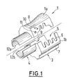
- the locking sleeve 1 shown in FIGS. 1 to 3 serves the limitation of the switching path of a switching shaft 2 which the locking sleeve 1 is fixed.
- the Locking sleeve 1 is usually not in one here shown shift dome of a vehicle transmission used.
- the locking sleeve 1 consists of two each by embossing manufactured half-shells 1a, 1b and has a pot 3 and a tubular shaft section 4 adjoining this on.
- a backdrop 5 is formed over which the Switching movement of the control shaft 2 is limited.
- the backdrop 5 has recesses 6 for defining the individual gears Gear shift on.
- a shaft section 7 extending in the axial direction trained, via which the switching level is determined.
- a Undercut 8 to define the selection level (reverse gear) educated.
- the undercut 8 can be made with a ball catch not shown, fixed to the housing work together.
- a bore 9 is formed, in which for Fixing the control shaft 2 a bolt, not shown can intervene, for example, by various adjustment processes to be carried out on the gearbox.
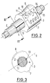
- the division plane T (cf. FIG. 3) of the locking sleeve 1 runs through the backdrop 5 and the bore 9. Because the edges 12a, b of the half-shells 1a, b, for example by laser cutting be prepared for the welded joint 13 can, by appropriate guidance of the cutting tool with the edge processing the backdrop 5 or the Bore 9 can be cut into the edges 12a, b.
- the Edges 12a, b are in particular in the area of the backdrop 5 so conical that they are slightly inward converge, which are circuit-related advantages offers.
- the half-shells 1a, b can be embossed and processed the edges 12a, b by welding, in particular laser or Electron beam welding at least in the area of the shaft section 4 can be connected.
- upper area 14 of the pot 3 another weld connection point or area 15 provided to bend the To prevent locking sleeve when switching.
- On the Inside of the shaft section 4 is then by a mechanical processing step, for example drilling or Turn, made a snug fit.
- the locking sleeve can then be shrunk onto the control shaft 2.
- the locking sleeve 20 is constructed similarly to that Locking sleeve 1 according to the first embodiment and consists of two half-shells 20a, b.
- the Locking sleeve 1 according to the first embodiment has the Locking sleeve 20 no shaft section, but consists solely of the pot 23, which has a lateral surface 24 and has a bottom surface 25.
- the bottom surface 25 is one Recess 26 formed for receiving the shift shaft 22.
- connection is preferably made by means of Laser or electron beam welding. Otherwise corresponds the locking sleeve 20 of the locking sleeve 1.
- the shaft section 4 is dispensed with Locking sleeve 20 further simplified, with the Attach the locking sleeve 20 to the collar 27 of the selector shaft 22 a reliable connection between the control shaft 22 and Locking sleeve 20 is reached.
- On the mechanical Post-processing of the inner surface of the shaft section 4 for Manufacture of a snug fit can be dispensed with, since thatshrinking the shaft section 4 onto the selector shaft not applicable.
- one of the second embodiment is minor modified embodiment of a locking sleeve 30 shown, which in contrast to the locking sleeve 20 none Setting and no mounting hole for locking plates having. Otherwise, the half-shells are connected 30a, b with each other and with the selector shaft as well in the locking sleeve 20 according to the second embodiment. On the backdrop 5 and the mounting holes 10, 11 can of course also with the locking sleeve 1 according to the first embodiment can be dispensed with.
- the locking sleeve 1; 20; 30 can be easy manufactured and reliably connected to the control shaft 2 become.
- the two-part design as half shells 1a, b; 20a, b; 30a, b allows extensive constructive design options.
Landscapes
- Engineering & Computer Science (AREA)
- General Engineering & Computer Science (AREA)
- Mechanical Engineering (AREA)
- Gear-Shifting Mechanisms (AREA)
- Mechanical Operated Clutches (AREA)
- Welding Or Cutting Using Electron Beams (AREA)
- General Details Of Gearings (AREA)
- Mechanical Control Devices (AREA)
- Multiple-Way Valves (AREA)
Applications Claiming Priority (2)
| Application Number | Priority Date | Filing Date | Title |
|---|---|---|---|
| DE19832786A DE19832786B4 (de) | 1998-07-22 | 1998-07-22 | Rastierungshülse |
| DE19832786 | 1998-07-22 |
Publications (2)
| Publication Number | Publication Date |
|---|---|
| EP0974777A2 true EP0974777A2 (fr) | 2000-01-26 |
| EP0974777A3 EP0974777A3 (fr) | 2002-01-02 |
Family
ID=7874815
Family Applications (1)
| Application Number | Title | Priority Date | Filing Date |
|---|---|---|---|
| EP99112495A Withdrawn EP0974777A3 (fr) | 1998-07-22 | 1999-07-01 | Manchon d'arrêt et arbre de sélection sur lequel est monté ledit manchon d'arrêt |
Country Status (6)
| Country | Link |
|---|---|
| EP (1) | EP0974777A3 (fr) |
| JP (1) | JP2000088099A (fr) |
| CN (1) | CN1158465C (fr) |
| AR (1) | AR023030A1 (fr) |
| DE (2) | DE19832786B4 (fr) |
| SK (1) | SK93299A3 (fr) |
Cited By (7)
| Publication number | Priority date | Publication date | Assignee | Title |
|---|---|---|---|---|
| EP0985857A2 (fr) * | 1998-09-07 | 2000-03-15 | INA Wälzlager Schaeffler oHG | Manchon d'immobilisation d'un arbre de commande |
| FR2818726A1 (fr) * | 2000-12-22 | 2002-06-28 | Schaeffler Waelzlager Ohg | Installation de commutation d'une boite de vitesses pour selectionner et commuter des rapports de vitesse |
| WO2005049264A1 (fr) * | 2003-11-19 | 2005-06-02 | Fsg Automotive Ag | Procede de fabrication d'un manchon de verrouillage, en particulier pour une boite de vitesses |
| DE10354167B3 (de) * | 2003-11-19 | 2005-08-18 | Dieter Kirschdorf | Verfahren zur Herstellung einer Rastierungshülse, insbesondere für ein Schaltgetriebe |
| WO2010124788A1 (fr) * | 2009-04-30 | 2010-11-04 | Koki Technik Transmission Systems Gmbh | Dispositif d'encliquetage, en particulier pour arbre de sélection des vitesses |
| WO2013030281A1 (fr) * | 2011-09-02 | 2013-03-07 | Koki Technik Transmission Systems Gmbh | Dispositif de verrouillage pour un mécanisme de changement de vitesse |
| WO2017157387A1 (fr) * | 2016-03-18 | 2017-09-21 | Schaeffler Technologies AG & Co. KG | Procédé de fabrication d'une douille de commande pour une boîte de vitesses à engrenages |
Families Citing this family (19)
| Publication number | Priority date | Publication date | Assignee | Title |
|---|---|---|---|---|
| DE10006721A1 (de) * | 2000-02-15 | 2001-08-16 | Schaeffler Waelzlager Ohg | Schaltvorrichtung eines Wechselgetriebes mit Dämpfungselement und Schaltwegbegrenzung |
| DE10209227A1 (de) * | 2002-03-04 | 2003-10-02 | Kochendoerfer & Kiep Stanz Und | Verfahren zum Herstellen einer Schaltgabel |
| DE102005027409B4 (de) * | 2005-06-02 | 2010-12-02 | Koki Technik Transmission Systems Gmbh | Rastierungshülse |
| DE102008013227B4 (de) | 2008-03-07 | 2014-06-05 | Koki Technik Transmission Systems Gmbh | Verfahren zum Herstellen einer Verbindung eines Getriebebauteils |
| DE102008052139B4 (de) * | 2008-10-20 | 2012-10-04 | Koki Technik Transmission Systems Gmbh | Schaltgetriebe |
| DE102009048876A1 (de) * | 2009-10-09 | 2011-04-14 | Schaeffler Technologies Gmbh & Co. Kg | Schaltvorrichtung |
| JP5472729B2 (ja) * | 2010-02-24 | 2014-04-16 | 株式会社ジェイテクト | 変速装置 |
| DE102010018655B4 (de) * | 2010-04-28 | 2022-03-31 | Koki Technik Transmission Systems Gmbh | Einteilige Rastierungshülse und ein Schaltgetriebe |
| AT510037B1 (de) | 2010-07-26 | 2012-01-15 | Stiwa Holding Gmbh | Mehrteilige rastierungshülse und verfahren zu deren herstellung |
| DE102010061514A1 (de) * | 2010-12-23 | 2012-06-28 | Dr. Ing. H.C. F. Porsche Aktiengesellschaft | Verfahren zum Herstellen einer Schaltkulisse, Schaltkulisse sowie Verbrennungsmotor |
| DE102011004415B4 (de) * | 2011-02-18 | 2023-02-16 | Schaeffler Technologies AG & Co. KG | Schaltwelle mit einer offenen Hülse sowie Hülse einer Schaltvorrichtung und Verfahren zu ihrer Herstellung |
| DE102012100236A1 (de) * | 2012-01-12 | 2013-07-18 | Koki Technik Transmission Systems Gmbh | Verfahren zur Herstellung eines Schaltrohres und ein Schaltrohr, sowie Verwendung des Schaltrohrs |
| DE102012219085A1 (de) * | 2012-10-19 | 2014-04-24 | Schaeffler Technologies Gmbh & Co. Kg | Schaltvorrichtung eines Kraftfahrzeugwechselgetriebes |
| DE102012219084A1 (de) * | 2012-10-19 | 2014-04-24 | Schaeffler Technologies Gmbh & Co. Kg | Schaltvorrichtung eines Kraftfahrzeugwechselgetriebes |
| DE102015103159A1 (de) * | 2015-03-04 | 2016-09-08 | Koki Technik Transmission Systems Gmbh | Verfahren zur Herstellung einer Rastierungshülse |
| DE102016217578A1 (de) | 2015-09-17 | 2017-03-23 | Schaeffler Technologies AG & Co. KG | Schaltvorrichtung |
| CN108018998A (zh) * | 2016-11-04 | 2018-05-11 | 柳州欧维姆机械股份有限公司 | 一种组合成型连接灌浆套筒及其制作方法 |
| DE202017100379U1 (de) | 2017-01-25 | 2017-05-17 | Koki Technik Transmission Systems Gmbh | Schaltung für ein Schaltgetriebe und Arretierungselement für einen Schaltdeckel einer Kraftfahrzeugschaltung |
| DE102017101362A1 (de) | 2017-01-25 | 2018-07-26 | Koki Technik Transmission Systems Gmbh | Schaltung für ein Schaltgetriebe und Arretierungselement für einen Schaltdeckel einer Kraftfahrzeugschaltung |
Family Cites Families (5)
| Publication number | Priority date | Publication date | Assignee | Title |
|---|---|---|---|---|
| US1350829A (en) * | 1919-01-15 | 1920-08-24 | Thomas E Murray | Method of making a plurality of like tubular objects |
| JPS6026858A (ja) * | 1983-07-20 | 1985-02-09 | Koyo Seiki Kk | チエンジドラムの製造方法 |
| JPS6026857A (ja) * | 1983-07-20 | 1985-02-09 | Koyo Seiki Kk | チエンジドラムの製造方法 |
| DE9412122U1 (de) * | 1994-07-27 | 1994-09-22 | Schaeffler Waelzlager Kg | Rastierhülse für die Sicherung von Verstellpositionen eines Stellelementes, insbesondere eines Schaltgestänges für Kraftfahrzeuge |
| DE29615599U1 (de) * | 1996-09-06 | 1996-11-28 | Schaeffler Waelzlager Kg | Sperrsystem für eine mechanische Getriebeschaltung |
-
1998
- 1998-07-22 DE DE19832786A patent/DE19832786B4/de not_active Expired - Lifetime
- 1998-08-25 DE DE29815202U patent/DE29815202U1/de not_active Expired - Lifetime
-
1999
- 1999-07-01 EP EP99112495A patent/EP0974777A3/fr not_active Withdrawn
- 1999-07-09 SK SK93299A patent/SK93299A3/sk unknown
- 1999-07-15 JP JP20205699A patent/JP2000088099A/ja active Pending
- 1999-07-21 AR ARP990103584 patent/AR023030A1/es unknown
- 1999-07-22 CN CNB991106369A patent/CN1158465C/zh not_active Expired - Lifetime
Non-Patent Citations (1)
| Title |
|---|
| None |
Cited By (8)
| Publication number | Priority date | Publication date | Assignee | Title |
|---|---|---|---|---|
| EP0985857A2 (fr) * | 1998-09-07 | 2000-03-15 | INA Wälzlager Schaeffler oHG | Manchon d'immobilisation d'un arbre de commande |
| EP0985857A3 (fr) * | 1998-09-07 | 2000-09-13 | INA Wälzlager Schaeffler oHG | Manchon d'immobilisation d'un arbre de commande |
| FR2818726A1 (fr) * | 2000-12-22 | 2002-06-28 | Schaeffler Waelzlager Ohg | Installation de commutation d'une boite de vitesses pour selectionner et commuter des rapports de vitesse |
| WO2005049264A1 (fr) * | 2003-11-19 | 2005-06-02 | Fsg Automotive Ag | Procede de fabrication d'un manchon de verrouillage, en particulier pour une boite de vitesses |
| DE10354167B3 (de) * | 2003-11-19 | 2005-08-18 | Dieter Kirschdorf | Verfahren zur Herstellung einer Rastierungshülse, insbesondere für ein Schaltgetriebe |
| WO2010124788A1 (fr) * | 2009-04-30 | 2010-11-04 | Koki Technik Transmission Systems Gmbh | Dispositif d'encliquetage, en particulier pour arbre de sélection des vitesses |
| WO2013030281A1 (fr) * | 2011-09-02 | 2013-03-07 | Koki Technik Transmission Systems Gmbh | Dispositif de verrouillage pour un mécanisme de changement de vitesse |
| WO2017157387A1 (fr) * | 2016-03-18 | 2017-09-21 | Schaeffler Technologies AG & Co. KG | Procédé de fabrication d'une douille de commande pour une boîte de vitesses à engrenages |
Also Published As
| Publication number | Publication date |
|---|---|
| DE19832786A1 (de) | 2000-02-03 |
| EP0974777A3 (fr) | 2002-01-02 |
| DE29815202U1 (de) | 1998-11-05 |
| DE19832786B4 (de) | 2010-01-07 |
| CN1158465C (zh) | 2004-07-21 |
| JP2000088099A (ja) | 2000-03-28 |
| CN1252499A (zh) | 2000-05-10 |
| SK93299A3 (en) | 2000-05-16 |
| AR023030A1 (es) | 2002-09-04 |
Similar Documents
| Publication | Publication Date | Title |
|---|---|---|
| EP0974777A2 (fr) | Manchon d'arrêt et arbre de sélection sur lequel est monté ledit manchon d'arrêt | |
| EP0955481B1 (fr) | Manchon de changement de vitesses d'un assemblage de synchronisation pour une boíte de vitesses | |
| WO1999041529A1 (fr) | Boite de vitesses avec arbre de selection central | |
| WO2011029559A1 (fr) | Ensemble comportant deux bagues de synchronisation | |
| WO1996003684A1 (fr) | Manchon d'encliquetage pour proteger les positions de reglage d'un element de reglage, notamment d'une tringlerie de changement de vitesses pour automobile | |
| EP2288826B1 (fr) | PROCÉDÉ DE FABRICATION Du DISPOSITIF DE DOIGT DE CHANGEMENT DE VITESSES | |
| EP1969259B1 (fr) | Arrangement de changement de rapport comportant une fourchette de boîte de vitesses | |
| DE19581000B4 (de) | Übertragungselement für eine Getriebeschaltung | |
| DE102010018655B4 (de) | Einteilige Rastierungshülse und ein Schaltgetriebe | |
| DE10012382B4 (de) | Handschalthebel für ein Fahrzeugwechselgetriebe | |
| DE102005053989B4 (de) | Verfahren zur Herstellung eines Kupplungskörpers | |
| DE3808025A1 (de) | Schalthebel | |
| EP1734290B1 (fr) | Dispositif d'actionnement d'un manchon d'accouplement d'une boîte de vitesses | |
| DE102005039752A1 (de) | Schalteinrichtung mit Schaltgabel und Schaltarretierung | |
| DE102010036277B4 (de) | Kupplungskörper für ein Gangrad eines Schaltgetriebes sowie Gangrad mit Kupplungskörper | |
| EP2132464B1 (fr) | Barillet de sélection | |
| AT510576B1 (de) | Lagereinheit für eine schaltvorrichtung eines kraftfahrzeuggetriebes | |
| DE102014107767B3 (de) | Schaltwellenmodul zum Schalten von Gängen in einem Schaltgetriebe | |
| DE102006001229B4 (de) | Schaltgabelanordnung für Kraftfahrzeug-Schaltgetriebe | |
| EP2334957A1 (fr) | Dispositif de commutation pour une boîte de vitesses | |
| DE10029620A1 (de) | Schaltwelle für ein Schaltgetriebe und Verfahren zu ihrer Herstellung | |
| DE19921625A1 (de) | Schalteinrichtung für ein Wechselgetriebe eines Kraftfahrzeuges | |
| EP1262693A2 (fr) | Tige de commande de fourchettes avec fourchette de commande de changement de vitesses | |
| DE102006057462A1 (de) | Schaltvorrichtung | |
| DE102016217578A1 (de) | Schaltvorrichtung |
Legal Events
| Date | Code | Title | Description |
|---|---|---|---|
| PUAI | Public reference made under article 153(3) epc to a published international application that has entered the european phase |
Free format text: ORIGINAL CODE: 0009012 |
|
| AK | Designated contracting states |
Kind code of ref document: A2 Designated state(s): AT BE CH CY DE DK ES FI FR GB GR IE IT LI LU MC NL PT SE |
|
| AX | Request for extension of the european patent |
Free format text: AL;LT;LV;MK;RO;SI |
|
| PUAL | Search report despatched |
Free format text: ORIGINAL CODE: 0009013 |
|
| STAA | Information on the status of an ep patent application or granted ep patent |
Free format text: STATUS: THE APPLICATION HAS BEEN WITHDRAWN |
|
| 18W | Application withdrawn |
Withdrawal date: 20011026 |
|
| AK | Designated contracting states |
Kind code of ref document: A3 Designated state(s): AT BE CH CY DE DK ES FI FR GB GR IE IT LI LU MC NL PT SE |
|
| AX | Request for extension of the european patent |
Free format text: AL;LT;LV;MK;RO;SI |