EP0973469B1 - Flexible, berührungsfreie wundbehandlungsvorrichtung mit einer einfachen verbindung - Google Patents
Flexible, berührungsfreie wundbehandlungsvorrichtung mit einer einfachen verbindung Download PDFInfo
- Publication number
- EP0973469B1 EP0973469B1 EP98902779A EP98902779A EP0973469B1 EP 0973469 B1 EP0973469 B1 EP 0973469B1 EP 98902779 A EP98902779 A EP 98902779A EP 98902779 A EP98902779 A EP 98902779A EP 0973469 B1 EP0973469 B1 EP 0973469B1
- Authority
- EP
- European Patent Office
- Prior art keywords
- wound treatment
- treatment device
- standoff
- wound
- contact wound
- Prior art date
- Legal status (The legal status is an assumption and is not a legal conclusion. Google has not performed a legal analysis and makes no representation as to the accuracy of the status listed.)
- Expired - Lifetime
Links
- 206010052428 Wound Diseases 0.000 title claims abstract description 238
- 208000027418 Wounds and injury Diseases 0.000 title claims abstract description 238
- 230000007704 transition Effects 0.000 claims abstract description 73
- 239000000463 material Substances 0.000 claims description 14
- 238000012546 transfer Methods 0.000 claims description 4
- 230000002745 absorbent Effects 0.000 claims description 3
- 239000002250 absorbent Substances 0.000 claims description 3
- 230000005540 biological transmission Effects 0.000 claims description 3
- 239000006261 foam material Substances 0.000 claims description 3
- 230000005855 radiation Effects 0.000 claims description 3
- QVGXLLKOCUKJST-UHFFFAOYSA-N atomic oxygen Chemical compound [O] QVGXLLKOCUKJST-UHFFFAOYSA-N 0.000 claims description 2
- 229910052760 oxygen Inorganic materials 0.000 claims description 2
- 239000001301 oxygen Substances 0.000 claims description 2
- 230000035699 permeability Effects 0.000 claims description 2
- 229920006267 polyester film Polymers 0.000 claims description 2
- 229920006264 polyurethane film Polymers 0.000 claims description 2
- JOYRKODLDBILNP-UHFFFAOYSA-N urethane group Chemical group NC(=O)OCC JOYRKODLDBILNP-UHFFFAOYSA-N 0.000 claims description 2
- 239000012530 fluid Substances 0.000 claims 4
- 239000006260 foam Substances 0.000 description 26
- 239000010410 layer Substances 0.000 description 20
- 230000033001 locomotion Effects 0.000 description 17
- 239000000853 adhesive Substances 0.000 description 11
- 230000001070 adhesive effect Effects 0.000 description 11
- 239000012528 membrane Substances 0.000 description 9
- 239000002131 composite material Substances 0.000 description 7
- 238000010438 heat treatment Methods 0.000 description 7
- 238000010276 construction Methods 0.000 description 6
- 230000009467 reduction Effects 0.000 description 4
- 239000004698 Polyethylene Substances 0.000 description 3
- 230000008901 benefit Effects 0.000 description 3
- -1 polyethylene Polymers 0.000 description 3
- 229920000573 polyethylene Polymers 0.000 description 3
- MWUXSHHQAYIFBG-UHFFFAOYSA-N Nitric oxide Chemical compound O=[N] MWUXSHHQAYIFBG-UHFFFAOYSA-N 0.000 description 2
- 229920005830 Polyurethane Foam Polymers 0.000 description 2
- 239000002313 adhesive film Substances 0.000 description 2
- 230000004888 barrier function Effects 0.000 description 2
- 230000002349 favourable effect Effects 0.000 description 2
- 239000010408 film Substances 0.000 description 2
- 230000003902 lesion Effects 0.000 description 2
- 238000000034 method Methods 0.000 description 2
- 238000000465 moulding Methods 0.000 description 2
- 239000011496 polyurethane foam Substances 0.000 description 2
- 230000011514 reflex Effects 0.000 description 2
- 230000004044 response Effects 0.000 description 2
- 230000004308 accommodation Effects 0.000 description 1
- 238000004026 adhesive bonding Methods 0.000 description 1
- 239000012790 adhesive layer Substances 0.000 description 1
- 239000003242 anti bacterial agent Substances 0.000 description 1
- 230000000843 anti-fungal effect Effects 0.000 description 1
- 230000000845 anti-microbial effect Effects 0.000 description 1
- 229940121375 antifungal agent Drugs 0.000 description 1
- 230000003115 biocidal effect Effects 0.000 description 1
- MAEIEVLCKWDQJH-UHFFFAOYSA-N bumetanide Chemical compound CCCCNC1=CC(C(O)=O)=CC(S(N)(=O)=O)=C1OC1=CC=CC=C1 MAEIEVLCKWDQJH-UHFFFAOYSA-N 0.000 description 1
- 230000008859 change Effects 0.000 description 1
- 230000006735 deficit Effects 0.000 description 1
- 239000002781 deodorant agent Substances 0.000 description 1
- 238000010586 diagram Methods 0.000 description 1
- 239000003814 drug Substances 0.000 description 1
- 230000002708 enhancing effect Effects 0.000 description 1
- 210000000416 exudates and transudate Anatomy 0.000 description 1
- 230000004907 flux Effects 0.000 description 1
- 238000011065 in-situ storage Methods 0.000 description 1
- 238000003780 insertion Methods 0.000 description 1
- 230000037431 insertion Effects 0.000 description 1
- 238000009413 insulation Methods 0.000 description 1
- 239000012212 insulator Substances 0.000 description 1
- 230000002262 irrigation Effects 0.000 description 1
- 238000003973 irrigation Methods 0.000 description 1
- 238000005304 joining Methods 0.000 description 1
- 238000002803 maceration Methods 0.000 description 1
- 238000004519 manufacturing process Methods 0.000 description 1
- 238000013507 mapping Methods 0.000 description 1
- 230000007246 mechanism Effects 0.000 description 1
- 238000012986 modification Methods 0.000 description 1
- 230000004048 modification Effects 0.000 description 1
- 238000013021 overheating Methods 0.000 description 1
- 239000002984 plastic foam Substances 0.000 description 1
- 229920000728 polyester Polymers 0.000 description 1
- 229920000098 polyolefin Polymers 0.000 description 1
- 230000008569 process Effects 0.000 description 1
- 230000001681 protective effect Effects 0.000 description 1
- 239000012858 resilient material Substances 0.000 description 1
- 238000007789 sealing Methods 0.000 description 1
- 238000010008 shearing Methods 0.000 description 1
- 229920003051 synthetic elastomer Polymers 0.000 description 1
- 239000005061 synthetic rubber Substances 0.000 description 1
- 239000010409 thin film Substances 0.000 description 1
- 238000003466 welding Methods 0.000 description 1
- 230000029663 wound healing Effects 0.000 description 1
Images


Classifications
-
- A—HUMAN NECESSITIES
- A61—MEDICAL OR VETERINARY SCIENCE; HYGIENE
- A61F—FILTERS IMPLANTABLE INTO BLOOD VESSELS; PROSTHESES; DEVICES PROVIDING PATENCY TO, OR PREVENTING COLLAPSING OF, TUBULAR STRUCTURES OF THE BODY, e.g. STENTS; ORTHOPAEDIC, NURSING OR CONTRACEPTIVE DEVICES; FOMENTATION; TREATMENT OR PROTECTION OF EYES OR EARS; BANDAGES, DRESSINGS OR ABSORBENT PADS; FIRST-AID KITS
- A61F7/00—Heating or cooling appliances for medical or therapeutic treatment of the human body
- A61F7/007—Heating or cooling appliances for medical or therapeutic treatment of the human body characterised by electric heating
-
- A—HUMAN NECESSITIES
- A61—MEDICAL OR VETERINARY SCIENCE; HYGIENE
- A61F—FILTERS IMPLANTABLE INTO BLOOD VESSELS; PROSTHESES; DEVICES PROVIDING PATENCY TO, OR PREVENTING COLLAPSING OF, TUBULAR STRUCTURES OF THE BODY, e.g. STENTS; ORTHOPAEDIC, NURSING OR CONTRACEPTIVE DEVICES; FOMENTATION; TREATMENT OR PROTECTION OF EYES OR EARS; BANDAGES, DRESSINGS OR ABSORBENT PADS; FIRST-AID KITS
- A61F15/00—Auxiliary appliances for wound dressings; Dispensing containers for dressings or bandages
- A61F15/008—Appliances for wound protecting, e.g. avoiding contact between wound and bandage
-
- A—HUMAN NECESSITIES
- A61—MEDICAL OR VETERINARY SCIENCE; HYGIENE
- A61F—FILTERS IMPLANTABLE INTO BLOOD VESSELS; PROSTHESES; DEVICES PROVIDING PATENCY TO, OR PREVENTING COLLAPSING OF, TUBULAR STRUCTURES OF THE BODY, e.g. STENTS; ORTHOPAEDIC, NURSING OR CONTRACEPTIVE DEVICES; FOMENTATION; TREATMENT OR PROTECTION OF EYES OR EARS; BANDAGES, DRESSINGS OR ABSORBENT PADS; FIRST-AID KITS
- A61F7/00—Heating or cooling appliances for medical or therapeutic treatment of the human body
- A61F7/007—Heating or cooling appliances for medical or therapeutic treatment of the human body characterised by electric heating
- A61F2007/0071—Heating or cooling appliances for medical or therapeutic treatment of the human body characterised by electric heating using a resistor, e.g. near the spot to be heated
-
- A—HUMAN NECESSITIES
- A61—MEDICAL OR VETERINARY SCIENCE; HYGIENE
- A61F—FILTERS IMPLANTABLE INTO BLOOD VESSELS; PROSTHESES; DEVICES PROVIDING PATENCY TO, OR PREVENTING COLLAPSING OF, TUBULAR STRUCTURES OF THE BODY, e.g. STENTS; ORTHOPAEDIC, NURSING OR CONTRACEPTIVE DEVICES; FOMENTATION; TREATMENT OR PROTECTION OF EYES OR EARS; BANDAGES, DRESSINGS OR ABSORBENT PADS; FIRST-AID KITS
- A61F7/00—Heating or cooling appliances for medical or therapeutic treatment of the human body
- A61F7/007—Heating or cooling appliances for medical or therapeutic treatment of the human body characterised by electric heating
- A61F2007/0077—Details of power supply
- A61F2007/0078—Details of power supply with a battery
-
- A—HUMAN NECESSITIES
- A61—MEDICAL OR VETERINARY SCIENCE; HYGIENE
- A61F—FILTERS IMPLANTABLE INTO BLOOD VESSELS; PROSTHESES; DEVICES PROVIDING PATENCY TO, OR PREVENTING COLLAPSING OF, TUBULAR STRUCTURES OF THE BODY, e.g. STENTS; ORTHOPAEDIC, NURSING OR CONTRACEPTIVE DEVICES; FOMENTATION; TREATMENT OR PROTECTION OF EYES OR EARS; BANDAGES, DRESSINGS OR ABSORBENT PADS; FIRST-AID KITS
- A61F7/00—Heating or cooling appliances for medical or therapeutic treatment of the human body
- A61F2007/0088—Radiating heat
-
- A—HUMAN NECESSITIES
- A61—MEDICAL OR VETERINARY SCIENCE; HYGIENE
- A61F—FILTERS IMPLANTABLE INTO BLOOD VESSELS; PROSTHESES; DEVICES PROVIDING PATENCY TO, OR PREVENTING COLLAPSING OF, TUBULAR STRUCTURES OF THE BODY, e.g. STENTS; ORTHOPAEDIC, NURSING OR CONTRACEPTIVE DEVICES; FOMENTATION; TREATMENT OR PROTECTION OF EYES OR EARS; BANDAGES, DRESSINGS OR ABSORBENT PADS; FIRST-AID KITS
- A61F13/00—Bandages or dressings; Absorbent pads
- A61F2013/00089—Wound bandages
- A61F2013/00165—Wound bandages not touching the wound
-
- A—HUMAN NECESSITIES
- A61—MEDICAL OR VETERINARY SCIENCE; HYGIENE
- A61F—FILTERS IMPLANTABLE INTO BLOOD VESSELS; PROSTHESES; DEVICES PROVIDING PATENCY TO, OR PREVENTING COLLAPSING OF, TUBULAR STRUCTURES OF THE BODY, e.g. STENTS; ORTHOPAEDIC, NURSING OR CONTRACEPTIVE DEVICES; FOMENTATION; TREATMENT OR PROTECTION OF EYES OR EARS; BANDAGES, DRESSINGS OR ABSORBENT PADS; FIRST-AID KITS
- A61F13/00—Bandages or dressings; Absorbent pads
- A61F2013/00089—Wound bandages
- A61F2013/00182—Wound bandages with transparent part
-
- A—HUMAN NECESSITIES
- A61—MEDICAL OR VETERINARY SCIENCE; HYGIENE
- A61F—FILTERS IMPLANTABLE INTO BLOOD VESSELS; PROSTHESES; DEVICES PROVIDING PATENCY TO, OR PREVENTING COLLAPSING OF, TUBULAR STRUCTURES OF THE BODY, e.g. STENTS; ORTHOPAEDIC, NURSING OR CONTRACEPTIVE DEVICES; FOMENTATION; TREATMENT OR PROTECTION OF EYES OR EARS; BANDAGES, DRESSINGS OR ABSORBENT PADS; FIRST-AID KITS
- A61F13/00—Bandages or dressings; Absorbent pads
- A61F2013/00089—Wound bandages
- A61F2013/00187—Wound bandages insulating; warmth or cold applying
- A61F2013/00195—Wound bandages insulating; warmth or cold applying electric warmer
-
- A—HUMAN NECESSITIES
- A61—MEDICAL OR VETERINARY SCIENCE; HYGIENE
- A61F—FILTERS IMPLANTABLE INTO BLOOD VESSELS; PROSTHESES; DEVICES PROVIDING PATENCY TO, OR PREVENTING COLLAPSING OF, TUBULAR STRUCTURES OF THE BODY, e.g. STENTS; ORTHOPAEDIC, NURSING OR CONTRACEPTIVE DEVICES; FOMENTATION; TREATMENT OR PROTECTION OF EYES OR EARS; BANDAGES, DRESSINGS OR ABSORBENT PADS; FIRST-AID KITS
- A61F13/00—Bandages or dressings; Absorbent pads
- A61F2013/00089—Wound bandages
- A61F2013/00187—Wound bandages insulating; warmth or cold applying
- A61F2013/002—Wound bandages insulating; warmth or cold applying with temperature control
-
- A—HUMAN NECESSITIES
- A61—MEDICAL OR VETERINARY SCIENCE; HYGIENE
- A61F—FILTERS IMPLANTABLE INTO BLOOD VESSELS; PROSTHESES; DEVICES PROVIDING PATENCY TO, OR PREVENTING COLLAPSING OF, TUBULAR STRUCTURES OF THE BODY, e.g. STENTS; ORTHOPAEDIC, NURSING OR CONTRACEPTIVE DEVICES; FOMENTATION; TREATMENT OR PROTECTION OF EYES OR EARS; BANDAGES, DRESSINGS OR ABSORBENT PADS; FIRST-AID KITS
- A61F13/00—Bandages or dressings; Absorbent pads
- A61F2013/00089—Wound bandages
- A61F2013/00187—Wound bandages insulating; warmth or cold applying
- A61F2013/00204—Wound bandages insulating; warmth or cold applying insulating
- A61F2013/00212—Wound bandages insulating; warmth or cold applying insulating infrared absorbing or reflecting
-
- A—HUMAN NECESSITIES
- A61—MEDICAL OR VETERINARY SCIENCE; HYGIENE
- A61F—FILTERS IMPLANTABLE INTO BLOOD VESSELS; PROSTHESES; DEVICES PROVIDING PATENCY TO, OR PREVENTING COLLAPSING OF, TUBULAR STRUCTURES OF THE BODY, e.g. STENTS; ORTHOPAEDIC, NURSING OR CONTRACEPTIVE DEVICES; FOMENTATION; TREATMENT OR PROTECTION OF EYES OR EARS; BANDAGES, DRESSINGS OR ABSORBENT PADS; FIRST-AID KITS
- A61F13/00—Bandages or dressings; Absorbent pads
- A61F2013/00361—Plasters
- A61F2013/00365—Plasters use
- A61F2013/00387—Plasters use skin protection
-
- A—HUMAN NECESSITIES
- A61—MEDICAL OR VETERINARY SCIENCE; HYGIENE
- A61F—FILTERS IMPLANTABLE INTO BLOOD VESSELS; PROSTHESES; DEVICES PROVIDING PATENCY TO, OR PREVENTING COLLAPSING OF, TUBULAR STRUCTURES OF THE BODY, e.g. STENTS; ORTHOPAEDIC, NURSING OR CONTRACEPTIVE DEVICES; FOMENTATION; TREATMENT OR PROTECTION OF EYES OR EARS; BANDAGES, DRESSINGS OR ABSORBENT PADS; FIRST-AID KITS
- A61F13/00—Bandages or dressings; Absorbent pads
- A61F2013/00361—Plasters
- A61F2013/00544—Plasters form or structure
- A61F2013/00553—Plasters form or structure with detachable parts
- A61F2013/00561—Plasters form or structure with detachable parts with adhesive connecting means
-
- A—HUMAN NECESSITIES
- A61—MEDICAL OR VETERINARY SCIENCE; HYGIENE
- A61F—FILTERS IMPLANTABLE INTO BLOOD VESSELS; PROSTHESES; DEVICES PROVIDING PATENCY TO, OR PREVENTING COLLAPSING OF, TUBULAR STRUCTURES OF THE BODY, e.g. STENTS; ORTHOPAEDIC, NURSING OR CONTRACEPTIVE DEVICES; FOMENTATION; TREATMENT OR PROTECTION OF EYES OR EARS; BANDAGES, DRESSINGS OR ABSORBENT PADS; FIRST-AID KITS
- A61F13/00—Bandages or dressings; Absorbent pads
- A61F2013/00361—Plasters
- A61F2013/00544—Plasters form or structure
- A61F2013/00553—Plasters form or structure with detachable parts
- A61F2013/00565—Plasters form or structure with detachable parts with hook and loop-type fastener connecting means
-
- A—HUMAN NECESSITIES
- A61—MEDICAL OR VETERINARY SCIENCE; HYGIENE
- A61F—FILTERS IMPLANTABLE INTO BLOOD VESSELS; PROSTHESES; DEVICES PROVIDING PATENCY TO, OR PREVENTING COLLAPSING OF, TUBULAR STRUCTURES OF THE BODY, e.g. STENTS; ORTHOPAEDIC, NURSING OR CONTRACEPTIVE DEVICES; FOMENTATION; TREATMENT OR PROTECTION OF EYES OR EARS; BANDAGES, DRESSINGS OR ABSORBENT PADS; FIRST-AID KITS
- A61F13/00—Bandages or dressings; Absorbent pads
- A61F2013/00361—Plasters
- A61F2013/00544—Plasters form or structure
- A61F2013/0057—Plasters form or structure with openable cover
-
- A—HUMAN NECESSITIES
- A61—MEDICAL OR VETERINARY SCIENCE; HYGIENE
- A61F—FILTERS IMPLANTABLE INTO BLOOD VESSELS; PROSTHESES; DEVICES PROVIDING PATENCY TO, OR PREVENTING COLLAPSING OF, TUBULAR STRUCTURES OF THE BODY, e.g. STENTS; ORTHOPAEDIC, NURSING OR CONTRACEPTIVE DEVICES; FOMENTATION; TREATMENT OR PROTECTION OF EYES OR EARS; BANDAGES, DRESSINGS OR ABSORBENT PADS; FIRST-AID KITS
- A61F13/00—Bandages or dressings; Absorbent pads
- A61F2013/00361—Plasters
- A61F2013/00727—Plasters means for wound humidity control
- A61F2013/00731—Plasters means for wound humidity control with absorbing pads
- A61F2013/0074—Plasters means for wound humidity control with absorbing pads containing foams
-
- A—HUMAN NECESSITIES
- A61—MEDICAL OR VETERINARY SCIENCE; HYGIENE
- A61F—FILTERS IMPLANTABLE INTO BLOOD VESSELS; PROSTHESES; DEVICES PROVIDING PATENCY TO, OR PREVENTING COLLAPSING OF, TUBULAR STRUCTURES OF THE BODY, e.g. STENTS; ORTHOPAEDIC, NURSING OR CONTRACEPTIVE DEVICES; FOMENTATION; TREATMENT OR PROTECTION OF EYES OR EARS; BANDAGES, DRESSINGS OR ABSORBENT PADS; FIRST-AID KITS
- A61F13/00—Bandages or dressings; Absorbent pads
- A61F2013/00361—Plasters
- A61F2013/00795—Plasters special helping devices
- A61F2013/00817—Plasters special helping devices handles or handling tabs
-
- A—HUMAN NECESSITIES
- A61—MEDICAL OR VETERINARY SCIENCE; HYGIENE
- A61F—FILTERS IMPLANTABLE INTO BLOOD VESSELS; PROSTHESES; DEVICES PROVIDING PATENCY TO, OR PREVENTING COLLAPSING OF, TUBULAR STRUCTURES OF THE BODY, e.g. STENTS; ORTHOPAEDIC, NURSING OR CONTRACEPTIVE DEVICES; FOMENTATION; TREATMENT OR PROTECTION OF EYES OR EARS; BANDAGES, DRESSINGS OR ABSORBENT PADS; FIRST-AID KITS
- A61F13/00—Bandages or dressings; Absorbent pads
- A61F2013/00361—Plasters
- A61F2013/00846—Plasters with transparent or translucent part
-
- A—HUMAN NECESSITIES
- A61—MEDICAL OR VETERINARY SCIENCE; HYGIENE
- A61F—FILTERS IMPLANTABLE INTO BLOOD VESSELS; PROSTHESES; DEVICES PROVIDING PATENCY TO, OR PREVENTING COLLAPSING OF, TUBULAR STRUCTURES OF THE BODY, e.g. STENTS; ORTHOPAEDIC, NURSING OR CONTRACEPTIVE DEVICES; FOMENTATION; TREATMENT OR PROTECTION OF EYES OR EARS; BANDAGES, DRESSINGS OR ABSORBENT PADS; FIRST-AID KITS
- A61F13/00—Bandages or dressings; Absorbent pads
- A61F2013/00361—Plasters
- A61F2013/00902—Plasters containing means
- A61F2013/0091—Plasters containing means with disinfecting or anaesthetics means, e.g. anti-mycrobic
-
- A—HUMAN NECESSITIES
- A61—MEDICAL OR VETERINARY SCIENCE; HYGIENE
- A61F—FILTERS IMPLANTABLE INTO BLOOD VESSELS; PROSTHESES; DEVICES PROVIDING PATENCY TO, OR PREVENTING COLLAPSING OF, TUBULAR STRUCTURES OF THE BODY, e.g. STENTS; ORTHOPAEDIC, NURSING OR CONTRACEPTIVE DEVICES; FOMENTATION; TREATMENT OR PROTECTION OF EYES OR EARS; BANDAGES, DRESSINGS OR ABSORBENT PADS; FIRST-AID KITS
- A61F13/00—Bandages or dressings; Absorbent pads
- A61F2013/00361—Plasters
- A61F2013/00902—Plasters containing means
- A61F2013/00914—Plasters containing means with deodorising or perfuming means
-
- A—HUMAN NECESSITIES
- A61—MEDICAL OR VETERINARY SCIENCE; HYGIENE
- A61F—FILTERS IMPLANTABLE INTO BLOOD VESSELS; PROSTHESES; DEVICES PROVIDING PATENCY TO, OR PREVENTING COLLAPSING OF, TUBULAR STRUCTURES OF THE BODY, e.g. STENTS; ORTHOPAEDIC, NURSING OR CONTRACEPTIVE DEVICES; FOMENTATION; TREATMENT OR PROTECTION OF EYES OR EARS; BANDAGES, DRESSINGS OR ABSORBENT PADS; FIRST-AID KITS
- A61F13/00—Bandages or dressings; Absorbent pads
- A61F2013/00361—Plasters
- A61F2013/00902—Plasters containing means
- A61F2013/00919—Plasters containing means for physical therapy, e.g. cold or magnetic
Definitions
- This invention relates to a wound treatment device and, in particular, to a wound treatment device having a substantial portion of a wound cover that is in non-contact with a wound and capable of delivering heat to the wound. More particularly, the wound treatment device includes such a wound treatment device with a single joint that maximizes the ability of the wound treatment device to adapt to the contours and movements of a human body.
- a novel mode of wound treatment is disclosed in detail in published PCT Applications WO 94/00090 and WO 96/15745, both owned in common with this application.
- This new treatment employs a non-contact wound treatment device that covers a wound, forming a treatment volume about and over the wound.
- An embodiment of such a wound treatment device may be characterized in having a plurality of parts, three of which are useful for the purpose of description. These three parts are an attachment portion, a wound treatment portion, and a transition portion. Each portion serves a respective function.
- the attachment portion connects and retains the wound treatment device on the skin of a person.
- the wound treatment portion typically includes a standoff that rises above the person's skin surface, and a wound cover that spans an open portion of the standoff. Together, the standoff and wound cover define a wound treatment volume and a wound treatment area onto which the wound treatment volume is projected.
- the transition portion connects the attachment portion to the wound treatment portion.
- An important function of the transition portion is to adapt the wound treatment device to the contour of the portion of a person's body where the device is mounted and to movements of the person's body that deform the wound treatment device in situ .
- an important function of the transition portion is the accommodation of patient motion by the compliance of the transition portion.
- the transition portion is challenged by the need to maintain the orientation of the wound cover in the wound treatment portion-both in aspect and location - with respect to the wound being treated.
- the orientation of the wound cover is difficult to maintain when the wound treatment device is mounted on a highly curved part of a body.
- the wound treatment devices disclosed in the referenced PCT applications exhibit excellent adaptability in a surface that is parallel to the surface of the body portion where the wound treatment device is mounted, there is impairment of adaptability and disturbance of the orientation of the wound cover due to limited flexibility in the direction of a Z axis that is perpendicular to the surfaces.
- the transition portion is substantially perpendicular to the attachment portion, it may buckle in response to body motion or contour and collapse the standoff in the wound treatment portion. The collapse of the standoff of course alters the orientation of the wound cover with respect to the wound, possibly reducing the effectiveness of the wound treatment device.
- the overall flexibility of a wound treatment device is enhanced by an invention based upon the inventors' critical realization that provision of a joint in the transition portion that connects the wound treatment portion to the attachment portion accommodates patient motion and contour by providing articulation between these portions that permits flexion of the wound treatment device in all dimensions of the volume that the wound treatment device occupies.
- the joint connects the wound treatment portion to the attachment portion, extending between the standoff and the attachment portion.
- the joint attaches to the attachment portion under the standoff between inner and outer perimeters of the attachment portion.
- the inner perimeter of the attachment portion is limited to being contained within the outer perimeter of the standoff. This permits reduction of the size of the attachment portion, minimizing the total "foot print" of the wound treatment device. A smaller footprint is generally considered to be advantageous particularly when attaching the wound treatment device to a highly curved part of a person's body, such as the surface of a lower leg.
- an objective of this invention to provide a flexible, non-contact wound treatment device that adapts to body curvature and motion.
- Another objective is the provision of a non-contact wound treatment device having a wound treatment portion and an attachment portion, with a joint between the wound treatment and attachment portions.
- a significant advantage of the invention is the potential reduction in size of the attachment portion, providing a smaller footprint of the wound treatment device.
- FIGS. 1-140 in which embodiments and elements of a wound treatment device are illustrated.
- This device was the subject of WO96/15745.
- a wound treatment device 10 has a planar upper surface displaced above the skin surface of the patient or person having a wound that is being treated by application and operation of the device 10.
- the wound treatment device 10 further includes an attachment surface generally held in a plane or surface that is coincident with the plane or surface of the person's skin. Together these two surfaces define an enclosed, non-contact volume over a wound treatment site.
- the wound treatment device 10 that is illustrated in Fig. 1 may be considered in a general way for the purpose of description.
- the description of a wound treatment device is aided by considering three separate parts of the wound treatment device 10. These parts are an attachment portion 12, a wound treatment portion 14, and a transition portion 16. Each portion is designed to serve a separate function.
- the attachment portion 12 is used to connect the wound treatment device 10 to the skin of a patient.
- the wound treatment portion 14 of the wound treatment device 10 defines a vertical extent or dimension of the wound treatment device 10, and thus defines the location of the attachment surface.
- the transition portion 16 connects the attachment portion 12 to the wound treatment portion 14. The transition portion 16 is provided to improve the comfort and utility of the wound treatment device 10 when the patient moves and stretches the device.
- Fig. 1 is a perspective view of a wound treatment device 10 applied to a patient's skin surface 18.
- a coordinate system 11 is depicted on the patient's skin surface 18 and it defines X, Y and Z directions.
- An attachment portion 12 is formed as an planar rim or flange. This attachment portion 12 is attached to the patient's skin 18 with an adhesive and it lies in a first XY plane.
- a transition portion 16 is integrally formed with attachment portion 12. Transition portion 16 rises from the skin surface in the Z direction to connect to a wound treatment portion 14.
- wound treatment portion 14 has a transparent planar wound cover 20 which allows one to see a wound treatment area 28.
- Wound cover 20 is supported above the first XY plane by a foam ring standoff 15. Wound cover 20 lies in a second XY plane that is vertically displaced along the Z-axis by foam ring standoff 15 from the first XY plane. Wound cover 20 and foam ring standoff 15 together form wound treatment portion 14. The region over wound treatment area 28 is called a wound treatment volume 24.
- wound treatment device 10 has been applied to a patient's skin and is in a relaxed state. In this unstressed state one can see an outer periphery 22 of attachment portion 12. An inner periphery 23 is shown by a crease in the structure where it connects to transition portion 16.
- FIG. 2 and Fig. 3 should be considered together where they show the influence of patient motion on wound treatment device 10.
- Both Fig. 2 and Fig. 3 are top views of wound treatment device 10 of Fig. 1 with the various portions of wound treatment device 10 projected onto the first XY plane.
- Fig. 3 shows wound treatment device 10 stretched along the X-axis by patient motion.
- the overall or total projected area 27 of wound treatment device 10 has increased.
- Attachment portion projected area 40 has increased slightly as attachment portion 12 moves with the underlying skin.
- Projected wound enclosure area 28 is essentially unchanged in area since in this embodiment foam ring standoff 15 is free move against the skin.
- the largest percentage area change occurs in transition portion projected area 17.
- transition portion 16 is compliant and pays out material permitting the majority of the increase in total projected area 27 to be accommodated primarily by transition portion projected area 17.
- Fig. 4 shows a detachable heater 32 positioned for insertion into a pocket formed by pocket cover 21.
- Pocket cover 21 is bonded to wound cover 20 and is sized to retain heater 32.
- Foam ring standoff 15 and wound cover 20 serve to stabilize the shape of wound treatment device 10 while transition portion 16 accommodates patient motion. Consequently, heater 32 is reliably and comfortably positioned above the wound surface.
- the amount of heat supplied to the wound area is largely independent of the height of heater 32 above the wound surface within the range of functional heights of this device. In some cases, non-uniform wound area heating might be desirable and therefore the watt density of the heater may be non-uniform across its surface.
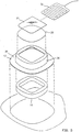
- Fig. 5 is an exploded view of the first embodiment of wound treatment device 10.
- Attachment portion 12 and transition portion membrane 36 are formed as a unitary composite shell 38.
- Composite shell 38 may be vacuum formed from closed cell polyolefin foams such as Volara-6AS, which is a polyethylene material as sold by Illbruck Inc., of Minneapolis, Minnesota. It should be apparent that many other materials may be substituted.
- Foam ring standoff 15 may be die cut from foam sheeting of a reticulated polyurethane foam. The absorbency of the foam as well as its mechanical properties can be tailored to the particular wound treatment application. For example, the foam standoff may be impregnated with a medicament such as an antibiotic, antifungal, or antimicrobial material.
- Wound cover 20 and wound pocket 21 may be made from a thin film of polyethylene.
- the composite shell should be sufficiently self supporting so that when wound treatment device 10 is removed from its release liner, wound treatment portion 14 is held up or supported by the shaped flexion joint of transition portion membrane 36, and some effort is required to evert composite shell 38 and turn it inside out. This behavior defines the self supporting feature which causes foam ring standoff 15 to lie gently against the skin even when wound treatment device 10 is upside down. For larger wound coverings it may be desirable to apply a tacky adhesive to the patient contact surface of the standoff.
- Fig. 6 is an exploded view of another embodiment of wound treatment device 10.
- Attachment portion 12 and transition portion membrane 36 are formed as a unitary composite shell 38.
- the wound treatment volume is defined by a serrated cup standoff 34.
- Standoff 34 may be made from a more rigid polymeric material, such as polyethylene, or the like.
- the serrations typified by a plurality of serrations 44 permit serrated cup standoff 34 to flex and accommodate patient motion.
- This embodiment shows a release liner 42 coupled to attachment portion 12 of composite shell 38 with an adhesive 46.
- pocket cover 21 is bonded to composite shell 38.
- Fig. 7 depicts a portable power supply 48 to provide for the ambulatory use of the heated versions of the wound treatment device.
- a collection of battery cells may be wired together to form power supply 48 which may be conveniently attached to a belt 49.
- a suitable cable 50 may be used to conduct power to heater 32. In many instances, it may be desirable to cut off power to heater 32 if wound treatment device 10 is collapsed against the wound so as to prevent overheating of the wound surface.
- Fig. 8 shows a schematic representation of a touch switch 52 which may be incorporated directly into detachable heater 32.
- Heater 32 includes a continuous resistive heating coil 51.
- a conductive membrane makes up touch switch 52 and is arranged near heating coil 51 so that it may "short out” segments or portions of coil 51 it touches. In use, all power to heating coil 51 is completely turned off by pressure applied to an entire touch sensor 53.
- Fig. 10 shows an accessory device 55 or cover.
- This may take the form of a passive heater (or insulator) with a reflective surface facing the wound.
- Accessory device 55 may also take the form of a mapping grid where a grid work of lines is positioned on a transparent card to permit tracking of the wound healing process.
- FIG. 11A through Fig. 11D should be considered together.
- These drawings facilitate a description of the connection of the various structures of the invention and represent several alternative connection geometries.
- the transition portion pays out stored material to increase the projected area of the transition portion.
- Each of these drawings represents a mechanical schematic cross section of a wound treatment device 10 in the XZ plane. In each Figure, the wound covering is in the relaxed state.
- Fig. 11A shows a schematic view of a ring standoff 15 extending from a first plane 56 to a second plane 58.
- Transition portion 16 has a transition portion membrane 60 which is coupled to attachment portion 12 by a first flexible connection 62 formed at the intersection of attachment portion 12 and transition portion 16.
- Transition portion membrane 60 is connected to treatment portion 14 at a second flexible connection 64 which is formed at the intersection of transition portion 16 and wound treatment portion 14.
- Wound treatment portion 14 is generally a cylindrical cup-shaped structure defining a wound treatment area on the patient skin surface.
- a minimum interconnection distance 66 is depicted as a dashed line extending from first flexible connection 62 to second flexible connection 64. The length of minimum interconnection distance 66 can be used to characterize the "length" of transition portion membrane 60.
- first flexible connection 62 and second flexible connection 64 are greater than the length of the straight line drawn between these points. This relationship is true for many embodiments of the wound treatment device when they are in the relaxed or unstressed position. It should be noted that the vertical distance between first plane 56 and second plane 58 represents a minimum value for minimum interconnection distance 66. In the XY plane, first flexible connection 62 forms a first perimeter 61 and a second perimeter 63. In the embodiment depicted in Fig. 11A, first perimeter 61 is larger than second perimeter 63.
- Fig. 11B is a mechanical schematic diagram which represents a cross section of another embodiment of the wound treatment device 10 with an alternate connection geometry.
- wound cover 20 extends radially beyond wound treatment volume 24 so that a second perimeter 68 is greater than a first perimeter 71.
- This generates a reflex transition portion 74 construction which may be adopted to increase the "length" and amount of material in the reflex transition portion 74.
- Fig. 11C shows a construction where a first perimeter 76 and a second perimeter 78 have approximately the same value and are both concentric with an axis 90. This construction can produce an undulated transition portion 77. Once again, the length of undulated transition portion 77 exceeds the length of a line 65 between first perimeter 76 and second perimeter 78.
- Fig. 11D shows a hemispheric shell 70 as wound treatment portion 14.
- a second perimeter 80 is a single line of attachment that is generally concentric with axis 90.
- a first perimeter 81 has a length which greatly exceeds the length of second perimeter 80.
- This construction forms a hemispheric transition portion 79 which has a length which exceeds the linear distance between second perimeter 80 and first perimeter 81 along a line 85.
- transition portion 16 from a resilient material which is generally self-supporting, yet sufficiently flexible so that it acts as a compliant hinge mechanism. This flexibility substantially limits the transfer of shearing force from wound treatment portion 14 to attachment portion 12 of the wound treatment device 10, and visa versa.
- transition portion 16 of wound treatment device 10 forms a shaped flexion joint or formed expansion joint which stores "material” in a pleat, convolution, bellows, or the like. This type of structure provides a means for expanding the size of transition portion 16 resulting in minimizing the transfer of forces from attachment portion 12 to wound treatment portion 14.
- Fig. 12A through Fig. 14B should be considered together.
- the standoff structure reduces in height resulting in increased transition portion projected area 17 during the stretching of the wound treatment device.
- Fig. 12A shows a part of a wound treatment device having foam ring standoff 15 in the unstressed or relaxed state.
- transition portion projected area 17 is proportional to a dimension 88.
- Fig. 12B the wound treatment device has been stretched and the height of foam ring standoff 15 is reduced in the Z direction which has increased transition portion projected area 17 as represented by dimension 91.
- Fig. 14A shows a part of a wound treatment device having foam ring standoff 15 in the unstressed or relaxed state. However, in this construction attachment portion 12 and a transition portion membrane 96 lie entirely in first plane 56. In this instance, transition portion projected area 17 is proportional to a dimension 94.
- Fig. 14B the wound treatment device has been stretched and the height of the foam ring standoff 15 is reduced in the Z direction. This height reduction increases transition portion projected area 17 represented by a dimension 92.
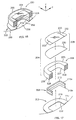
- FIG. 15 A first preferred embodiment of our invention is illustrated in Figs. 16-18, a second embodiment is illustrated in Figs. 19-21A, B and C and a third embodiment is illustrated in Figs. 22-24.
- identical reference numerals specify identical parts throughout the drawings.
- the wound cover 205 includes a layer 230 preferably of 4 mil.-thick clear, flexible polyurethane film with favorable characteristics selected, but not limited, to include moisture vapor transfer, oxygen permeability, and transmission of infrared radiation. Such material is available as a product sold under the name Deerfield 6100S.
- the layer 230 is attached to the upper surface 225 of the support member 206 by a ring of adhesive (not shown) comprising a synthetic rubber-based adhesive such as the product sold under the trade name HL-2306-X by H.B. Fuller Adhesive.
- a ring of adhesive comprising a synthetic rubber-based adhesive such as the product sold under the trade name HL-2306-X by H.B. Fuller Adhesive.
- the wound cover 205 further includes a stretcher layer 232 attached to the layer 230 so that the layer 230 is sandwiched between the stretcher layer 232 and the upper surface 225 of the standoff 206.
- the stretcher layer 232 is preferably a 5 mil.-thick planar sheet of (preferably) clear, somewhat flexible polyester film having enough stiffness to aid in maintaining planarity of the wound treatment portion 204.
- the function of the stretcher layer 232 is to hold the layer 230 taut, much as a "stretcher frame" tautens an artist's canvas.
- the stretcher layer 232 is attached to the layer 230 by a layer of adhesive (not shown) comprising a clear flexible polyester carrier film coated on both sides with an aggressive adhesive.
- the stretcher layer 232 further includes a pair of slits 233 that receive a detachable heater. With the provision of the slits 233, a pocket is formed between the stretcher layer 232 and the layer 230.
- first and second embodiments of the transition portion 208 are illustrated. It is understood that these embodiments are only representative of the general principle of providing a joint between the attachment portion 202 and the wound treatment portion 204 that acts between the bottom surface of the standoff 206 and the top surface 219 of the attachment portion 202.
- Figs. 16, 17, 19 and 20 are cross-sectional perspective views of the first and second embodiments taken along lines A-A of Fig. 15.
- the pleated member 210 is preferably attached to the upper surface 219 of the attachment portion 202 near the inner perimeter 222. This is shown clearly in Figs. 16 and 18. Nevertheless, the pleated member 210 could be dimensioned to be attached between the attachment and wound treatment portions 202 and 204 along any closed-looped trace between the lower surface of the standoff 206 and the upper surface 219 of the attachment portion 204.
- the pleated member comprises a urethane film which may be molded or extruded to form the multiple stacked pleats shown in the figures.
- the flexible, non-contact wound treatment device 200 with a transition portion 208 in the first embodiment in the form of a pleated member 210 is suitable for placement onto a skin surface 250 so as to surround a selected wound area 252 that abuts a treatment volume 256 enclosed or contained within the wound treatment device 200.
- This attachment may be directly to the skin surface 250, or on another member such as an ostomy ring that is, in turn, mounted or attached to the skin surface 250.
- the flexible, non-contact wound treatment device 200 of this invention satisfies the objective previously stated by a capability of being conformably attached to an uneven, changing surface supporting a wound treatment portion 204 that remains reasonably or substantially in its original shape, regardless of body contour or movements.
- the attachment portion 202 operates as a flexion joint that flexes to adapt to the contour of the skin surface 252.
- the transition portion 208 in the form of the pleated member 210 supports relative movement between the attachment and wound treatment portions 202 and 204, permitting them to move toward and away from each other, and also parallel to each other, thereby enhancing the conformability of the wound treatment device 200 to contour and movement of the body.
- the attachment portion 202 is free to conform to the shape of the skin surface 250 by flexibly deforming between the inner and outer perimeters 222 and 223.
- the wound treatment portion 204 is relatively undeformed so that the standoff 206 is able to support the layer 230 and stretcher 232 in a predetermined orientation with respect to the wound area 252.
- the wound treatment device 200 forms a barrier between the wound treatment volume 256 and the ambient atmosphere by virtue of the seal between the wound cover 205 and the standoff 206, the skinned outer and lower surfaces of the standoff 206, and the seals between the pleated member 210 and the standoff 206 and attachment portion 202.
- the bottom of the wound treatment device 200 is sealed to the skin 250 when the release layer (not shown) is peeled off so that the lower adhesive film layer (not shown) of the attachment portion 202 seals to the skin surface 250.
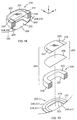
- the second embodiment of the transition portion 208 may be understood with reference to Figs. 19, 20 and 21A-21C.
- the transition portion comprises a seam acting between the lower surface of the standoff 206 and the upper surface 219 of the attachment portion 202.
- Three possible seam locations are shown in Fig. 20.
- Such a seam may be formed by any appropriate means of attachment between the attachment portion 202 and the lower surface of the standoff 206. Such may include, without limitation, adhesive attachment, heat bonding, or any other appropriate measure.
- a seam may be placed between other elements that effectively connect the seam to the attachment portion 202 and the lower surface of the standoff 206 in the location shown and for the purposes described.
- the second embodiment of the transition portion 208 effectively allows articulation between the attachment portion 202 and the wound treatment portion 204.
- This is shown clearly in Figs. 19 and 21A-21C.
- the seal is in the location indicated by 208/220 in Fig. 20, essentially sealing an outer periphery of the upper surface 219 near the outer perimeter 223 to a corresponding outer periphery of the lower surface of the standoff 206.
- This permits the section of the attachment portion 202 extending to the inner perimeter 222 to articulate toward or away from the lower surface of the stand off 206.
- FIG. 21A shows attachment of the attachment portion 202 along the seam 208/222 to the lower surface of the standoff 206 near the inner perimeter 222, where the section of the attachment portion 202 extending to the outer perimeter 223 can articulate toward or away from the lower surface of the standoff 206.
- Fig. 21C shows attachment of the upper surface 219 to the lower surface of the standoff 206 along the seam 208/221. In this location, the seam permits articulation of multiple sections of the attachment portion 202.
- the transition portion 208 may be understood with reference to Figs. 22-24.
- the transition portion comprises a bridge of foam material spanning and providing a narrow passage through the space between the bottom surface of the standoff 206 and the top surface 219 of the attachment portion 202.
- the bridge 209 is provided during the manufacture of the standoff 206 and the attachment portion 202 as an integrated, unitary piece by, for example, molding open-celled plastic foam of the self-skinning type. In this case, the bridge 209 is provided for in the mold and forms concurrently and integrally with the standoff 206 and the attachment portion 202.
- an adhesive film layer with an attached release liner 112, 113 may be attached to the lower surface of the attachment portion for application of the wound treatment device to a skin surface.
- the bridge 209 may be selectively located between the inner and outer perimeters 222 and 223 of the attachment portion 202 as with the first and second embodiments described above.
- the wound treatment device of Figs. 22-24 is substantially identical with the wound treatment devices in Figs. 15-21C.
- the bridge 209 effectively allows articulation between the attachment portion 202 and the wound treatment portion 204.
- the shapes and extents of the bottom surface of the standoff 206 and the attachment portion 202 align and largely overlap, thereby reducing the "footprint" of the wound treatment device 200 to a single, substantially annular shape (which may be many-sided or circular), from the concentric shapes of Figs, 2 and 3.
- the joint acting between the lower surface of the standoff 206 and the upper surface 219 ofthe attachment portion 202 increases conformability ofthe wound treatment device 200 to shape and movement, while maintaining the predetermined shape of the wound cover 205 and preventing its contact with the wound.
Landscapes
- Health & Medical Sciences (AREA)
- Public Health (AREA)
- Veterinary Medicine (AREA)
- Heart & Thoracic Surgery (AREA)
- Vascular Medicine (AREA)
- Life Sciences & Earth Sciences (AREA)
- Animal Behavior & Ethology (AREA)
- General Health & Medical Sciences (AREA)
- Engineering & Computer Science (AREA)
- Biomedical Technology (AREA)
- Epidemiology (AREA)
- Materials For Medical Uses (AREA)
- Surgical Instruments (AREA)
- Catching Or Destruction (AREA)
- Massaging Devices (AREA)
- Media Introduction/Drainage Providing Device (AREA)
- Orthopedics, Nursing, And Contraception (AREA)
- Invalid Beds And Related Equipment (AREA)
Claims (21)
- Berührungsfreie Wundbehandlungsvorrichtung (22) mit einem Abstandselement (206), das ein Behandlungs-Volumen (256) definiert, einem flexiblen Befestigungsbereich (202) mit einer oberen Oberfläche (219), und mit einer Schicht (230) über einer oberen Oberfläche (225) des Abstandselements, dadurch gekennzeichnet, dass
das Abstandselement flexibel ist;
das Abstandselement eine untere Oberfläche (207) hat, die an einem inneren Umfang bzw. Begrenzung (228) der unteren Oberfläche in eine absorbierende innere Oberfläche (227) übergeht, und
ein Übergangsbereich (208), der eine flexible Verbindung (210, 208/220, 209) unter und unterhalb der unteren Oberfläche des Abstandselementes enthält und die untere Oberfläche mit der oberen Oberfläche des Befestigungsbereiches verbindet. - Berührungsfreie Wundebehandlungsvorrichtung nach Anspruch 1, wobei der Übergangsbereich ein gefaltetes bzw. plissiertes Element (210) ist.
- Berührungsfreie Wundbehandlungsvorrichtung nach Anspruch 2, wobei das gefaltete Element (2) mehrere, aufeinandergestapelte Falten bzw. Plissees hat.
- Berührungsfreie Wundbehandlungsvorrichtung nach Anspruch 2, wobei das gefaltete Element (210) an der inneren Begrenzung (228) an dem Abstandselement (226) und an dem inneren Umfang bzw. Begrenzung (222) an der oberen Oberfläche (219) befestigt ist.
- Berührungsfreie Wundbehandlungsvorrichtung nach Anspruch 2, wobei das gefaltete Element (210) an einem äußeren Umfang bzw. Begrenzung der unteren Oberfläche an dem Abstandselement (206) befestigt ist, wo das Abstandselement in die äußere Oberfläche (226) übergeht, und mit der oberen Oberfläche (219) an einem äußeren Umfang bzw. Begrenzung (223) der oberen Oberfläche befestigt ist.
- Berührungsfreie Wundbehandlungsvorrichtung nach Anspruch 2, wobei das plissierte Element eine Urethan-Film ist.
- Berührungsfreie Wundbehandlungsvorrichtung nach Anspruch 1, wobei der Übergangsbereich eine Naht (208, 220) ist, die zwischen dem inneren und dem äußeren Umfang bzw. Begrenzung der oberen Oberfläche (219) des Befestigungsbereiches angeordnet ist.
- Berührungsfreie Wundbehandlungsvorrichtung nach Anspruch 1, wobei der Übergangsbereich eine Naht (208, 221) ist, die zwischen dem inneren und äußeren Umfang bzw. Begrenzung der oberen Oberfläche (219) des Befestigungsbereichs angeordnet ist.
- Berührungsfreie Wundbehandlungsvorrichtung nach Anspruch 1, wobei der Übergangsbereich eine Naht (208, 222) ist, die zwischen dem inneren und dem äußeren Umfang bzw. Begrenzung der oberen Oberfläche (219) des Befestigungsbereichs angeordnet ist.
- Berührungsfreie Wundbehandlungsvorrichtung nach Anspruch 1, wobei der Übergangsbereich eine schmale Material-Brücke (209) ist, die zwischen dem inneren und dem äußeren Umfang bzw. Begrenzung der oberen Oberfläche (219) des Befestigungsbereiches angeordnet ist.
- Berührungsfreie Wundbehandlungsvorrichtung nach Anspruch 10, wobei die Brücke (209) an dem inneren Umfang bzw. Begrenzung (223) der oberen Oberfläche (219) und dem entsprechenden äußeren Umfang bzw. Begrenzung der unteren Oberfläche (207) des Abstandselementes (206) längs einer Naht (208, 220) angeordnet ist.
- Berührungsfreie Wundbehandlungsvorrichtung nach Anspruch 10, wobei die Brücke (210) an dem inneren Umfang (222) der oberen Oberfläche (219) und dem entsprechenden inneren Umfang bzw. Begrenzung (228) der unteren Oberfläche (207) des Abstandselementes (206) längs einer Naht (208, 222) angeordnet ist.
- Berührungsfreie Wundbehandlungsvorrichtung nach Anspruch 1, wobei die Brücke (209) an dem äußeren Umfang bzw. Begrenzung der oberen Oberfläche (219) und dem entsprechenden inneren Umfang bzw. Begrenzung (228) der unteren Oberfläche (207) des Abstandselementes (206) längs einer Naht (208, 221) angeordnet ist.
- Berührungsfreie Wundbehandlungsvorrichtung nach Anspruch 1, wobei die Schicht (230) ein flexibler Polyurethan-Film ist.
- Berührungsfreie Wundbehandlungsvorrichtung nach Anspruch 14, wobei der Film eine oder mehrere Charakteristiken bzw. Eigenschaften hat, die aus der Gruppe Feuchtigkeitsdarnpf-Übertragung bzw. -Durchlässigkeit, Sauerstoff-Durchlässigkeit und Transmission für Infrarot-Strahlung ausgewählt ist bzw. sind.
- Berührungsfreie Wundbehandlungsvorrichtung nach Anspruch 1, wobei die Wundbehandlungsvorrichtung (220) eine Strecker- bzw. Spreizer-Schicht (223) hat, die in der Weise an der Schicht (230) befestigt ist, dass die Schicht (230) sandwichartig zwischen der Spreizer-Schicht (232) und der oberen Oberfläche (225) des Abstandselementes (206) angeordnet ist.
- Berührungsfreie Wundbehandlungsvorrichtung nach Anspruch 16, wobei die Spreizer-Schicht (232) ein planares Flächengebilde bzw. Blatt aus einem Polyester-Film mit einer geringeren Flexibilität als die Schicht (230) ist.
- Berührungsfreie Wundbehandlungsvorrichtung nach Anspruch 15, wobei sowohl die Spreizer-Schicht (232) als auch die Schicht (230) klar bzw. durchsichtig sind.
- Berührungsfreie Wundbehandlungsvorrichtung nach den Ansprüchen 1 bis 18, wobei das Abstandselement ein Ring aus einem fluiden, absorbierenden Schaum-Material ist.
- Berührungsfreie Wundbehandlungsvorrichtung nach Anspruch 19, wobei die obere Oberfläche (225), die äußere Oberfläche (226) und die untere Oberfläche (207) des Abstandselementes (206) undurchdringlich für fluide Medien sind.
- Berührungsfreie Wundbehandlungsvorrichtung nach Anspruch 19, wobei die innere Oberfläche (227) und die äußere Oberfläche (226) des Abstandselementes (206) durchlässig für fluide Medien sind, während die obere Oberfläche (225) und die untere Oberfläche (207) des Abstandselements (206) undurchlässig für fluide Medien sind.
Applications Claiming Priority (3)
| Application Number | Priority Date | Filing Date | Title |
|---|---|---|---|
| US08/843,072 US6110197A (en) | 1994-11-21 | 1997-04-11 | Flexible non-contact wound treatment device with a single joint |
| US843072 | 1997-04-11 | ||
| PCT/US1998/000344 WO1998046178A1 (en) | 1997-04-11 | 1998-01-14 | Flexible non-contact wound treatment device with a single joint |
Publications (2)
| Publication Number | Publication Date |
|---|---|
| EP0973469A1 EP0973469A1 (de) | 2000-01-26 |
| EP0973469B1 true EP0973469B1 (de) | 2001-10-17 |
Family
ID=25289016
Family Applications (1)
| Application Number | Title | Priority Date | Filing Date |
|---|---|---|---|
| EP98902779A Expired - Lifetime EP0973469B1 (de) | 1997-04-11 | 1998-01-14 | Flexible, berührungsfreie wundbehandlungsvorrichtung mit einer einfachen verbindung |
Country Status (7)
| Country | Link |
|---|---|
| US (2) | US6110197A (de) |
| EP (1) | EP0973469B1 (de) |
| AT (1) | ATE206904T1 (de) |
| AU (1) | AU728764B2 (de) |
| CA (1) | CA2284166C (de) |
| DE (1) | DE69802075T2 (de) |
| WO (1) | WO1998046178A1 (de) |
Families Citing this family (79)
| Publication number | Priority date | Publication date | Assignee | Title |
|---|---|---|---|---|
| US7928281B2 (en) | 1992-06-19 | 2011-04-19 | Arizant Technologies Llc | Wound covering |
| US6110197A (en) * | 1994-11-21 | 2000-08-29 | Augustine Medical, Inc. | Flexible non-contact wound treatment device with a single joint |
| US6093160A (en) * | 1994-11-21 | 2000-07-25 | Augustine Medical, Inc. | Flexible non-contact wound treatment device |
| US5817145A (en) * | 1994-11-21 | 1998-10-06 | Augustine Medical, Inc. | Wound treatment device |
| US6071304A (en) | 1998-04-06 | 2000-06-06 | Augustine Medical, Inc. | Wound treatment apparatus with a heater adhesively joined to a bandage |
| US6458109B1 (en) | 1998-08-07 | 2002-10-01 | Hill-Rom Services, Inc. | Wound treatment apparatus |
| EP1233808B1 (de) | 1999-11-29 | 2008-07-09 | Hill-Rom Services, Inc. | Vorrichtung zur behandlung einer wunde |
| US6764462B2 (en) | 2000-11-29 | 2004-07-20 | Hill-Rom Services Inc. | Wound treatment apparatus |
| US6824533B2 (en) | 2000-11-29 | 2004-11-30 | Hill-Rom Services, Inc. | Wound treatment apparatus |
| US6528697B1 (en) | 2000-01-03 | 2003-03-04 | Augustine Medical, Inc. | Modular bandage |
| DE60135746D1 (de) | 2000-05-22 | 2008-10-23 | Arthur C Coffey | Wundverband mit sis-schicht und vakuumkammer |
| US6855135B2 (en) | 2000-11-29 | 2005-02-15 | Hill-Rom Services, Inc. | Vacuum therapy and cleansing dressing for wounds |
| US6685681B2 (en) | 2000-11-29 | 2004-02-03 | Hill-Rom Services, Inc. | Vacuum therapy and cleansing dressing for wounds |
| US7732656B2 (en) * | 2001-05-10 | 2010-06-08 | Arizant Healthcare Inc. | Minimal contact treatment device |
| CA2451774A1 (en) | 2001-07-12 | 2003-01-23 | Robert Petrosenko | Control of vacuum level rate of change |
| US20030093041A1 (en) | 2001-10-11 | 2003-05-15 | Risk James R. | Waste container for negative pressure therapy |
| AU2002359829A1 (en) | 2001-12-26 | 2003-07-24 | Hill-Rom Services, Inc. | Vacuum bandage packing |
| US7195624B2 (en) | 2001-12-26 | 2007-03-27 | Hill-Rom Services, Inc. | Vented vacuum bandage with irrigation for wound healing and method |
| US7723560B2 (en) | 2001-12-26 | 2010-05-25 | Lockwood Jeffrey S | Wound vacuum therapy dressing kit |
| WO2003073970A1 (en) | 2002-02-28 | 2003-09-12 | Hill-Rom Services, Inc. | External catheter access to vacuum bandage |
| US8168848B2 (en) | 2002-04-10 | 2012-05-01 | KCI Medical Resources, Inc. | Access openings in vacuum bandage |
| EP3181178B1 (de) | 2002-08-21 | 2019-01-30 | KCI Medical Resources | Wundverpackung zur verhinderung des wundverschlusses |
| GB0224986D0 (en) | 2002-10-28 | 2002-12-04 | Smith & Nephew | Apparatus |
| US7265256B2 (en) * | 2003-01-17 | 2007-09-04 | Ther Memorial Hospital | Bandaging device for sequestering a wound or inoculation site |
| GB0325129D0 (en) | 2003-10-28 | 2003-12-03 | Smith & Nephew | Apparatus in situ |
| GB0325126D0 (en) | 2003-10-28 | 2003-12-03 | Smith & Nephew | Apparatus with heat |
| US7776028B2 (en) | 2004-04-05 | 2010-08-17 | Bluesky Medical Group Incorporated | Adjustable overlay reduced pressure wound treatment system |
| US10058642B2 (en) | 2004-04-05 | 2018-08-28 | Bluesky Medical Group Incorporated | Reduced pressure treatment system |
| US7909805B2 (en) | 2004-04-05 | 2011-03-22 | Bluesky Medical Group Incorporated | Flexible reduced pressure treatment appliance |
| US7708724B2 (en) | 2004-04-05 | 2010-05-04 | Blue Sky Medical Group Incorporated | Reduced pressure wound cupping treatment system |
| US8062272B2 (en) | 2004-05-21 | 2011-11-22 | Bluesky Medical Group Incorporated | Flexible reduced pressure treatment appliance |
| GB0409444D0 (en) * | 2004-04-28 | 2004-06-02 | Smith & Nephew | Apparatus |
| GB0409446D0 (en) | 2004-04-28 | 2004-06-02 | Smith & Nephew | Apparatus |
| US8529548B2 (en) | 2004-04-27 | 2013-09-10 | Smith & Nephew Plc | Wound treatment apparatus and method |
| WO2006086513A2 (en) | 2005-02-08 | 2006-08-17 | Carewave, Inc. | Apparatus and method for using a portable thermal device to reduce accommodation of nerve receptors |
| US7745683B2 (en) * | 2005-04-16 | 2010-06-29 | Aalnex, Inc. | Deformable and conformable wound protecting apparatus and its method of application |
| US8415523B2 (en) * | 2005-04-16 | 2013-04-09 | Aalnex, Inc. | Secondary wound dressings for securing primary dressings and managing fluid from wounds, and methods of using same |
| US8067662B2 (en) | 2009-04-01 | 2011-11-29 | Aalnex, Inc. | Systems and methods for wound protection and exudate management |
| CN101180015B (zh) * | 2005-05-20 | 2012-05-30 | 科洛普拉斯特公司 | 用于冲洗和/或排泄的装置 |
| EP1922045B1 (de) | 2005-09-07 | 2012-11-07 | Tyco Healthcare Group LP | Abgeschlossener wundverband mit mikropumpe |
| US8586818B2 (en) * | 2005-12-15 | 2013-11-19 | Aalnex, Inc. | Wound shield |
| US7601129B2 (en) * | 2005-12-15 | 2009-10-13 | Aalnex, Inc. | Wound shield and warming apparatus and method |
| US7863495B2 (en) * | 2006-01-12 | 2011-01-04 | Aalnex, Inc. | Dressing substrate |
| US7816577B2 (en) * | 2006-02-13 | 2010-10-19 | Aalnex, Inc. | Wound shield |
| US7779625B2 (en) | 2006-05-11 | 2010-08-24 | Kalypto Medical, Inc. | Device and method for wound therapy |
| EP2990064B1 (de) | 2006-10-17 | 2024-04-10 | Smith & Nephew plc | Hilfsangetriebene negativdruck-wundtherapie-vorrichtungen |
| US7931651B2 (en) | 2006-11-17 | 2011-04-26 | Wake Lake University Health Sciences | External fixation assembly and method of use |
| US8377016B2 (en) | 2007-01-10 | 2013-02-19 | Wake Forest University Health Sciences | Apparatus and method for wound treatment employing periodic sub-atmospheric pressure |
| US8191550B2 (en) * | 2007-05-24 | 2012-06-05 | Embrace, Llc | Method and apparatus to relieve menstrual pain |
| US20080289623A1 (en) * | 2007-05-24 | 2008-11-27 | Lee Stephen D | Therapeutic compression belt |
| US10149780B2 (en) * | 2007-05-24 | 2018-12-11 | Ziivaa Ip, Llc | Compression undergarment for relief of menstrual pain and related method of use |
| US9107753B2 (en) | 2007-05-24 | 2015-08-18 | Ziivaa Ip, Llc | Method to relieve menstrual pain |
| GB0712763D0 (en) * | 2007-07-02 | 2007-08-08 | Smith & Nephew | Apparatus |
| EP2205189B1 (de) | 2007-10-10 | 2017-12-06 | Wake Forest University Health Sciences | Vorrichtungen zur behandlung von rückenmarksgewebe |
| AU2008327660B2 (en) | 2007-11-21 | 2014-02-13 | Smith & Nephew Plc | Wound dressing |
| GB0722820D0 (en) | 2007-11-21 | 2008-01-02 | Smith & Nephew | Vacuum assisted wound dressing |
| CN101868203B (zh) | 2007-11-21 | 2014-10-22 | 史密夫及内修公开有限公司 | 伤口包敷物 |
| ES2555204T3 (es) * | 2007-11-21 | 2015-12-29 | T.J. Smith & Nephew Limited | Dispositivo de succión y venda |
| US8579953B1 (en) | 2007-12-07 | 2013-11-12 | Peter J. Dunbar | Devices and methods for therapeutic heat treatment |
| RU2517588C2 (ru) | 2008-01-09 | 2014-05-27 | Уэйк Форест Юниверсити Хелс Сайенсиз | Устройство и способ лечения патологий центральной нервной системы |
| KR20110070976A (ko) | 2008-07-18 | 2011-06-27 | 웨이크 포리스트 유니버시티 헬스 사이언시즈 | 세포 사멸 및 세포 손상을 최소화하기 위해 국부적 진공 적용에 의해 심장 조직을 변조하기 위한 장치 및 방법 |
| GB0814102D0 (en) * | 2008-08-01 | 2008-09-10 | Cambridge University Hospitals | Tracheostomy dressing |
| US8663198B2 (en) | 2009-04-17 | 2014-03-04 | Kalypto Medical, Inc. | Negative pressure wound therapy device |
| US8252971B2 (en) * | 2009-07-16 | 2012-08-28 | Aalnex, Inc. | Systems and methods for protecting incisions |
| KR101949543B1 (ko) | 2011-01-21 | 2019-02-18 | 케어웨이브 메디컬, 인크. | 모듈형 자극 인가 시스템 및 방법 |
| US20120277648A1 (en) * | 2011-04-28 | 2012-11-01 | Tianna Michelle Kendall | Adhesive bandage with raised portion |
| US9058634B2 (en) | 2011-05-24 | 2015-06-16 | Kalypto Medical, Inc. | Method for providing a negative pressure wound therapy pump device |
| WO2012161723A1 (en) | 2011-05-24 | 2012-11-29 | Kalypto Medical, Inc. | Device with controller and pump modules for providing negative pressure for wound therapy |
| US9067003B2 (en) | 2011-05-26 | 2015-06-30 | Kalypto Medical, Inc. | Method for providing negative pressure to a negative pressure wound therapy bandage |
| AU2012288823B2 (en) * | 2011-07-28 | 2016-11-10 | Hollister Incorporated | An ostomy sealing member package and an ostomy sealing member therefore |
| CN103889378B (zh) | 2011-11-15 | 2016-08-17 | 凯希特许有限公司 | 具有热增强的蒸汽传输的医用敷件、系统、以及方法 |
| US10596041B2 (en) | 2014-08-28 | 2020-03-24 | Ascension Texas | Apparatuses and methods for minimizing wound dehiscence, scar spread, and/or the like |
| US10583228B2 (en) | 2015-07-28 | 2020-03-10 | J&M Shuler Medical, Inc. | Sub-atmospheric wound therapy systems and methods |
| USD848608S1 (en) | 2016-10-21 | 2019-05-14 | Coloplast A/S | Base unit for anal irrigation and controller |
| EA202091381A1 (ru) | 2017-12-20 | 2020-08-24 | Фармадом С.Р.Л. | Жесткий или полужесткий защитный элемент для покрытия ран |
| EP3761925A4 (de) | 2018-03-07 | 2021-12-08 | Soovu Labs, Inc. | Systeme und verfahren für verbesserte schmerzlinderung aus der stimulation von thermischen fasern |
| US11160917B2 (en) | 2020-01-22 | 2021-11-02 | J&M Shuler Medical Inc. | Negative pressure wound therapy barrier |
| JP2022106461A (ja) * | 2021-01-07 | 2022-07-20 | 花王株式会社 | 身体貼付用シート |
| USD1014764S1 (en) * | 2021-11-16 | 2024-02-13 | Raymond Lovell Francis | Skin-attachable block set that provides no-touch protection for skin insults |
Family Cites Families (87)
| Publication number | Priority date | Publication date | Assignee | Title |
|---|---|---|---|---|
| US222690A (en) * | 1879-12-16 | Improvement in surgical bandages | ||
| US720812A (en) * | 1901-01-12 | 1903-02-17 | Robert W Johnson | Vaccination-shield. |
| US697637A (en) * | 1901-11-12 | 1902-04-15 | John Ellwood Lee | Shield for vaccinations, &c. |
| GB190203090A (en) * | 1902-02-07 | 1902-06-25 | William Hugh Alexander | Improvements in Shields for Protecting Corns, Bunions, or Vaccination Spots. |
| US1399095A (en) * | 1919-12-02 | 1921-12-06 | Sr Jean F Webb | Vacuo-thermic-body-treatment appliance |
| US1384467A (en) * | 1920-01-27 | 1921-07-12 | Electrothermal Company | Bandage |
| GB288220A (en) * | 1927-04-09 | 1928-08-23 | David Sarason | Dressing-ring |
| US1777982A (en) * | 1928-02-20 | 1930-10-07 | Popp Karl | Hot-air mat |
| US1920808A (en) * | 1929-05-10 | 1933-08-01 | Sander Eugen | Surgical bandaging |
| US1979082A (en) * | 1932-04-21 | 1934-10-30 | Gen Electric | Electric heater |
| US2221758A (en) * | 1937-05-12 | 1940-11-19 | Elmquist Francis | Surgical dressing |
| US2443481A (en) * | 1942-10-19 | 1948-06-15 | Sene Leon Paul | Device for the treatment of wounds and the like lesions |
| CH269938A (fr) * | 1944-12-11 | 1950-07-31 | Serra Balaguer Jose | Dispositif isolant pour abcès, vaccins et autres affections ou lésions cutanées. |
| US2573791A (en) * | 1947-04-19 | 1951-11-06 | John N M Howells | Heat applying bandage |
| US2577945A (en) * | 1947-12-06 | 1951-12-11 | Atherton Harold Starr | Plaster or bandage for skin application |
| US2632443A (en) * | 1949-04-18 | 1953-03-24 | Eleanor P Lesher | Surgical dressing |
| US2599523A (en) * | 1949-07-27 | 1952-06-03 | Dorr Emma Ashton | Shield for bunions and corns |
| US2601189A (en) * | 1949-08-22 | 1952-06-17 | Theodore Backer | Air comforter bed covering |
| US2706988A (en) * | 1951-11-19 | 1955-04-26 | Jarolux A G | Human body heat treating apparatus |
| US2769892A (en) * | 1953-05-04 | 1956-11-06 | Donald F Collins | Electrical heating device |
| US2918062A (en) * | 1958-07-30 | 1959-12-22 | William M Scholl | Medicinal plaster or bandage |
| US3026874A (en) * | 1959-11-06 | 1962-03-27 | Robert C Stevens | Wound shield |
| FR1303238A (fr) * | 1961-09-07 | 1962-09-07 | Pansement | |
| FR1489127A (fr) * | 1966-06-06 | 1967-07-21 | Anne Marie Janny | Pansement perfectionné |
| FR1527887A (fr) * | 1967-03-14 | 1968-06-07 | Perfectionnements apportés aux pansements protecteurs et aux protecteurs de pansements | |
| US3528416A (en) * | 1967-11-06 | 1970-09-15 | Lawrence J Chamberlain | Protective bandage |
| GB1258567A (de) * | 1968-07-25 | 1971-12-30 | ||
| US3596657A (en) * | 1969-02-14 | 1971-08-03 | William Eidus | Thermally conductive surgical dressing |
| DE1956683C3 (de) * | 1969-11-11 | 1973-12-20 | Schneeberger Kork Ag, Dulliken (Schweiz) | Elastische Druckbandage für die Wärmebehandlung von Körperteilen und Verfahren zu deren Herstellung |
| US3610238A (en) * | 1970-04-28 | 1971-10-05 | Us Health Education & Welfare | Wound infection prevention device |
| US3691646A (en) * | 1971-01-22 | 1972-09-19 | Hector Michael Ruffolo | Hair dryer |
| US3782377A (en) * | 1971-09-07 | 1974-01-01 | Illinois Tool Works | Sterile plastic shield |
| US3814095A (en) * | 1972-03-24 | 1974-06-04 | H Lubens | Occlusively applied anesthetic patch |
| US3867939A (en) * | 1972-05-18 | 1975-02-25 | Moore Perk Corp | Disposable, sterile temperature control applicator pad for medical application |
| US3881477A (en) * | 1973-08-07 | 1975-05-06 | Nichols Henry E | Fluid discharge appliance for maintaining a sterile enclosure |
| US4080971A (en) * | 1976-07-30 | 1978-03-28 | Rory Ann Leeper | Battery powered foot warming insole |
| US4134399A (en) * | 1977-06-13 | 1979-01-16 | Alfred Halderson | Skin protective device |
| US4172495A (en) * | 1977-08-03 | 1979-10-30 | Energy Systems Corporation | Slurry cooling of helmets |
| GB2047543B (en) * | 1978-12-06 | 1983-04-20 | Svedman Paul | Device for treating tissues for example skin |
| US4279255A (en) * | 1980-02-26 | 1981-07-21 | John F. Taylor | Localized body heat applicator device |
| US4399816A (en) * | 1980-03-17 | 1983-08-23 | Spangler George M | Wound protector with transparent cover |
| GB2082919A (en) * | 1980-09-04 | 1982-03-17 | Jones Leslie Bernard | Wound dressings |
| US4341209A (en) * | 1981-01-12 | 1982-07-27 | The Kendall Company | Adhesive bandage with foam backing |
| DE3102674A1 (de) * | 1981-01-28 | 1982-09-02 | Walter Dr.-Ing. 5100 Aachen Jürgens | Verbandmaterial |
| DE3118232A1 (de) * | 1981-05-08 | 1982-11-18 | Hestia Pharma GmbH, 6800 Mannheim | Hautverband |
| US4468227A (en) * | 1981-05-29 | 1984-08-28 | Hollister Incorporated | Wound drainage device with resealable access cap |
| US4517972A (en) * | 1983-01-11 | 1985-05-21 | Finch Jr Robert E | Method and apparatus for applying a therapeutic article to a body |
| DE8305103U1 (de) * | 1983-02-24 | 1988-04-28 | Schelowsky, Michael, 4790 Paderborn | Hohlraumbildender Wundverband zur ambulanten Behandlung des Wundraumklimas - Wundraumklima-Verband |
| SU1174028A1 (ru) * | 1983-04-15 | 1985-08-23 | Институт Хирургии Им.А.В.Вишневского | Способ лечени ожоговых ран @ степени II-III (его варианты) и устройство дл его осуществлени |
| US4540412A (en) * | 1983-07-14 | 1985-09-10 | The Kendall Company | Device for moist heat therapy |
| US4778446A (en) * | 1983-07-14 | 1988-10-18 | Squibb & Sons Inc | Wound irrigation and/or drainage device |
| US4484574A (en) * | 1984-01-25 | 1984-11-27 | Keene Corporation | Self-rolled foam tape without release layer and method of making same |
| US4572188A (en) * | 1984-03-05 | 1986-02-25 | Augustine Scott D | Airflow cover for controlling body temperature |
| GB2176402B (en) * | 1985-06-20 | 1989-04-19 | Craig Med Prod Ltd | Wound management appliance for use on the human skin |
| US4641641A (en) * | 1985-09-13 | 1987-02-10 | Strock Alvin E | Protective appliance for the hip joint area |
| US4633863A (en) * | 1985-09-27 | 1987-01-06 | Filips Chester P | Arterial anchor bandage |
| US4628930A (en) * | 1985-10-24 | 1986-12-16 | Williams Steven N | Soothing comfort girdle |
| DE3539533A1 (de) * | 1985-11-07 | 1987-05-14 | Liedtke Pharmed Gmbh | Kunststoffpflaster |
| US4667666A (en) * | 1986-04-18 | 1987-05-26 | Alice Fryslie | Protective bandaging device |
| US4641643A (en) * | 1986-04-28 | 1987-02-10 | Greer Leland H | Resealing skin bandage |
| GB8700150D0 (en) * | 1987-01-06 | 1987-02-11 | Martin I F | Wound dressings |
| US4962761A (en) * | 1987-02-24 | 1990-10-16 | Golden Theodore A | Thermal bandage |
| IT8748594A0 (it) * | 1987-11-09 | 1987-11-09 | Checconi Pietro E Matteucci Do | Cerotto per medicazione a distanziatore incorporato |
| US5003971A (en) * | 1988-09-02 | 1991-04-02 | Buckley John T | Expansion system for a medical and surgical dressing |
| US5144113A (en) * | 1988-11-30 | 1992-09-01 | Safeway Products, Inc. | Electrically heated deicer for aircraft blades |
| US5144958A (en) * | 1989-06-28 | 1992-09-08 | Mobil Oil Corporation | Apparatus for conducting mammalian dermatological studies |
| US5106629A (en) * | 1989-10-20 | 1992-04-21 | Ndm Acquisition Corp. | Transparent hydrogel wound dressing |
| US4969881A (en) * | 1989-11-06 | 1990-11-13 | Connecticut Artcraft Corp. | Disposable hyperbaric oxygen dressing |
| US5025777A (en) * | 1989-11-09 | 1991-06-25 | Karen Worchell | Chemically heated blanket |
| US5609619A (en) * | 1990-02-13 | 1997-03-11 | Exergen Corporation | Method and apparatus for heating bodies |
| US5060662A (en) * | 1990-07-06 | 1991-10-29 | Farnswoth Iii Kenneth F | Open air bandage |
| US5086763A (en) * | 1990-08-06 | 1992-02-11 | Hathman Johnnie L | Protective reclosable wound dressing |
| US5135518A (en) * | 1990-08-28 | 1992-08-04 | Barbara Vera | Heat-retentive wet compress |
| EP0485657A1 (de) * | 1990-11-15 | 1992-05-20 | Catalina Biomedical Corporation | Modifizierbarer semipermeabler Wundverband |
| US5190031A (en) * | 1991-03-11 | 1993-03-02 | Raul Guibert | Universal thermotherapy applicator |
| US5107832A (en) * | 1991-03-11 | 1992-04-28 | Raul Guibert | Universal thermotherapy applicator |
| US5230350A (en) * | 1991-05-29 | 1993-07-27 | Tabex Industries, Inc. | Moisture barrier for indwelling catheters and the like |
| US5170781A (en) * | 1991-11-15 | 1992-12-15 | Loomis Dawn L | Protective bandage having improved impact protection |
| GB9125252D0 (en) * | 1991-11-27 | 1992-01-29 | Infra Therm Limited | Improvements in or relating to covers |
| CA2128209C (en) * | 1992-01-17 | 2001-04-10 | David W. Talbot | A heat conserving bandage |
| CA2138402C (en) * | 1992-06-19 | 2004-01-27 | Scott D. Augustine | Wound covering |
| PL172903B1 (pl) * | 1992-08-10 | 1997-12-31 | Okanagan House Inc | Bandaz termiczny PL PL PL PL PL |
| EP0607472B1 (de) * | 1993-01-09 | 1995-05-10 | Kabushiki Kaisha Advance | Auf die Haut zu befestigende elektrische Vorrichtung zur Wärmebehandlung |
| US5413587A (en) * | 1993-11-22 | 1995-05-09 | Hochstein; Peter A. | Infrared heating apparatus and methods |
| US6110197A (en) * | 1994-11-21 | 2000-08-29 | Augustine Medical, Inc. | Flexible non-contact wound treatment device with a single joint |
| US5817145A (en) * | 1994-11-21 | 1998-10-06 | Augustine Medical, Inc. | Wound treatment device |
| US5580346A (en) * | 1995-02-17 | 1996-12-03 | Spier; I. Martin | Protective covering for body lesions |
-
1997
- 1997-04-11 US US08/843,072 patent/US6110197A/en not_active Expired - Fee Related
-
1998
- 1998-01-14 DE DE69802075T patent/DE69802075T2/de not_active Expired - Lifetime
- 1998-01-14 AU AU59590/98A patent/AU728764B2/en not_active Ceased
- 1998-01-14 EP EP98902779A patent/EP0973469B1/de not_active Expired - Lifetime
- 1998-01-14 CA CA002284166A patent/CA2284166C/en not_active Expired - Fee Related
- 1998-01-14 AT AT98902779T patent/ATE206904T1/de not_active IP Right Cessation
- 1998-01-14 WO PCT/US1998/000344 patent/WO1998046178A1/en not_active Ceased
-
2000
- 2000-02-29 US US09/514,499 patent/US6267740B1/en not_active Expired - Lifetime
Also Published As
| Publication number | Publication date |
|---|---|
| WO1998046178A1 (en) | 1998-10-22 |
| ATE206904T1 (de) | 2001-11-15 |
| US6267740B1 (en) | 2001-07-31 |
| EP0973469A1 (de) | 2000-01-26 |
| CA2284166A1 (en) | 1998-10-22 |
| AU728764B2 (en) | 2001-01-18 |
| DE69802075T2 (de) | 2002-06-06 |
| AU5959098A (en) | 1998-11-11 |
| DE69802075D1 (de) | 2001-11-22 |
| CA2284166C (en) | 2004-12-14 |
| US6110197A (en) | 2000-08-29 |
Similar Documents
| Publication | Publication Date | Title |
|---|---|---|
| EP0973469B1 (de) | Flexible, berührungsfreie wundbehandlungsvorrichtung mit einer einfachen verbindung | |
| EP0973468B1 (de) | Flexible, berührungsfreie wundbehandlungsvorrichtung | |
| US5817145A (en) | Wound treatment device | |
| EP0645995B1 (de) | Wundabdeckung | |
| US5947914A (en) | Wound covering | |
| US7771377B2 (en) | Tissue treatment device for an extremity | |
| MXPA99008984A (en) | Flexible non-contact wound treatment device | |
| MXPA99008985A (en) | Flexible non-contact wound treatment device with a single joint | |
| HK1010330B (en) | Wound covering | |
| HK1010331A (en) | Wound covering | |
| HK1010329A (en) | Wound covering |
Legal Events
| Date | Code | Title | Description |
|---|---|---|---|
| PUAI | Public reference made under article 153(3) epc to a published international application that has entered the european phase |
Free format text: ORIGINAL CODE: 0009012 |
|
| 17P | Request for examination filed |
Effective date: 19990927 |
|
| AK | Designated contracting states |
Kind code of ref document: A1 Designated state(s): AT BE CH DE DK ES FI FR GB GR IE IT LI LU MC NL PT SE |
|
| 17Q | First examination report despatched |
Effective date: 20000713 |
|
| GRAG | Despatch of communication of intention to grant |
Free format text: ORIGINAL CODE: EPIDOS AGRA |
|
| GRAG | Despatch of communication of intention to grant |
Free format text: ORIGINAL CODE: EPIDOS AGRA |
|
| GRAH | Despatch of communication of intention to grant a patent |
Free format text: ORIGINAL CODE: EPIDOS IGRA |
|
| RAP1 | Party data changed (applicant data changed or rights of an application transferred) |
Owner name: AUGUSTINE MEDICAL, INC. |
|
| GRAH | Despatch of communication of intention to grant a patent |
Free format text: ORIGINAL CODE: EPIDOS IGRA |
|
| GRAA | (expected) grant |
Free format text: ORIGINAL CODE: 0009210 |
|
| AK | Designated contracting states |
Kind code of ref document: B1 Designated state(s): AT BE CH DE DK ES FI FR GB GR IE IT LI LU MC NL PT SE |
|
| PG25 | Lapsed in a contracting state [announced via postgrant information from national office to epo] |
Ref country code: NL Free format text: LAPSE BECAUSE OF FAILURE TO SUBMIT A TRANSLATION OF THE DESCRIPTION OR TO PAY THE FEE WITHIN THE PRESCRIBED TIME-LIMIT Effective date: 20011017 Ref country code: IT Free format text: LAPSE BECAUSE OF FAILURE TO SUBMIT A TRANSLATION OF THE DESCRIPTION OR TO PAY THE FEE WITHIN THE PRESCRIBED TIME-LIMIT;WARNING: LAPSES OF ITALIAN PATENTS WITH EFFECTIVE DATE BEFORE 2007 MAY HAVE OCCURRED AT ANY TIME BEFORE 2007. THE CORRECT EFFECTIVE DATE MAY BE DIFFERENT FROM THE ONE RECORDED. Effective date: 20011017 Ref country code: FI Free format text: LAPSE BECAUSE OF FAILURE TO SUBMIT A TRANSLATION OF THE DESCRIPTION OR TO PAY THE FEE WITHIN THE PRESCRIBED TIME-LIMIT Effective date: 20011017 Ref country code: AT Free format text: LAPSE BECAUSE OF FAILURE TO SUBMIT A TRANSLATION OF THE DESCRIPTION OR TO PAY THE FEE WITHIN THE PRESCRIBED TIME-LIMIT Effective date: 20011017 |
|
| REF | Corresponds to: |
Ref document number: 206904 Country of ref document: AT Date of ref document: 20011115 Kind code of ref document: T |
|
| REG | Reference to a national code |
Ref country code: CH Ref legal event code: EP |
|
| REG | Reference to a national code |
Ref country code: IE Ref legal event code: FG4D |
|
| REF | Corresponds to: |
Ref document number: 69802075 Country of ref document: DE Date of ref document: 20011122 |
|
| REG | Reference to a national code |
Ref country code: GB Ref legal event code: IF02 |
|
| PG25 | Lapsed in a contracting state [announced via postgrant information from national office to epo] |
Ref country code: LU Free format text: LAPSE BECAUSE OF NON-PAYMENT OF DUE FEES Effective date: 20020114 |
|
| PG25 | Lapsed in a contracting state [announced via postgrant information from national office to epo] |
Ref country code: SE Free format text: LAPSE BECAUSE OF FAILURE TO SUBMIT A TRANSLATION OF THE DESCRIPTION OR TO PAY THE FEE WITHIN THE PRESCRIBED TIME-LIMIT Effective date: 20020117 Ref country code: PT Free format text: LAPSE BECAUSE OF FAILURE TO SUBMIT A TRANSLATION OF THE DESCRIPTION OR TO PAY THE FEE WITHIN THE PRESCRIBED TIME-LIMIT Effective date: 20020117 Ref country code: DK Free format text: LAPSE BECAUSE OF FAILURE TO SUBMIT A TRANSLATION OF THE DESCRIPTION OR TO PAY THE FEE WITHIN THE PRESCRIBED TIME-LIMIT Effective date: 20020117 |
|
| PG25 | Lapsed in a contracting state [announced via postgrant information from national office to epo] |
Ref country code: GR Free format text: LAPSE BECAUSE OF FAILURE TO SUBMIT A TRANSLATION OF THE DESCRIPTION OR TO PAY THE FEE WITHIN THE PRESCRIBED TIME-LIMIT Effective date: 20020118 |
|
| ET | Fr: translation filed | ||
| REG | Reference to a national code |
Ref country code: CH Ref legal event code: NV Representative=s name: PATENTANWAELTE FELDMANN & PARTNER AG |
|
| NLV1 | Nl: lapsed or annulled due to failure to fulfill the requirements of art. 29p and 29m of the patents act | ||
| PG25 | Lapsed in a contracting state [announced via postgrant information from national office to epo] |
Ref country code: ES Free format text: LAPSE BECAUSE OF FAILURE TO SUBMIT A TRANSLATION OF THE DESCRIPTION OR TO PAY THE FEE WITHIN THE PRESCRIBED TIME-LIMIT Effective date: 20020430 |
|
| PLBE | No opposition filed within time limit |
Free format text: ORIGINAL CODE: 0009261 |
|
| STAA | Information on the status of an ep patent application or granted ep patent |
Free format text: STATUS: NO OPPOSITION FILED WITHIN TIME LIMIT |
|
| 26N | No opposition filed | ||
| REG | Reference to a national code |
Ref country code: CH Ref legal event code: PUE Owner name: ARIZANT HEALTHCARE INC. Free format text: AUGUSTINE MEDICAL, INC.#SUITE 100, 10393 WEST 70TH STREET#EDEN PRAIRIE, MN 55344 (US) -TRANSFER TO- ARIZANT HEALTHCARE INC.#SUITE 100, 10393 WEST 70TH STREET#EDEN PRAIRIE, MN 55344 (US) |
|
| REG | Reference to a national code |
Ref country code: GB Ref legal event code: 732E |
|
| REG | Reference to a national code |
Ref country code: CH Ref legal event code: NV Representative=s name: PATENTANWAELTE FELDMANN & PARTNER AG |
|
| REG | Reference to a national code |
Ref country code: FR Ref legal event code: TP |
|
| REG | Reference to a national code |
Ref country code: CH Ref legal event code: PFA Owner name: ARIZANT HEALTHCARE INC. Free format text: ARIZANT HEALTHCARE INC.#SUITE 100, 10393 WEST 70TH STREET#EDEN PRAIRIE, MN 55344 (US) -TRANSFER TO- ARIZANT HEALTHCARE INC.#SUITE 100, 10393 WEST 70TH STREET#EDEN PRAIRIE, MN 55344 (US) |
|
| PGFP | Annual fee paid to national office [announced via postgrant information from national office to epo] |
Ref country code: MC Payment date: 20101215 Year of fee payment: 14 Ref country code: IE Payment date: 20101216 Year of fee payment: 14 Ref country code: FR Payment date: 20101221 Year of fee payment: 14 |
|
| PGFP | Annual fee paid to national office [announced via postgrant information from national office to epo] |
Ref country code: CH Payment date: 20110103 Year of fee payment: 14 |
|
| PGFP | Annual fee paid to national office [announced via postgrant information from national office to epo] |
Ref country code: BE Payment date: 20110221 Year of fee payment: 14 |
|
| BERE | Be: lapsed |
Owner name: *ARIZANT HEALTHCARE INC. Effective date: 20120131 |
|
| PG25 | Lapsed in a contracting state [announced via postgrant information from national office to epo] |
Ref country code: MC Free format text: LAPSE BECAUSE OF NON-PAYMENT OF DUE FEES Effective date: 20120131 |
|
| REG | Reference to a national code |
Ref country code: CH Ref legal event code: PL |
|
| REG | Reference to a national code |
Ref country code: FR Ref legal event code: ST Effective date: 20120928 |
|
| REG | Reference to a national code |
Ref country code: IE Ref legal event code: MM4A |
|
| PG25 | Lapsed in a contracting state [announced via postgrant information from national office to epo] |
Ref country code: LI Free format text: LAPSE BECAUSE OF NON-PAYMENT OF DUE FEES Effective date: 20120131 Ref country code: CH Free format text: LAPSE BECAUSE OF NON-PAYMENT OF DUE FEES Effective date: 20120131 |
|
| PG25 | Lapsed in a contracting state [announced via postgrant information from national office to epo] |
Ref country code: FR Free format text: LAPSE BECAUSE OF NON-PAYMENT OF DUE FEES Effective date: 20120131 Ref country code: BE Free format text: LAPSE BECAUSE OF NON-PAYMENT OF DUE FEES Effective date: 20120131 |
|
| PG25 | Lapsed in a contracting state [announced via postgrant information from national office to epo] |
Ref country code: IE Free format text: LAPSE BECAUSE OF NON-PAYMENT OF DUE FEES Effective date: 20120114 |
|
| REG | Reference to a national code |
Ref country code: DE Ref legal event code: R082 Ref document number: 69802075 Country of ref document: DE Representative=s name: SCHWABE SANDMAIR MARX, DE |
|
| REG | Reference to a national code |
Ref country code: GB Ref legal event code: 732E Free format text: REGISTERED BETWEEN 20140220 AND 20140226 |
|
| REG | Reference to a national code |
Ref country code: DE Ref legal event code: R082 Ref document number: 69802075 Country of ref document: DE Representative=s name: SCHWABE SANDMAIR MARX, DE Effective date: 20140225 Ref country code: DE Ref legal event code: R081 Ref document number: 69802075 Country of ref document: DE Owner name: 3M INNOVATIVE PROPERTIES COMPANY, SAINT PAUL, US Free format text: FORMER OWNER: ARIZANT HEALTHCARE INC., EDEN PRAIRIE, MINN., US Effective date: 20140225 Ref country code: DE Ref legal event code: R081 Ref document number: 69802075 Country of ref document: DE Owner name: 3M INNOVATIVE PROPERTIES COMPANY, US Free format text: FORMER OWNER: ARIZANT HEALTHCARE INC., EDEN PRAIRIE, US Effective date: 20140225 |
|
| PGFP | Annual fee paid to national office [announced via postgrant information from national office to epo] |
Ref country code: DE Payment date: 20140108 Year of fee payment: 17 |
|
| PGFP | Annual fee paid to national office [announced via postgrant information from national office to epo] |
Ref country code: GB Payment date: 20140108 Year of fee payment: 17 |
|
| REG | Reference to a national code |
Ref country code: DE Ref legal event code: R119 Ref document number: 69802075 Country of ref document: DE |
|
| GBPC | Gb: european patent ceased through non-payment of renewal fee |
Effective date: 20150114 |
|
| PG25 | Lapsed in a contracting state [announced via postgrant information from national office to epo] |
Ref country code: GB Free format text: LAPSE BECAUSE OF NON-PAYMENT OF DUE FEES Effective date: 20150114 Ref country code: DE Free format text: LAPSE BECAUSE OF NON-PAYMENT OF DUE FEES Effective date: 20150801 |