EP0973030B1 - Methode zur Steuerung eines linearen Sauerstoffsensors - Google Patents
Methode zur Steuerung eines linearen Sauerstoffsensors Download PDFInfo
- Publication number
- EP0973030B1 EP0973030B1 EP99113851A EP99113851A EP0973030B1 EP 0973030 B1 EP0973030 B1 EP 0973030B1 EP 99113851 A EP99113851 A EP 99113851A EP 99113851 A EP99113851 A EP 99113851A EP 0973030 B1 EP0973030 B1 EP 0973030B1
- Authority
- EP
- European Patent Office
- Prior art keywords
- signal
- sensor
- vout
- engine
- kcorr
- Prior art date
- Legal status (The legal status is an assumption and is not a legal conclusion. Google has not performed a legal analysis and makes no representation as to the accuracy of the status listed.)
- Expired - Lifetime
Links
- 239000001301 oxygen Substances 0.000 title claims description 43
- 229910052760 oxygen Inorganic materials 0.000 title claims description 43
- QVGXLLKOCUKJST-UHFFFAOYSA-N atomic oxygen Chemical compound [O] QVGXLLKOCUKJST-UHFFFAOYSA-N 0.000 title claims description 33
- 238000000034 method Methods 0.000 title claims description 31
- 239000007789 gas Substances 0.000 claims description 42
- 239000000203 mixture Substances 0.000 claims description 32
- 238000012937 correction Methods 0.000 claims description 28
- 238000009792 diffusion process Methods 0.000 claims description 23
- 238000002485 combustion reaction Methods 0.000 claims description 12
- 238000004320 controlled atmosphere Methods 0.000 claims description 11
- -1 oxygen ion Chemical class 0.000 claims description 10
- 238000012545 processing Methods 0.000 claims description 9
- 239000000446 fuel Substances 0.000 claims description 8
- 230000000694 effects Effects 0.000 claims description 5
- 238000009434 installation Methods 0.000 claims description 5
- 230000007246 mechanism Effects 0.000 claims description 5
- 238000003860 storage Methods 0.000 claims description 2
- 230000001105 regulatory effect Effects 0.000 claims 2
- 238000012935 Averaging Methods 0.000 claims 1
- 230000003321 amplification Effects 0.000 claims 1
- 238000003199 nucleic acid amplification method Methods 0.000 claims 1
- 238000005086 pumping Methods 0.000 description 6
- 239000000567 combustion gas Substances 0.000 description 5
- 230000009471 action Effects 0.000 description 4
- 230000003197 catalytic effect Effects 0.000 description 3
- 230000002596 correlated effect Effects 0.000 description 3
- 238000002347 injection Methods 0.000 description 3
- 239000007924 injection Substances 0.000 description 3
- 230000008569 process Effects 0.000 description 3
- 238000012360 testing method Methods 0.000 description 3
- 230000000875 corresponding effect Effects 0.000 description 2
- 238000012546 transfer Methods 0.000 description 2
- 230000008901 benefit Effects 0.000 description 1
- 230000008859 change Effects 0.000 description 1
- 238000006243 chemical reaction Methods 0.000 description 1
- 238000010586 diagram Methods 0.000 description 1
- 230000009977 dual effect Effects 0.000 description 1
- 238000004519 manufacturing process Methods 0.000 description 1
- 238000005259 measurement Methods 0.000 description 1
- 230000000630 rising effect Effects 0.000 description 1
- 239000000523 sample Substances 0.000 description 1
- 239000000126 substance Substances 0.000 description 1
- 230000008646 thermal stress Effects 0.000 description 1
- 230000009466 transformation Effects 0.000 description 1
- 238000011144 upstream manufacturing Methods 0.000 description 1
- 238000005406 washing Methods 0.000 description 1
Images


Classifications
-
- G—PHYSICS
- G01—MEASURING; TESTING
- G01N—INVESTIGATING OR ANALYSING MATERIALS BY DETERMINING THEIR CHEMICAL OR PHYSICAL PROPERTIES
- G01N27/00—Investigating or analysing materials by the use of electric, electrochemical, or magnetic means
- G01N27/26—Investigating or analysing materials by the use of electric, electrochemical, or magnetic means by investigating electrochemical variables; by using electrolysis or electrophoresis
- G01N27/416—Systems
- G01N27/417—Systems using cells, i.e. more than one cell and probes with solid electrolytes
- G01N27/4175—Calibrating or checking the analyser
Definitions
- the present invention relates to a method of control of an oxygen linear sensor.
- the present invention relates to a control method for an oxygen linear sensor known as "UEGO” sensor (universal exhaust gas oxygen ensor), to which explicit reference is made hereinafter though without loss of its general nature.
- UEGO oxygen linear sensor
- the present invention is of advantage in the automotive field, where it is known to use a UEGO sensor, located along the exhaust duct of an internal combustion engine, to obtain information concerning the composition of the exhaust gases.
- US5,524,472 discloses a calibration and compensation circuit (22) for storing, a value (Uh-0) indicating the heater voltage required when the probe is new, and, in the same calibration state, a the heater value (Uh-M) which is currently required to achieve the calibrated internal resistance.
- a correction value determination circuit determines, from the change between the two heater values, a correction value (KF) for the measured signal.
- US5,558,752 discloses a gas chamber having a gas diffusion limiter and a pump cell exposed to the gas chamber for pumping oxygen into and out of the gas chamber, creating a sensor electromotive force which is applied to drive circuitry for providing an electrical signal for driving the pump cell.
- the UEGO sensor has two electrolytic cells responding to oxygen ions, and a diffusion chamber interposed between the actual cells and able to receive part of the combustion gases at the outlet from the engine.
- the UEGO sensor provides for the use of a test arrangement which is connected to the sensor itself by means of a connector, and is able to pilot electr electrica electrically one of two electrolytic cells to ensure a control action on the sensor.
- the said control means is designed to originate an oxygen ion drainage mechanism from the diffusion chamber to atmosphere and vice versa, in order to obtain within the chamber an exhaust gas composition equal to that which would be obtained in the event of the air/petrol ratio of the mixture fed to the engine becoming stoichiometric, i.e. equal to 14.57.
- the intensity of the test action is the information on the basis whereof the test arrangement generates the output of a Vout signal representative of the composition of the exhaust gases proceeding from the engine.
- the aforesaid control arrangement before installation on the vehicle, needs to be connected to a compensation resistance able to compensate eventual spreads of piloting current to ensure that the Vout signal is truly representative of the composition of engine exhaust gases.
- the Vout signal would not be effectively representative of the percentage of oxygen in the exhaust gases owing to the swing in piloting current from the theoretical value due to inevitable losses in the control arrangement.
- the said compensation resistance of which the nominal value is indicated by the sensor manufacturer for production purposes, is inserted between two connections of the said connector, and cooperating with the control arrangement, intervenes actively in the generation of the Vout signal recovering the said losses in piloting current.
- the compensation resistance in addition to representing an additional cost and involving the installation operations, is subjected to strong thermal stress during the operation of the engine in that it is located in the engine compartment. Consequently, on varying the temperature of the engine it occurs that the compensation resistance assumes differing values in relation to the nominal value which ensures a correct compensation. This involves the piloting current spreads not being compensated adequately and the Vout signal not being effectively indicative of the true oxygen percentage in the exhaust gases and, consequently, of the effective rating of the mixture.
- the purpose of the present invention is to provide a control method for an oxygen linear sensor which will allow the aforementioned disadvantage to be removed, or that will allow the generation of a Vout signal which is effectively indicative of the quantity of oxygen of present in the exhaust gases, without the use of the said compensation resistance. According to the present invention the control method is devised for an oxygen linear sensor of the type described in claim 1.
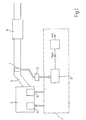
- an UEGO sensor of known type bears the general reference 1 and is able to be placed along an exhaust duct 2 o an internal combustion engine 3 (for example a petrol engine) to obtain information concerning the stoichiometric composition of the composition gases, and finally concerning the A/F (air/fuel) ratio of the mixture fed to the engine.
- an internal combustion engine 3 for example a petrol engine
- the senor 1 is located upstream of a catalytic converter 4 able to reduce polluting substances present in the combustion gases before they are emitted into atmosphere. It remains clear that the sensor 1 could also be located downstream of the catalytic converter 4 to measure the percentage of oxygen present in the exhaust gases emitted into atmosphere after the catalytic process.
- the engine 3 has a petrol supply arrangement 5 to the cylinders (not illustrated), and an ignition arrangement 6 to ignite combustion within the cylinders.
- the engine 3 is controlled by electronic central unit 7 (diagrammatically illustrated), which controls the supply arrangement 5 to regulate in the injection time and consequently, the quantity of fuel to be injected into the cylinders, and controls the ignition arrangement 6 to regulate the ignition moments for combustion within the cylinders.
- the electronic central unit 7 comprises an electric control arrangement 8 for the sensor 1 connected to sensor 1 by means of a connector 9 and able to implement the control method object of this invention.
- the control arrangement 8 is able to process information originating from the sensor 1 to generate an output Vout signal which, according to the present invention, is a digital signal correlated with the quantity of oxygen present in the combustion gases and indicative of the A/F ratio.
- the Vout signal is the digital conversion of a corresponding analog signal proportional to the quantity of oxygen present in the combustion gas.
- the measured A/F ratio is greater than the A/F stoichiometric ratio and the mixture supplied to the engine 3 is said to be lean
- the value of parameter ⁇ m is lower than unity ( ⁇ m ⁇ 1) the measured A/F ratio is lower than the A/F stoichiometric ratio and the mixture supplied to the engine 3 is said to be rich.
- Figure 2 illustrates in greater detail the connection of the UEGO sensor 1 to the control arrangement 8 by means of the connector 9.
- the senor 1 has two electrolytic cells 11 and 12 responding to oxygen ions, respectively termed “Vs sensing cell” and “pumping cell Ip", and a diffusion chamber 13 interposed between the cells 11 and 12 and able to receive the exhaust gas.
- the sensor 1 also has a reference chamber 14, which is located on the opposite side of the diffusion chamber 13 in relation to cell 11, and is in a stoichiometric condition, i.e. presenting an oxygen level equal to that which the exhaust gas would have in the event of the A/F ratio of the mixture fed to the engine being stoichiometric.
- the cell 11 presents at its heads a pair of electrodes 11a and 11b electrically connected to respective connections 9a, 9b of the connector 9.
- the cell 12 has at its heads a pair of electrodes 12a and 12b, of which the electrode 12a is connected electrically to the electrode 11b of cell 11, whereas electrode 12b is connected to a connection 9c of the connector 9.
- the control arrangement 8 has the dual function of electrical supply to the sensor 1 and ensuring a retroactive control action designed to modify the composition of the gases within the diffusion chamber 13.
- the arrangement 8 is able to pilot a pumping current Ip to the electrode 12b of cell 12 to achieve an oxygen ions draining mechanism within the diffusion chamber 13 out to atmosphere (and vice versa) in such a way as to achieve a stoichiometric level within chamber 13.
- the intensity of the control action that is to say the intensity of the pumping current Ip required to maintain a stoichiometric level within the diffusion chamber 13 is the information on the basis whereof the control arrangement 8 generates the output of Vout signal.
- the control arrangement 8 comprises an amplifier 15 which is connected as input to connections 9a and 9b of the connector 9 to receive the Vd signal (voltage), and is able to supply the amplified Vd signal to the subtracter input 17a of a summation node 17.
- the amplified signal Vd assumes values of around 450mV whenever within the diffusion chamber 13 there are gases originating from the combustion of a stoichiometric mixture, and in the meantime assumes values greater than 450 mV (or respectively lower than 450mV) when the gases originate from the combustion of a rich mixture (or respectively a lean mixture).
- the summation node 17 has a summation input 17b to which is supplied a reference signal Vd rif , which represents the reference (or set point) for the amplified Vd signal, and is equal to the amplified value of the signal Vd which is present at the heads of the cell 12 in the event that the exhaust gases emitted from the diffusion chamber 13 originate from the combustion of a stoichiometric mixture.
- Vd rif represents the reference (or set point) for the amplified Vd signal
- the node 17 generates an output error signal Verr, which is defined by the difference between the reference signal Vdrif and the amplified Vd signal, and is represented of the error between the voltage in the heads of cell 11 in the event of stoichiometric conditions and that which effectively is recorded at the heads of cell 12.
- the error signal Verr is supplied to a processing circuit 19 able to process it to provide on output a correction signal Vcorr.
- the processing circuit 19 is defined by a PID controller of known type able to effect a proportional integral derivative transformation (PID) of the Verr signal to generate the Vcorr signal.
- PID proportional integral derivative transformation
- the Vcorr correction signal is supplied to a pilot circuit 22 (of known type), which, on the basis of the Vcorr signal, regulates the intensity of the pumping current Ip supplied to cell 12.
- the Vcorr signal is the input on the basis whereof the pilot circuit 22 corrects the current Ip so that the cell 12 drains the oxygen ions from the diffusion chamber 13 to atmosphere (or vice versa) to originate the stoichiometric conditions in chamber 13.
- the pilot circuit is represented by a voltage/current converter of known type able to convert the Vcorr voltage signal into a corresponding current Ip to be supplied to cell 12.
- the error signal Verr is lower than zero, and the PID controls the pilot circuit 22 so that within cell 12 a current Ip is piloted such as to generate a flow of oxygen ions from atmosphere towards the diffusion chamber 13. In that way by means of the retroactive control, there is a tendency to return chamber 13 to the stoichiometric condition.
- the pilot circuit 22 also, cooperates with an output circuit 23, which in a known manner, converts the pumping current Ip into a Voutm correlated with the composition of the combustion gases present in the exhaust duct 2, or the quantity of oxygen present in the gases output from the engine 3.
- the said exit circuit 23 is thus able to translate the force induced by the control arrangement 8 to maintain a stoichiometric condition in the diffusion chamber 13, into a Vout m signal, which is converted from an analog/digital converter 24 into a Vout m digital signal, which, saving the correction explained below, represents the output signal Vout from the arrangement 8.
- control arrangement 8 has a correction circuit 25 (detailed below) able to ensure correction of the digital- converted Vout m signal so as to ensure that when the engine 3 is running, the Vout signal output from the arrangement 8 itself assumes values effectively representative of the quantity of oxygen present in the exhaust gases.
- the Voutm signal would not effectively express the true percentage of oxygen present in the exhaust gases and therefore would tend to produce an incorrect measurement of the ⁇ m parameter.
- the correction circuit 25 receives on input the Voutm signal output from the converter 25, and its function is to calculate a correction Kcorr parameter able to be applied to the Voutm signal itself to obtain the Vout signal allowing compensation of the said Ip piloting current spreads.
- the sensor 1 needs to be in a controlled atmosphere of which the oxygen percentage is initially known, in such a way that within the diffusion chamber 13, the entry of gases of known stoichiometric composition is possible.
- the percentage of oxygen in gases entering the chamber 13 is known, it is also basically known what nominal value Vnom the required signal Voutm should take in the presence of such a controlled atmosphere.
- the correction circuit 25, as explained further on, is in a position to calculate the correction parameter Kcorr on the basis of the swing of the signal Vout m in relation to the nominal value Vnom.
- the digital-converted Voutm signal is always correct thanks to the Kcorr parameter (according to expression (1)) to originate the Vout signal and make good the said spreads of the piloting current Ip.
- the sensor 1 before its installation in the exhaust duct 2 of the engine 3, the sensor 1 is kept for a given period T in a controlled atmosphere (for example in air) so that the diffusion chamber 13 is surrounded by gases of known oxygen content.
- the correction circuit 25 measures signal Voutm, and knowing nominal value Vnom expected of the said Vout m signal for a given oxygen content, the Kcorr correction parameter value is defined. Having once calculated the Kcorr parameter the sensor is installed along the exhaust duct 2.
- the Kcorr parameter calculation is made with the sensor 1 already installed in a exhaust duct 2, making use of the fact that for a given engine running condition (known as "cut-off") the sensor 1 is surrounded by a flow of pure air.
- the central control 7 calls for the supply arrangement 5 to impose a zero injection time. Consequently, the inside of the cylinders does not receive petrol and the air aspirated by the engine passes directly into the exhaust manifold 2 without undergoing any combustion.
- FIG. 4 illustrates the ⁇ m range discharge procedure as a function of time.
- the Kcorr parameter is calculated when the engine 3 is in the "cut-off" condition for the first time after ignition of the engine 3.
- the course of the digital converted signal Vout m for the time interval T* is determined (see figure 4 ), and may assume differing amplitudes, generally a few seconds for both methodologies.
- the move is made from block 100 to block 110, wherein the mean value Vmean of the signal Vout m in time interval T*, is calculated in a known manner.
- the correction parameter Kcorr is calculated based on the mean value Vmean and the nominal value Vnom (basically known) required of the Vout m signal, on knowing the oxygen percentage of gases coming to sensor 1.
- control arrangement 8 allows avoidance of the need for control arrangement 8 to cooperate with the cited compensation resistance, as occurs in control arrangements of known type, thus allowing a saving from the economic viewpoint.
Landscapes
- Chemical & Material Sciences (AREA)
- Life Sciences & Earth Sciences (AREA)
- Health & Medical Sciences (AREA)
- Biochemistry (AREA)
- General Physics & Mathematics (AREA)
- Electrochemistry (AREA)
- Physics & Mathematics (AREA)
- Analytical Chemistry (AREA)
- Molecular Biology (AREA)
- General Health & Medical Sciences (AREA)
- Chemical Kinetics & Catalysis (AREA)
- Immunology (AREA)
- Pathology (AREA)
- Combined Controls Of Internal Combustion Engines (AREA)
- Electrical Control Of Air Or Fuel Supplied To Internal-Combustion Engine (AREA)
- Measuring Oxygen Concentration In Cells (AREA)
- Crystals, And After-Treatments Of Crystals (AREA)
- Investigating Or Analyzing Materials By The Use Of Magnetic Means (AREA)
Claims (14)
- Steuerungsverfahren für einen linearen Sauerstoffsensor (1) mit den folgenden Phasen:a) Anordnen des Sensors (1) entlang dem Auslasskanal (2) einer Brennkraftmaschine (3) zur Verbreitung eines Teiles des Abgases in einer Diffusionskammer (13) des Sensors (1);b) Empfangen vom Sensor (1) eines ersten Signales (Vd), das die Abweichung zwischen der Zusammensetzung des Gases innerhalb der Diffusionskammer (13) und einer stöchiometrischen Bezugszusammensetzung repräsentiert;c) Steuern (22) eines elektrisches Stromes (Ip) in den Sensor (1) gemäß der Verarbeitung (15, 17, 19) des ersten Signales (Vd) derart, dass ein Sauerstoffionenabzugsmechanismus von und/oder zu der Kammer (13) erzeugt und die Abweichung beseitigt wird;d) Erzeugen (23, 24) auf der Basis des Stromes (Ip) eines Ausgangssignales (Voutm), das, ausgenommen eines Fehlers infolge der Streuungen des Stromes (Ip), proportional zur Menge des in den Abgasen vorhandenen Sauerstoffs ist;
dadurch gekennzeichnet, dass die folgenden Phasen enthalten sind:e) Berechnen (100, 110, 120) eines Korrekturparameters (Kcorr), der zur Verwendung am Ausgangssignal (Voutm) geeignet ist, um die Streuungen des Stromes (Ip) zu beseitigen und das Ausgangssignal (Voutm) proportional zur Menge des in den Abgasen vorhandenen Sauerstoffs zu machen, wobei die Berechnungsphase mit dem in einer gesteuerten Atmosphäre angeordneten Sensor (1) mit Hilfe der Verarbeitung des Ausgangssignales (Voutm) und eines Nennwertes (Vnom), der den theoretischen Wert des Ausgangssignales (Voutm) definiert, in Gegenwart der gesteuerten Atmosphäre durchgeführt wird. - Verfahren nach Anspruch 1, dadurch gekennzeichnet, dass die gesteuerte Atmosphäre durch ein Gas definiert wird, dessen Sauerstoffanteil bekannt ist, und dass der Sensor (1) in der gesteuerten Atmosphäre vor Installation des Sensors (1) im Auslasskanal (2) der Brennkraftmaschine (3) angeordnet wird.
- Verfahren nach Anspruch 1, dadurch gekennzeichnet, dass die gesteuerte Atmosphäre durch reine Luft definiert wird, die von der Brennkraftmaschine (3) entlang dem Auslasskanal (2) emittiert wird, wenn sich die Brennkraftmaschine (3) in einem speziell definierten Betriebszustand (Abschaltung) befindet.
- Verfahren nach Anspruch 3, dadurch gekennzeichnet, dass der Korrekturparameter (Kcorr) berechnet wird, wenn der Sensor (1) von der von der Brennkraftmaschine (3) entlang dem Auslasskanal (2) emittierten Luft umgeben ist, und zwar nach einer Unterbrechung der Kraftstoffzufuhr zu den Zylindern der Brennkraftmaschine (3).
- Verfahren nach einem oder anderen der vorhergehenden Ansprüche, dadurch gekennzeichnet, dass es die Phasen der Speicherung (130) des berechneten Korrekturparameters (Kcorr) umfasst, wobei der gespeicherte Korrekturparameter (Kcorr) mit dem Ausgangssignal (Voutm) verwendet wird, um die momentanen Streuungen (Ip) während des Betriebs der Brennkraftmaschine (3) zu kompensieren.
- Verfahren nach einem oder anderen der vorhergehenden Ansprüche, dadurch gekennzeichnet, dass die Phase an Punkt e) die folgenden Unterphasen umfasst:f) Aufzeichnen (100) des Verhaltens des Ausgangssignales (Voutm) während eines Zeitintervalls (T*), in dem der Sensor (1) von der gesteuerten Atmosphäre umgeben ist;g) Mittelwertbildung (110) des Ausgangssignales (Voutm) während dieses Zeitintervalls (T*), um einen Mittelwert (Vmean) zu erhalten;h) Berechnen des Korrekturparameters (Kcorr) auf der Basis des Mittelwertes (Vmean) und des Nennwertes (Vnom) .
- Verfahren nach Anspruch 6, dadurch gekennzeichnet, dass der Korrekturparameter (Kcorr) nach dem folgenden Ausdruck berechnet wird: die Phase an Punkt e) umfasst die folgenden Unterphasen:

wobei Vnom der Nennwert und Vmean der Mittelwert sind. - Verfahren nach einem oder anderen der vorhergehenden Ansprüche 6-7, dadurch gekennzeichnet, dass dann, wenn der Sensor (1) von Abgasen von der Brennkraftmaschine (3) umgeben ist, von denen Einzelheiten in Bezug auf die stöchiometrische Zusammensetzung benötigt werden, der Korrekturparameter (Kcorr) mit dem Ausgangssignal (Voutm) gemäß der Gleichung

- Verfahren nach Anspruch 2 und einem oder anderen der Ansprüche 5-8, dadurch gekennzeichnet, dass die gesteuerte Atmosphäre von Luft definiert wird, in der der Sensor (1) vor der Installation des Auslasskanals (2) der Brennkraftmaschine (3) gehalten wird, und dass die Berechnung des Korrekturparameters (Kcorr) durchgeführt wird, wenn der Sensor (1) über das vorgegebene Zeitintervall (T*) in Kontakt mit Luft gehalten wird.
- Verfahren nach Anspruch 4 und einem oder anderen der Ansprüche 5-8, dadurch gekennzeichnet, dass das Zeitintervall (T*), in dem das Ausgangssignal (Voutm) aufgezeichnet wird, der Unterbrechung der Kraftstoffzufuhr zu den Zylindern der Brennkraftmaschine (3) folgt und einen Zeitabstand zu dem Moment (T1) besitzt, in dem die Unterbrechung der Kraftstoffzufuhr auftritt.
- Verfahren nach einem der Ansprüche 3, 4 oder 10, dadurch gekennzeichnet, dass der Korrekturparameter (Kcorr) berechnet wird, wenn die Brennkraftmaschine (3) sich zum ersten Male in dem als "Abschaltung" bezeichneten Betriebszustand befindet, wobei eine Unterbrechung der Kraftstoffzufuhr zu den Zylindern der Beendigung der Zündung der Brennkraftmaschine (3) folgt.
- Verfahren nach einem oder anderem der vorhergehenden Ansprüche, dadurch gekennzeichnet, dass der Sensor (1) mindestens eine erste (12) und eine zweite (11) elektrolytische Zelle aufweist, von denen die erste Zelle (12) vom Strom (Ip) gesteuert wird, um die Zusammensetzung der Gase in der Diffusionskammer (13) mit Hilfe des Sauerstoffionenabzugsmechanismus zu steuern, und wobei die zweite Zelle (11) in der Lage ist, das erste Signal (Vd) zuzuführen, während der in die erste Zelle (12) gesteuerte Strom (Ip) durch eine Schaltung (15, 17, 19, 22) mit Retrowirkung reguliert wird, die das erste eingegebene Signal (Vd) empfängt und in der Lage ist, die Verarbeitung gemäß Punkt c) sicherzustellen.
- Verfahren nach Anspruch 12, dadurch gekennzeichnet, dass die Steuerungsphase gemäß Punkt c) die folgenden Unterphasen umfasst:i) eine Verstärkung (15) des ersten Signales (Vd);m) eine Erzeugung eines Bezugssignales (Vdrif), das den Wert des ersten Signales (Vd) definiert, der im Falle des Vorhandenseins einer stöchiometrischen Bezugszusammensetzung in der Diffusionskammer (13) verstärkt ist;n) einen Vergleich (17) des Bezugssignales (Vdrif) mit dem verstärkten ersten Signal (Vd), um ein Fehlersignal (Verr) zu erzeugen;o) das Verarbeiten eines Fehlersignales (Verr) mit Hilfe einer Steuereinheit (19);p) das Regulieren (22) der Intensität des gesteuerten Stromes (Ip) in der ersten Zelle (12) in Abhängigkeit vom Ergebnis der Verarbeitung durch die Steuereinheit (19) derart, dass der Sauerstoffionenabzugsmechanismus von der und/oder zu der Diffusionskammer (13) das Löschen des Fehlersignales (Verr) umfasst, um die stöchiometrische Bezugszusammensetzung in der Kammer (13) zu erzeugen.
- Verfahren nach Anspruch 13, dadurch gekennzeichnet, dass die Steuereinheit (19) eine Proportional-Integral-Ableitungsverarbeitungsoperation des Fehlersignales (Verr) durchführt.
Applications Claiming Priority (2)
| Application Number | Priority Date | Filing Date | Title |
|---|---|---|---|
| IT1998BO000435A IT1306316B1 (it) | 1998-07-16 | 1998-07-16 | Metodo di controllo di una sonda lineare di ossigeno. |
| ITBO980435 | 1998-07-16 |
Publications (2)
| Publication Number | Publication Date |
|---|---|
| EP0973030A1 EP0973030A1 (de) | 2000-01-19 |
| EP0973030B1 true EP0973030B1 (de) | 2008-06-25 |
Family
ID=11343307
Family Applications (1)
| Application Number | Title | Priority Date | Filing Date |
|---|---|---|---|
| EP99113851A Expired - Lifetime EP0973030B1 (de) | 1998-07-16 | 1999-07-15 | Methode zur Steuerung eines linearen Sauerstoffsensors |
Country Status (7)
| Country | Link |
|---|---|
| US (1) | US6223735B1 (de) |
| EP (1) | EP0973030B1 (de) |
| JP (1) | JP2000081416A (de) |
| BR (1) | BR9904565A (de) |
| DE (1) | DE69938949D1 (de) |
| ES (1) | ES2310023T3 (de) |
| IT (1) | IT1306316B1 (de) |
Cited By (1)
| Publication number | Priority date | Publication date | Assignee | Title |
|---|---|---|---|---|
| CN108398527A (zh) * | 2018-01-31 | 2018-08-14 | 广西玉柴机器股份有限公司 | 一种天然气发动机氧传感器检测方法 |
Families Citing this family (7)
| Publication number | Priority date | Publication date | Assignee | Title |
|---|---|---|---|---|
| US7055372B2 (en) * | 2002-11-01 | 2006-06-06 | Visteon Global Technologies, Inc. | Method of detecting cylinder ID using in-cylinder ionization for spark detection following partial coil charging |
| US7251571B2 (en) * | 2003-09-05 | 2007-07-31 | Visteon Global Technologies, Inc. | Methods of diagnosing open-secondary winding of an ignition coil using the ionization current signal |
| JP2012504236A (ja) * | 2008-09-30 | 2012-02-16 | イルジン カッパー ホイル カンパニー リミテッド | 窒素酸化物ガスセンサー |
| US9309838B2 (en) | 2013-08-20 | 2016-04-12 | Ford Global Technologies, Llc | Methods and systems for indicating water at an oxygen sensor based on sensor heater power consumption |
| US9273621B2 (en) * | 2013-10-11 | 2016-03-01 | Ford Global Technologies, Llc | Methods and systems for an oxygen sensor |
| US9328679B2 (en) | 2013-10-11 | 2016-05-03 | Ford Global Technologies, Llc | Methods and systems for an oxygen sensor |
| US9181887B2 (en) * | 2013-10-11 | 2015-11-10 | Ford Global Technologies, Llc | Methods and systems for an oxygen sensor |
Family Cites Families (10)
| Publication number | Priority date | Publication date | Assignee | Title |
|---|---|---|---|---|
| JPS58161859A (ja) * | 1982-03-19 | 1983-09-26 | Hitachi Ltd | 酸素濃度検出器 |
| JPS58162858A (ja) * | 1982-03-23 | 1983-09-27 | Hitachi Ltd | 酸素濃度検出器 |
| US4939658A (en) * | 1984-09-03 | 1990-07-03 | Hitachi, Ltd. | Control method for a fuel injection engine |
| JPH0727391Y2 (ja) * | 1986-02-04 | 1995-06-21 | 本田技研工業株式会社 | 内燃エンジンの空燃比制御装置 |
| JP2553509B2 (ja) * | 1986-02-26 | 1996-11-13 | 本田技研工業株式会社 | 内燃エンジンの空燃比制御装置 |
| JPH0737776B2 (ja) * | 1986-03-04 | 1995-04-26 | 本田技研工業株式会社 | 内燃エンジンの空燃比制御方法 |
| JP3138498B2 (ja) * | 1991-06-14 | 2001-02-26 | 本田技研工業株式会社 | 内燃機関の空燃比制御装置 |
| JP2942445B2 (ja) * | 1993-08-20 | 1999-08-30 | 株式会社日立製作所 | 空燃比センサ |
| DE4344961B4 (de) * | 1993-12-30 | 2004-05-06 | Robert Bosch Gmbh | Auswertevorrichtung für das Signal einer Sauerstoffsonde |
| US5558752A (en) * | 1995-04-28 | 1996-09-24 | General Motors Corporation | Exhaust gas sensor diagnostic |
-
1998
- 1998-07-16 IT IT1998BO000435A patent/IT1306316B1/it active
-
1999
- 1999-07-15 ES ES99113851T patent/ES2310023T3/es not_active Expired - Lifetime
- 1999-07-15 EP EP99113851A patent/EP0973030B1/de not_active Expired - Lifetime
- 1999-07-15 DE DE69938949T patent/DE69938949D1/de not_active Expired - Fee Related
- 1999-07-16 JP JP11203359A patent/JP2000081416A/ja active Pending
- 1999-07-16 US US09/354,440 patent/US6223735B1/en not_active Expired - Fee Related
- 1999-07-16 BR BR9904565-6A patent/BR9904565A/pt not_active Application Discontinuation
Cited By (2)
| Publication number | Priority date | Publication date | Assignee | Title |
|---|---|---|---|---|
| CN108398527A (zh) * | 2018-01-31 | 2018-08-14 | 广西玉柴机器股份有限公司 | 一种天然气发动机氧传感器检测方法 |
| CN108398527B (zh) * | 2018-01-31 | 2021-02-23 | 广西玉柴机器股份有限公司 | 一种天然气发动机氧传感器检测方法 |
Also Published As
| Publication number | Publication date |
|---|---|
| IT1306316B1 (it) | 2001-06-04 |
| BR9904565A (pt) | 2000-10-03 |
| DE69938949D1 (de) | 2008-08-07 |
| ES2310023T3 (es) | 2008-12-16 |
| ITBO980435A1 (it) | 2000-01-16 |
| US6223735B1 (en) | 2001-05-01 |
| EP0973030A1 (de) | 2000-01-19 |
| JP2000081416A (ja) | 2000-03-21 |
Similar Documents
| Publication | Publication Date | Title |
|---|---|---|
| US6720534B2 (en) | Power supply control system for heater used in gas sensor | |
| US6294075B1 (en) | Method of controlling and diagnosing the heater of an engine exhaust gas composition sensor | |
| US6870142B2 (en) | Power supply control system for heater used in gas sensor | |
| JP5950917B2 (ja) | センサ素子の温度調整を行うための方法 | |
| US10551364B2 (en) | Control system and control method for internal combustion engine | |
| US10865725B2 (en) | Exhaust system for internal combustion engine | |
| US8798938B2 (en) | Method for determining a gas concentration in a measuring gas by means of a gas sensor | |
| EP0994345B1 (de) | Leistungsversorgungssteuersystem für die Heizung eines Gaskonzentrationsfühlers | |
| US9068937B2 (en) | Method and device for examining an exhaust gas sensor | |
| US20160223488A1 (en) | Gas sensor control device | |
| WO2015124992A1 (en) | Control system and control method for internal combustion engine | |
| US20090120161A1 (en) | Gas sensor control device | |
| EP1612549A2 (de) | Gaskonzentrationsmessvorrichtung mit kompensiertem Ausgangsfehler | |
| US12203399B2 (en) | Method for determining a state parameter of an exhaust gas sensor | |
| EP0973030A1 (de) | Methode zur Steuerung eines linearen Sauerstoffsensors | |
| US5758310A (en) | Apparatus for determining the condition of an air-fuel ratio sensor | |
| US7776194B2 (en) | Gas concentration measuring apparatus designed to compensate for output error | |
| US10627365B2 (en) | Sensor control apparatus and sensor control system | |
| EP0973029B1 (de) | Lineares Sauerstoffsensorsystem | |
| US10400699B2 (en) | Abnormality determination device | |
| JP7274814B2 (ja) | 電子制御装置 | |
| US7584642B2 (en) | Procedure to calibrate a signal supplied by a lambda sensor and device to implement the procedure | |
| JP2005504292A (ja) | 窒素酸化物センサの作動方法および回路 | |
| JP2942445B2 (ja) | 空燃比センサ | |
| JP2010014562A (ja) | 空燃比検出装置 |
Legal Events
| Date | Code | Title | Description |
|---|---|---|---|
| PUAI | Public reference made under article 153(3) epc to a published international application that has entered the european phase |
Free format text: ORIGINAL CODE: 0009012 |
|
| AK | Designated contracting states |
Kind code of ref document: A1 Designated state(s): DE ES FR GB SE |
|
| AX | Request for extension of the european patent |
Free format text: AL;LT;LV;MK;RO;SI |
|
| 17P | Request for examination filed |
Effective date: 20000110 |
|
| RIN1 | Information on inventor provided before grant (corrected) |
Inventor name: CECCARINI, DANIELE Inventor name: SECCO, MARCO Inventor name: POGGIO LUCA |
|
| AKX | Designation fees paid |
Free format text: DE ES FR GB SE |
|
| GRAP | Despatch of communication of intention to grant a patent |
Free format text: ORIGINAL CODE: EPIDOSNIGR1 |
|
| RAP1 | Party data changed (applicant data changed or rights of an application transferred) |
Owner name: MAGNETI MARELLI POWERTRAIN S.P.A. |
|
| GRAS | Grant fee paid |
Free format text: ORIGINAL CODE: EPIDOSNIGR3 |
|
| GRAA | (expected) grant |
Free format text: ORIGINAL CODE: 0009210 |
|
| RAP1 | Party data changed (applicant data changed or rights of an application transferred) |
Owner name: MAGNETI MARELLI POWERTRAIN S.P.A. |
|
| AK | Designated contracting states |
Kind code of ref document: B1 Designated state(s): DE ES FR GB SE |
|
| REG | Reference to a national code |
Ref country code: GB Ref legal event code: FG4D |
|
| REF | Corresponds to: |
Ref document number: 69938949 Country of ref document: DE Date of ref document: 20080807 Kind code of ref document: P |
|
| REG | Reference to a national code |
Ref country code: SE Ref legal event code: TRGR |
|
| PGFP | Annual fee paid to national office [announced via postgrant information from national office to epo] |
Ref country code: ES Payment date: 20080818 Year of fee payment: 10 |
|
| PGFP | Annual fee paid to national office [announced via postgrant information from national office to epo] |
Ref country code: FR Payment date: 20080814 Year of fee payment: 10 |
|
| REG | Reference to a national code |
Ref country code: ES Ref legal event code: FG2A Ref document number: 2310023 Country of ref document: ES Kind code of ref document: T3 |
|
| PGFP | Annual fee paid to national office [announced via postgrant information from national office to epo] |
Ref country code: GB Payment date: 20080929 Year of fee payment: 10 |
|
| PGFP | Annual fee paid to national office [announced via postgrant information from national office to epo] |
Ref country code: DE Payment date: 20080922 Year of fee payment: 10 |
|
| PGFP | Annual fee paid to national office [announced via postgrant information from national office to epo] |
Ref country code: SE Payment date: 20080825 Year of fee payment: 10 |
|
| PLBE | No opposition filed within time limit |
Free format text: ORIGINAL CODE: 0009261 |
|
| STAA | Information on the status of an ep patent application or granted ep patent |
Free format text: STATUS: NO OPPOSITION FILED WITHIN TIME LIMIT |
|
| 26N | No opposition filed |
Effective date: 20090326 |
|
| EUG | Se: european patent has lapsed | ||
| GBPC | Gb: european patent ceased through non-payment of renewal fee |
Effective date: 20090715 |
|
| REG | Reference to a national code |
Ref country code: FR Ref legal event code: ST Effective date: 20100331 |
|
| PG25 | Lapsed in a contracting state [announced via postgrant information from national office to epo] |
Ref country code: FR Free format text: LAPSE BECAUSE OF NON-PAYMENT OF DUE FEES Effective date: 20090731 |
|
| PG25 | Lapsed in a contracting state [announced via postgrant information from national office to epo] |
Ref country code: GB Free format text: LAPSE BECAUSE OF NON-PAYMENT OF DUE FEES Effective date: 20090715 |
|
| PG25 | Lapsed in a contracting state [announced via postgrant information from national office to epo] |
Ref country code: DE Free format text: LAPSE BECAUSE OF NON-PAYMENT OF DUE FEES Effective date: 20100202 |
|
| REG | Reference to a national code |
Ref country code: ES Ref legal event code: FD2A Effective date: 20090716 |
|
| PG25 | Lapsed in a contracting state [announced via postgrant information from national office to epo] |
Ref country code: ES Free format text: LAPSE BECAUSE OF NON-PAYMENT OF DUE FEES Effective date: 20090716 |
|
| PG25 | Lapsed in a contracting state [announced via postgrant information from national office to epo] |
Ref country code: SE Free format text: LAPSE BECAUSE OF NON-PAYMENT OF DUE FEES Effective date: 20090716 |