EP0970596B1 - Schneidkopf mit Fadenaufladung ohne Entfernung der Spule - Google Patents
Schneidkopf mit Fadenaufladung ohne Entfernung der Spule Download PDFInfo
- Publication number
- EP0970596B1 EP0970596B1 EP99830425A EP99830425A EP0970596B1 EP 0970596 B1 EP0970596 B1 EP 0970596B1 EP 99830425 A EP99830425 A EP 99830425A EP 99830425 A EP99830425 A EP 99830425A EP 0970596 B1 EP0970596 B1 EP 0970596B1
- Authority
- EP
- European Patent Office
- Prior art keywords
- spool
- grass
- cutting head
- teeth
- housing
- Prior art date
- Legal status (The legal status is an assumption and is not a legal conclusion. Google has not performed a legal analysis and makes no representation as to the accuracy of the status listed.)
- Expired - Lifetime
Links
Images


Classifications
-
- A—HUMAN NECESSITIES
- A01—AGRICULTURE; FORESTRY; ANIMAL HUSBANDRY; HUNTING; TRAPPING; FISHING
- A01D—HARVESTING; MOWING
- A01D34/00—Mowers; Mowing apparatus of harvesters
- A01D34/01—Mowers; Mowing apparatus of harvesters characterised by features relating to the type of cutting apparatus
- A01D34/412—Mowers; Mowing apparatus of harvesters characterised by features relating to the type of cutting apparatus having rotating cutters
- A01D34/416—Flexible line cutters
- A01D34/4161—Means for feeding cutter line
- A01D34/4163—Means for feeding cutter line by triggered line feedout, e.g. bump-feeding
Definitions
- the present invention relates to a grass-cutting head for brushcutters or similar appliances.
- the invention relates to a grass-cutting head of the type that comprises a housing, at least one spool placed in the housing and on which one or more cutting lines can be wound, and a mechanism for feeding the cutting line from the spool to restore the length of the cutting line projecting from the housing following wear due to the use of the head, and in which the feed mechanism includes a spring-action member.
- Heads of the kind indicated above are widely used in this sphere. Examples of this kind of head are disclosed in US-A-5,095,688, US-A-4,823,465, US-A-4,893,410, US-A-4,882,843, US-A-4,274,201, US-A-4,584,771 and US-A-4,524,515.
- All these heads possess systems for lengthening the line (i.e. a feed mechanism) with spring-action members which act on a moveable slider or directly on the spool.
- EP-A-784919 discloses a cutting head according to the preamble of claim 1.
- This known cutting head has been designed in order to allow refilling of the spool with new cutting line without disassembling the head. In order to wind new line on the spool, a portion of said line has to be passed diametrically through the head.
- the head includes a housing with a body portion and a cover. The cover is not removed when new cutting line is wound on the spool. Said cover keeps the spool and a spring action member acting on the spool within the housing of the cutting head.
- the head is so configured that the spool is accessible from the outside to enable a supply of cutting line to be wound onto it without taking the spool out of the housing, means being provided to hold the spool in the head when the latter is opened to make the spool accessible for reloading of the line.
- the cutting line is advantageously passed through the feed bushings, in the opposite direction to the normal direction of feed during use.
- the grass-cutting head possesses a cutting line feed mechanism of the type comprising a spring-action member.
- retention members prevent the spring-action member and/or the spool which the latter acts upon and/or other parts of the feed mechanism from escaping from the housing in the head when the head is opened to insert the ends of the supply of line into the spool.
- the retention members comprise anti-rotation means that allow manual rotation of the spool in the line winding direction so that the supply of cutting line is wound onto it, and that prevent or otherwise obstruct spontaneous rotation of the spool in the line unwinding direction.
- anti-rotation means facilitate the winding of the supply of line onto the spool.
- the grass-cutting head comprises a feed mechanism that has stop teeth integral with the spool and arresting stops engaging with said teeth to define angularly offset positions of said spool.
- An actuating slider is provided to cause an angular step by step rotation of the spool inside the housing in the cutting line unwinding direction when the head is spinning. The action of the actuating slider is opposed by the spring-action member, which forms a slider return means.
- the feed mechanism may also be of the automatic type.
- the slider can act on an axially moveable spool that carries two series of stop teeth which engage with corresponding stops or groups of stops integral with the housing.
- the stop teeth may again be integral with the spool, which however is situated in a fixed axial position, while the stop teeth engage with a moveable slider comprising the stops that engage with the teeth on the spool.
- the housing may comprise a first portion through which there extends an axial hub that transmits the rotary drive to the grass-cutting head.
- the spool Inside this housing portion is the spool from which the line is fed through bushings in the circumferential wall of the housing portion.
- a support is also provided for the spool mounted on the axial hub and elastically pressed against the first housing portion. The support retains the spool inside the housing.
- Said support possesses axially elongate openings through which pass the moveable stops carried by the actuating slider. The moveable stops engage with the teeth on the spool.
- An annular cover is also provided in order to close the housing around the spool support.
- the spool support may comprise, in an especially advantageous embodiment, end teeth engaging with the corresponding end teeth on the housing portion, thus forming anti-rotation means which prevent or obstruct spontaneous rotation of the spool in the unwinding direction.
- the teeth may be shaped so as to allow rotation of the spool support in the winding direction and prevent rotation in the opposite direction.
- inserts made of friction material may be used to increase the coefficient of friction.
- the spool is axially moveable under the action of an actuating slider, against which the spring-action member of the line feed mechanism acts.
- the spring-action member which also acts on the spool, the latter is held against the retention members which in this case are integral with the housing.
- the anti-rotation means that prevent or otherwise obstruct rotation of the spool in the cutting line unwinding direction may be arranged between the spool and the retention members.
- These anti-rotation means may comprise a layer of friction material or teeth of various shapes.
- the retention members may take various forms, some of which will be described in greater detail with reference to the examples of embodiments illustrated in the appended drawings.
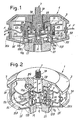
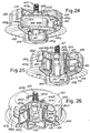
- FIG. 1 A first embodiment of the head according to the invention is illustrated in Figs. 1 and 2.
- the head has the general reference 1 and comprises a housing consisting of a first portion 3 containing a spool 5 on which is wound a cutting line F, depicted as a series of turns in the longitudinal section of Fig. 1.
- the portion 3 of the housing has a cylindrical circumferential wall 3A with bushings 4 through which the cutting line F passes out.
- Extending axially through the inside of the housing portion 3 is a hub 7 with a threaded portion 7A and a hexagonal-section portion 7B coupled in torsion inside the through seat formed in the portion 3 of the housing.
- the hub 7 is locked to the portion 3 of the housing by a journal 9 that screws onto a second threaded portion 7C of the hub 7 and that has an elastic ring 11.
- a component 13 that forms a support for the spool 5, being provided with a collar 13A on which the spool 5 sits.
- the support 13 is held against the portion 3 of the housing by a spring-action member consisting of a helical spring 17 housed in a cylindrical seat formed in the support 13. Inside this cylindrical seat is a moveable actuating slider 19 with projections 19A that project through longitudinal slots 13X in the cylindrical wall of the support 13.
- the projections 19A form stops acting on two series of teeth 5A and 5B which are offset relative to each other angularly and axially inside the through hole of the spool 5.
- the actuating slider 19 is pushed by the spring-action member 17 against a knob 21 mounted on and retained by the journal 9.
- a basically cylindrical closing wall 13B on which is mounted an annular cover 25.
- This cover has an edge 25A that surrounds the free edge of the circumferential wall 3A of the housing portion 3.
- the cover 25 may be held in position by its interference with the closing wall 13B and/or by interference between the edge 25A and the circumferential wall 3A, or by means of spring-action projections.
- the anchor holes 5D are in line with slots 5C in the lower flange 5G of the spool 5.
- the initial end of the new supply of line can be passed through the bushings 4 and through the radial slots 5C to allow the operator to grasp it in the area made accessible by the removal of the annular cover 25, and then insert it in the corresponding anchor hole 5D.
- the operator by twisting the closing wall 13D of the spool support 13, can rotate, in the winding direction, the assembly made up of the button 21, the actuating slider 19, the support 13 and the spool 5 around the hub 7 axis. Rotation in the winding direction is permitted by the shaping of sawtooth-section end teeth 29 formed on that portion of the support 13 which is pushed against the housing portion 3, the latter having complementary teeth, as can be seen in particular in the cutaway view, Fig. 2.
- the system of mutual locking between the housing portion 3, the support 13 and the knob 21 may differ from this.
- the central hub 7 may be omitted and the connection may be provided by a system of spring-action fingers.
- the connection between the head and the brushcutter may be provided by a snap-engaging quick-coupling system or the like, of a type known per se, rather than by means of a threaded journal.
- the knob 21 and the actuating slider 19 may be constructed in one piece.
- the journal 9 may be screwed in by a socket wrench passing through a hole in the knob 21, or the latter may be coupled in torsion to the journal 9 to enable it to rotate.
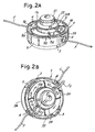
- Figs. 2A and 2B show a perspective view of a head equivalent to the head shown in Figs. 1 and 2 in the open condition and show the operation of inserting a new supply of cutting line F. Parts identical or equivalent to those of Figs. 1 and 2 are indicated by the same reference numbers.
- the annular cover 25 has been removed to allow access from the outside to the underside of the spool 5.
- This spool has slots 5C which are closed off toward the edge of the respective flange of the spool, rather than open as in Fig. 1.
- the lower flange 5G of the spool 5 is provided on its outermost surface with arcuate projections 5H to facilitate the winding of the new supply of cutting line F by hand.
- the knob 21 is made of a smaller diameter than the knob 21 of Figs. 1 and 2, and a protective membrane 22 is arranged between it and the annular closing wall 138 of the support 13.
- Figs. 2A and 2B Also shown in Figs. 2A and 2B are spring-action tabs 6 formed integrally with the housing portion 3. These are for fastening the annular cover 25 (omitted in Figs. 2A and 2B) in place.
- Fig. 2A shows the ends Fx of two lengths of cutting line F that have been passed from the outside of the housing 3 in through the bushings 4.
- the ends Fx project out through the slots 5C and can therefore be grasped by the user, pulled further to draw more line F through the bushings 4 and then inserted - thereby forming a loop Fy (Fig. 2B) - in the anchor holes 5D.
- the line F can then be pulled radially from the outside to take up the loop Fy and then be wound up by turning the spool 5 with the aid of the arcuate projections 5H.
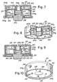
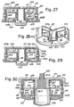
- Figs. 3 and 4 show a different embodiment of the head according to the invention.
- the head indicated by the general reference 101, comprises a housing made up of a main portion 103 and a lower cover 106. Inside the housing is a spool 105 with two annular flanges 105X and 105Y.
- the spool 105 includes a central through hole through which extends a cylindrical skirt 103A integral with the portion 103 of the housing.
- a spring-action component 117 in the form of a helical spring extends between the cylindrical skirt 103A and the inner wall of the axial through hole of the spool 105. The spring-action member pushes the spool against a lower slider 119 projecting from the housing cover 106.
- teeth 126 On the outside of the upper flange 105X of the spool 105 are a plurality of teeth 124 while on the outside of the lower flange 105Y are teeth 126 offset angularly relative to the teeth 124.
- the shape and the position of the teeth 126 can be seen particularly in Fig. 4 where for greater clarity the cover 106 and its projecting knob 119 have been removed.
- the upper teeth 124 engage with stops defined by fingers 128 formed on the upper wall of the portion 103 of the housing containing the spool 105, while the lower teeth 126 engage with stops formed by similar fingers on the cover 106, though these latter fingers are not visible as they are offset at an angle of 90° to the fingers 128.
- the circumferential wall 103B contains bushings 104 for the passage of the cutting line wound onto the spool 105, this line being omitted from the figure for greater clarity.
- the spool 105 is held in place axially by tabs 141 fitted into corresponding slots in the circumferential wall 103B of the housing portion 103.
- the tabs 141 form a stop for the lower surface of the flange 105X of the spool 105, preventing the latter escaping when the cover 106 is removed.
- Removing the cover 106 and actuating slider 119 gives free access to the underside of the spool 105 to allow a new supply of line to be anchored in anchor holes similar to those marked 5D in Figs. 1 and 2 and not shown, for simplicity of the drawing in Figs. 3 and 4.
- the spool 105 and the spring-action member 117 remain in their positions inside the housing portion 103.
- the line is wound in by, for example, pushing the teeth 126 and turning the spool in the winding direction, conveniently indicated by an arrow on the lower face of the flange 105Y of the spool.
- the spool is provided with teeth 143 on the lower surface of the upper flange 105X. The teeth 143 engage with corresponding teeth 145 on the tabs 141.
- Figs. 5 and 6 show an embodiment equivalent to that of Figs. 3 and 4 and identical parts are indicated by the same reference numbers.
- the tabs 141 engage with teeth 143 on the lower face of the lower flange 105Y of the spool 105.
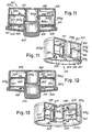
- Figs. 7 and 8 show a variant of the head seen in Figs. 3 and 4. Identical or corresponding parts are indicated by the same reference number increased by 100. So, for example, the head as a whole has the reference 201 and the housing portion 203. In this version the spool 205 is held in position, to prevent it from escaping when the cover 206 is opened, by spring-action tabs 241 formed integrally with the wall 203B of the housing portion 203. To simplify the drawing, Fig. 8 omits not only the cover 206 and the actuating slider 219 but also the spring-action member 217.
- Figs. 9 and 10 Shown in Figs. 9 and 10 is a variant of the head seen in Figs. 7 and 8, in which the spring-action tabs 241, again formed integrally with the wall 203B of the housing portion 203, engage with the lower flange 205Y of the spool 205, rather than with its upper flange. Parts identical or corresponding to those of Figs. 7 and 8 are indicated by the same reference numbers.
- the slider 119 or 219 may be formed in one piece with its respective spool 105, 205.
- Figs. 11 and 12 show a variant of the head depicted in Figs. 9 and 10. Identical or corresponding parts are indicated by the same reference numbers increased by 100 over the numbers given in the embodiment in Figs. 9 and 10.
- the lower flange 305Y of the spool 305 possesses teeth 343 that engage with pegs 341 inserted through the wall 303D of the housing portion 303.
- the pegs 341 have the same function as the tabs 241 and 141 of the earlier embodiments.
- the line feed mechanism is the same as that described above.
- the dimensions of the pegs 341 are such as to ensure, in conjunction with the teeth 343, the anti-rotation action of the spool 305 in order to prevent spontaneous unwinding.
- the pegs 341 or the tabs 141, 241 may also be replaced by other annular retention members built into the internal cylindrical wall of the housing portion of the head.
- Figs. 13 and 14 show a variant of the head seen in Figs. 11 and 12, such that the pegs 341 engage with the upper flange 305X of the spool 305, on the underside of which latter are the teeth 343.
- Identical numbers indicate parts identical or corresponding to those of Figs. 11 and 12.
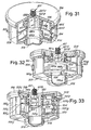
- Figs. 15-18 show, in various cross sections and perspective views, another embodiment of the head according to the invention.
- the head designated 401 as a whole, comprises a housing with a main portion 403 that has bushings 404 on its circumferential wall 403B for the cutting line to be passed from the inside to the outside of the housing.
- the line is wound onto a spool 405 having flanges 405X and 405Y and holes 405D in which the ends of the cutting line are anchored.
- 407 denotes a hub comprising a threaded projecting end 407A for connection to the brushcutter.
- 407B denotes a portion of the hub 407 of hexagonal section for transmitting the rotary drive to the head. For this purpose the portion 407B sits in a seat formed in the portion 403 of the housing.
- the head is closed on the underside by a cover 406 which is fixed to the portion 403 of the housing by spring-action tabs 406A engaging in windows 403C in the circumferential wall 403B of the housing portion 403.
- the cover 406 is released by pressing inward from the outside on the spring-action tabs 406A to disengage them from the windows 403C.
- the spool 405 is provided with a series of upper teeth 424 and a series of lower teeth 426 which engage with respective stops 428 and 430 on the portion 403 and on the cover 406, respectively.
- the teeth 424 and 426 and the stops 428 and 430 are angularly offset to allow the cutting line to be fed out gradually step by step from the spool 405 through the bushings 404 to compensate for line wear.
- the spool 405 is moved axially so that there is alternate engagement between the teeth 426 and the stops 430 on the one hand, and between the teeth 424 and the stops 428 on the other.
- the axial movement of the spool 405 is brought about by pressure on the actuating slider 419 which pushes the spool 405 up, overcoming the elastic force of the spring-action member 417 which is situated between a collar 403X (integral with the portion 403 of the housing) and an annular shoulder 405S on the spool 405.
- an axial retention member 451 comprising a lower plate 451A and spring-action tabs 451E that engage in windows 403Y formed in the collar 403X integral with the housing portion 403.
- the discoidal portion 451A of the retention member 451 has teeth 451B engaging with corresponding teeth 405F on the spool 405.
- the teeth 451B and 405F form anti-rotation means to prevent spontaneous rotation of the spool 405 in the unwinding direction while a new supply of line is being wound on.
- This operation takes place as follows.
- the actuating slider 419 is removed together with the cover 406, exposing the lower surface of the spool 405, which is held in place, along with the spring-action member 417, by the retention members 451.
- the new supply of line is passed in from the outside through the bushings 404 and the operator can easily engage the initial end of a length of line in the corresponding hole 405D formed on the spool.
- the user winds a supply of line onto the spool 405 by rotating it in the winding direction.
- the torque applied by the operator on the spool generates an axial force through the teeth 405F, 451B, which overcomes the force of the spring-action member 417, allowing the teeth 405F to ride over the teeth 451B so that the spool 405 rotates in the winding direction.
- the force of the spring 417 and the shape of the teeth 451B, 405F are sufficient to prevent spontaneous rotation in the opposite direction.
- the housing can be reclosed by once again fitting on the cover 406 with a snap-action, having first inserted the actuating slider 419 into its central seat in the cover 406.
- Figs. 19-22 show a modified embodiment of the head seen in Figs. 15-18. Identical numbers indicate parts identical or corresponding to those of the embodiment seen in Figs. 15-18.
- FIG. 19-22 differs in the different method of anchorage of the retention members 451, which in this case are fixed to the axial hub 407 which extends down into the lower region of the head, where a screw 408 fastens the retention members 451 consisting of a disk 451A with the teeth 451B.
- Figs. 23-26 show a modified embodiment of the head seen in Figs. 15-18. This embodiment differs from the previous embodiment by having a different design of the retention members 451 of the spool 405. Identical or corresponding parts are indicated by the same reference numbers as were used in Figs. 15-18.
- the retention members 451 are held in place by spring-action fingers again marked 451E in end windows marked 403Z in the top surface of the housing portion 403.
- the seat for the hub 407 is formed in a sleeve 451C in the retention members 451, rather than directly on the housing portion 403 as in Figs. 15-18.
- the latter portion again has a collar 403X coaxial with the sleeve 451C of the retention members 451, forming a stop for the spring-action member 417 which is housed between this stop and an annular stop formed in the internal through hole of the spool 405.
- the retention members 451 again comprise a discoidal terminal portion 451A that forms end teeth 451B engaging with the teeth 405F of the spool.
- the retention members 451 may also be formed in one piece with the housing portion 403 and may have spring-action tabs at the lower end for engagement on the spool. This solution is illustrated diagrammatically in Figs. 27 and 28, where identical numbers denote parts identical or corresponding to those of Figs. 23-26.
- the retention members 451 again retain the spool 405 in its position against the action of the spring-action member 417. They consist in the present case of spring-action tabs extending axially through the inside of the housing portion 403, and have end teeth engaging with the teeth 405F of the spool.
- the spool can be removed from the housing by radially compressing the spring-action tabs forming the retention members 451, whereas in the previous version release was by acting on the tabs 451E.
- Fig. 29 shows an embodiment with some slight modifications compared with that of Figs. 27 and 28.
- the mutually meshing end teeth on the retention members 451 and on the spool 405F are replaced by a ring 460 of friction material interposed between the tabs forming the retention members 451 and the lower surface of the spool 405.
- This solution which involves using a friction material rather than a toothed coupling to prevent or hinder spontaneous rotation in the unwinding direction, can also be adopted in the embodiments described earlier.
- Figs.30-33 show yet another embodiment of the head according to the invention.
- the head which bears the general reference 501, comprises a housing formed largely by a main portion 503 with a circumferential wall 503B containing outlet bushings 504 for the cutting line which is wound onto a spool 505 housed inside the housing.
- the spool has flanges 505X and 505Y with teeth 524 and 526 projecting outward from the flanges 505X, 505Y so as to engage with respective stops 528 and 530.
- the stops 530 are formed on the bottom of the housing portion 503, while the stops 528 are formed on the inner wall of a cover 506 which fits above the housing portion 503 to close the housing.
- the cover 506 is held in place by spring-action tabs 503C extending axially along the circumferential wall 503B of the housing portion 503.
- spool 503B Around the circumferential wall 503B are windows 503D into which spring-action tabs 561E belonging to retention members with the general reference 561 engage. These retention members define an annular seat 561S that runs around an axial sleeve 506M formed in one piece with the cover 506.
- a spring-action member 517 formed by a helical spring which is contained between the seat 561S and the upper surface of the upper flange 505X of the spool 505. The spring-action member 517 thus pushes the spool 505 against an actuating slider 519 projecting down from the housing portion 503.
- the cover 506 is traversed by a hub 507 with the threaded portion 507A and a hexagonal-section portion 507B which is coupled in torsion in a seat of similar cross section formed in the sleeve 506M of the cover 506.
- the threaded portion 507A of the hub 507 fits onto the brushcutter, and the hub itself transmits the rotation to the head 501.
- the cutting line is fed by pressing the actuating slider 519 in so that it overcomes the force of the spring-action member 517 and displaces the spool 505 axially to bring the teeth 524 and 526 into engagement alternately with the stops 528 and 530, respectively.
- the angular offset between the teeth 524, 526 and the stops 528, 530 allows the spool 505 to rotate in steps under the impulse of centrifugal force when the head 501 is spinning, thus giving a gradual lengthening of the cutting line.
- a new supply of cutting line can be inserted into the spool 505 without removing the spring-action member 517 and said spool, simply by removing the cover 506 by applying pressure to the two spring-action tabs 503C.
- This allows access from the outside to the upper part of the spool 505 so that the user can insert the initial end of a new supply of line from the outside through the bushings 504 and anchor this end of the line to the spool, for example by pushing it into the holes 505D as shown in Fig. 30.
- Winding is by rotating the spool in the winding direction.
- Rotation is permitted because the lower teeth 526 are sloping on one side as shown at 526X in Fig. 32. This allows the teeth 526 to ride over the stops 530 when a torque is applied to the spool 505 in the winding direction. Spontaneous rotation in the cutting line unwinding direction is prevented by the surfaces of the teeth 526 parallel to the axis of the head, which butts against the stops 530.
Landscapes
- Life Sciences & Earth Sciences (AREA)
- Environmental Sciences (AREA)
- Harvester Elements (AREA)
- Sewing Machines And Sewing (AREA)
Claims (36)
- Grasschneidkopf, umfassend: ein Gehäuse (3, 25; 103, 106; 203, 206; 303, 306; 403, 406; 503, 506) mit einem Körperabschnitt (3; 103; 203; 303; 403; 503) und einer abnehmbaren Abdeckung (25; 106; 206; 306; 406; 506); mindestens eine Spule (5; 105; 205; 305; 405; 505), die in dem Gehäuse untergebracht ist und auf die ein Schneidfaden (F) gewickelt sein kann; und einen Mechanismus zur Zuführung des Schneidfadens von der Spule, gekennzeichnet durch Rückhaltemittel (13A, 13B; 141; 241; 341; 451; 561), die zum Halten der Spule (5; 105; 205; 305; 405; 505) in dem Gehäuse vorgesehen sind, während der Vorrat an Schneidfaden auf sie aufgewickelt wird, wenn die Abdeckung (25; 106; 206; 306; 406; 506) vom Körperabschnitt abgenommen ist, um die Spule von außen zugänglich zu machen, damit ein Vorrat an Schneidfaden auf sie aufgewickelt werden kann, ohne dass die Spule aus dem Gehäuse genommen wird.
- Grasschneidkopf nach Anspruch 1, dadurch gekennzeichnet, dass der Zuführmechanismus ein Federelement(17; 117; 217; 317; 417; 517) besitzt und dass Rückhaltemittel vorgesehen sind, um der Wirkung des Federelements entgegen zu wirken, wenn der Kopf geöffnet ist, um die Spule von außen zugänglich zu machen.
- Grasschneidkopf nach Anspruch 2, dadurch gekennzeichnet, dass die Rückhalteelemente (25; 106; 206; 306; 406; 506) gegen die Kraft des Federelements wirken und dieses daran hindern, das Gehäuse zu verlassen, wenn Letzteres geöffnet ist, damit der Vorrat an Schneidfaden auf die Spule aufgewickelt werden kann.
- Grasschneidkopf nach Anspruch 3, dadurch gekennzeichnet, dass die Rückhalteelemente (25; 106; 206; 306; 406; 506) Gegenrotationsmittel umfassen, die eine manuelle Rotation der Spule in Aufwickelrichtung erlauben und die spontane Rotation in Abwickelrichtung verhindern oder blockieren.
- Grasschneidkopf nach einem oder mehreren der Ansprüche 2-4, dadurch gekennzeichnet, dass der Zuführmechanismus Sperrzähne (5A, 5B; 124, 126; 224, 226; 324, 326; 424, 426; 524, 526) umfasst, die in die Spule (5; 105; 205; 305; 405; 505) integriert sind, und Arretieranschläge (19A; 128, 130; 228, 230; 328, 330; 428, 430; 528, 530), die in die Zähne eingreifen, um winkelig versetzte Positionen der Spule zu definieren, und einen Betätigungsschieber (21; 119; 219; 319; 419; 519), der bereitgestellt wird, eine winkelige, schrittweise Rotation der Spule auszulösen, wobei der Wirkung des Betätigungsschiebers durch das Federelement entgegengewirkt wird.
- Grasschneidkopf nach einem oder mehreren der Ansprüche 2-5, dadurch gekennzeichnet, dass:der Zuführmechanismus in Kombination einen Betätigungsschieber (119; 219; 319; 419; 519), eine erste Zahnreihe und eine zweite Zahnreihe (124, 126; 224, 226; 324, 326; 424, 426; 524, 526), die in die Spule integriert sind, umfasst, wobei die Zähne der ersten Reihe in einen ersten Anschlag oder eine Gruppe von Anschlägen (128; 228; 328; 428; 528) eingreifen und die Zähne der zweiten Reihe in den zweiten Anschlag oder Gruppe von Anschlägen (130; 230; 330; 430; 530) eingreifen, wobei die Arretierpositionen, die von der ersten Zahnreihe und dem ersten Anschlag oder Gruppe von Anschlägen definiert werden, winkelig versetzt im Verhältnis zu den Arretierpositionen sind, die von der zweiten Zahnreihe und dem zweiten Anschlag oder Gruppe von Anschlägen definiert werden;und der Betätigungsschieber eine axiale Bewegung der Spule zwischen zwei Positionen auslöst, um die Zähne der ersten Zahnreihe oder die Zähne der zweiten Zahnreihe abwechselnd in Eingriff mit ihren jeweiligen Anschlägen zu bringen, wobei das Federelement (117; 217; 317; 417; 517) eine Kraft auf die Spule ausübt, die der Wirkung des Betätigungsschiebers entgegengesetzt ist.
- Grasschneidkopf nach Anspruch 1, dadurch gekennzeichnet, dass der Zuführmechanismus zwei Reihen Sperrzähne (5A; 5B) umfasst, die in die Spule (5) integriert sind und in die beweglichen Anschläge (19A) eingreifen, die von einem Betätigungsschieber (19) betätigt werden, wobei der Wirkung des Betätigungsschiebers durch ein Federelement (17) entgegengewirkt wird.
- Grasschneidkopf nach Anspruch 7, dadurch gekennzeichnet, dass er umfasst:einen ersten Gehäuseabschnitt (3), durch den sich eine axiale Nabe (7, 9) für die Übertragung des Drehantriebs erstreckt und in welcher die Spule (5) untergebracht ist;einen Träger (13) für die Spule (5), der an der axialen Nabe montiert ist und von dem Federelement (17) elastisch gegen den ersten Gehäuseabschnitt gedrückt wird;axial längliche Öffnungen (13X) in dem Träger, durch welche die beweglichen Anschläge gehen, die von dem Betätigungsschieber getragen werden und in die Zähne auf der Spule eingreifen; undeine ringförmige Abdeckung (25), die das Gehäuse schließt und sich um den Spulenträger erstreckt.
- Grasschneidkopf nach Anspruch 8, dadurch gekennzeichnet, dass der Träger (13) mit Endzähnen (29) versehen ist, die in die entsprechenden Endzähne auf dem ersten Gehäuseabschnitt (3) eingreifen.
- Grasschneidkopf nach Anspruch 9, dadurch gekennzeichnet, dass die Endzähne (29) so geformt sind, eine Rotation des Trägers und der Spule in Aufwickelrichtung zu ermöglichen und eine Rotation in die Gegenrichtung verhindern.
- Grasschneidkopf nach einem oder mehreren der Ansprüche 7-10, dadurch gekennzeichnet, dass der Träger (13) eine zylindrische Wand, um die herum die Spule angeordnet ist, und einen Auflagekragen (13A) für die Spule besitzt.
- Grasschneidkopf nach Anspruch 11, dadurch gekennzeichnet, dass der Träger einen zylindrischen Träger für das Federelement (17) besitzt, in dem sich der Betätigungsschieber (21) bewegt, wobei Letzterer von dem Federelement elastisch in die Ausgangsstellung zurück gedrückt wird.
- Grasschneidkopf nach Anspruch 11 oder 12, dadurch gekennzeichnet, dass eine im allgemeinen zylindrische Abschlusswand (13B), an der die ringförmige Abdeckung (25) montiert ist, sich von dem Auflagekragen (13A) erstreckt.
- Grasschneidkopf nach Anspruch 13, dadurch gekennzeichnet, dass die ringförmige Abdeckung einen Rand (25A) besitzt, der eine kreisförmige Einfassung (3A) umklammert, welche die Umfangswand des Gehäuses definiert.
- Grasschneidkopf nach einem oder mehreren der Ansprüche 2-6, dadurch gekennzeichnet, dass die Spule unter der Wirkung des Federelements gegen die in das Gehäuse integrierte Rückhaltemittel drückt.
- Grasschneidkopf nach den Ansprüchen 4 und 15, dadurch gekennzeichnet, dass die Gegenrotationsmittel zwischen den Rückhalteelementen und der Spule eingepasst sind.
- Grasschneidkopf nach Anspruch 16, dadurch gekennzeichnet, dass die Gegenrotationsmittel eine Schicht aus Reibmaterial (460) aufweisen.
- Grasschneidkopf nach Anspruch 16, dadurch gekennzeichnet, dass die Gegenrotationsmittel Zähne (143; 243; 343; 405F) umfassen.
- Grasschneidkopf nach Anspruch 18, dadurch gekennzeichnet, dass die Zähne in die Spule integriert sind.
- Grasschneidkopf nach Anspruch 19, dadurch gekennzeichnet, dass die Zähne in die Rückhalteelemente (13A, 13B; 141; 241; 341; 451; 561) eingreifen.
- Grasschneidkopf nach Anspruch 20, dadurch gekennzeichnet, dass die Rückhalteelemente Komplementärzähne (451B) zu den Zähnen auf der Spule besitzen.
- Grasschneidkopf nach einem oder mehreren der Ansprüche 15-21, dadurch gekennzeichnet, dass die Rückhalteelemente (141; 241; 341) einen oder mehrere Vorsprünge umfassen, die in eine Umfangswand des Gehäuses integriert sind und in dessen Innenraum hinein reichen, um eine Auflage für die Spule zu schaffen.
- Grasschneidkopf nach Anspruch 22, dadurch gekennzeichnet, dass der Vorsprung aus einem ringförmigen Kragen besteht.
- Grasschneidkopf nach Anspruch 22, dadurch gekennzeichnet, dass die Vorsprünge aus Zungen (141; 241) bestehen, die beabstandet sind und Auflagepunkte bilden, die umfänglich um den Außenrand der Spule verteilt sind.
- Grasschneidkopf nach Anspruch 22, dadurch gekennzeichnet, dass die Vorsprünge aus radialen Stiften (341) bestehen, die beabstandet sind und Auflagepunkte bilden, die umfänglich um den Außenrand der Spule verteilt sind.
- Grasschneidkopf nach einem oder mehreren der Ansprüche 22-25, dadurch gekennzeichnet, dass der Vorsprung oder die Vorsprünge an der Umfangswand des Gehäuses montiert sind.
- Grasschneidkopf nach Anspruch 22 oder 24, dadurch gekennzeichnet, dass die Vorsprünge aus gefederten Zungen (241) bestehen, die in einem Stück mit der Umfangswand des Gehäuses gebildet sind.
- Grasschneidkopf nach einem oder mehreren der Ansprüche 15-21, dadurch gekennzeichnet, dass die Rückhalteelemente (451) im zentralen Bereich der Spule angeordnet sind.
- Grasschneidkopf nach Anspruch 28, dadurch gekennzeichnet, dass die Rückhalteelemente mit einer axialen Nabe (407) im Kopf in Eingriff sind.
- Grasschneidkopf nach Anspruch 28, dadurch gekennzeichnet, dass die Rückhalteelemente eine Anordnung mit einem elastischen Schnappeingriff (451E) umfassen, der sich durch ein axiales Durchgangsloch in der Spule erstreckt, um in dem Gehäuse einzugreifen.
- Grasschneidkopf nach Anspruch 30, dadurch gekennzeichnet, dass die Rückhalteelemente eine Hülse (451C) umfassen, die sich axial durch das axiale Loch der Spule erstreckt und in einschnappende federnde Zungen (451E) endet, in deren Innerem sich ein Sitz zum Eingriff in eine axiale Nabe (407) befindet, wobei der Sitz solch einen Querschnitt aufweist, um durch Verdrehung mit der axialen Nabe gekoppelt zu sein.
- Grasschneidkopf nach Anspruch 28, dadurch gekennzeichnet, dass die Rückhalteelemente federnde Vorsprünge umfassen, die in das Gehäuse integriert sind und sich für einen Schnappeingriff mit dem Rand durch ein axiales Durchgangsloch in der Spule erstrecken.
- Grasschneidkopf nach einem oder mehreren der Ansprüche 15-21, dadurch gekennzeichnet, dass die Rückhalteelemente aus einem Kragen (561S) koaxial zu der Spule bestehen, der in die Umfangswand des Gehäuses eingreift und einen Rückhalteanschlag für das Federelement bildet.
- Grasschneidkopf nach Anspruch 33, dadurch gekennzeichnet, dass der Kragen einstückig integriert in Halteelementen ist, welche federnde Zungen (561E) bilden, die in die entsprechenden Sitze (503D) eingreifen, welche in die Umfangswand des Gehäuses eingelassen sind.
- Grasschneidkopf nach Anspruch 33 oder 34, dadurch gekennzeichnet, dass der Kragen (561S) unter einer oberen Abdeckung (506) des Gehäuses angeordnet ist und der Betätigungsschieber (519) von der gegenüberliegenden Seite des Gehäuses vorspringt.
- Grasschneidkopf nach einem oder mehreren der vorangehenden Ansprüche, dadurch gekennzeichnet, dass die Spule Vorsprünge (5H) besitzt, welche die Rotation der Spule von Hand im Gehäuse erleichtern, um das Aufwickeln des Fadenvorrats zu bewirken.
Applications Claiming Priority (2)
| Application Number | Priority Date | Filing Date | Title |
|---|---|---|---|
| IT1998FI000163A IT1304867B1 (it) | 1998-07-07 | 1998-07-07 | Testina tagliaerba con ricarica del filo senza estrazione delrocchetto |
| ITFI980163 | 1998-07-07 |
Publications (3)
| Publication Number | Publication Date |
|---|---|
| EP0970596A2 EP0970596A2 (de) | 2000-01-12 |
| EP0970596A3 EP0970596A3 (de) | 2000-06-21 |
| EP0970596B1 true EP0970596B1 (de) | 2004-01-07 |
Family
ID=11352623
Family Applications (1)
| Application Number | Title | Priority Date | Filing Date |
|---|---|---|---|
| EP99830425A Expired - Lifetime EP0970596B1 (de) | 1998-07-07 | 1999-07-02 | Schneidkopf mit Fadenaufladung ohne Entfernung der Spule |
Country Status (8)
| Country | Link |
|---|---|
| US (2) | US6944954B1 (de) |
| EP (1) | EP0970596B1 (de) |
| AT (1) | ATE257317T1 (de) |
| CA (1) | CA2276976A1 (de) |
| DE (1) | DE69914026T2 (de) |
| ES (1) | ES2212510T3 (de) |
| IT (1) | IT1304867B1 (de) |
| TW (1) | TW473376B (de) |
Families Citing this family (50)
| Publication number | Priority date | Publication date | Assignee | Title |
|---|---|---|---|---|
| US6952877B2 (en) | 2003-01-10 | 2005-10-11 | Shindaiwa, Inc. | Vegetation cutting device |
| SE0302176D0 (sv) * | 2003-08-07 | 2003-08-07 | Electrolux Ab | Eyelet for a trimmer head |
| US6901667B2 (en) * | 2003-10-02 | 2005-06-07 | Proulx Manufacturing, Inc. | Trimmer head for use in flexible line rotary trimmers |
| EP1765052A4 (de) * | 2004-05-11 | 2012-06-20 | George E Alliss | Pflanzentrimmer |
| US8307558B2 (en) * | 2006-06-09 | 2012-11-13 | Alliss George E | Line holding system for fixed line trimmer head |
| US7882642B2 (en) * | 2006-09-01 | 2011-02-08 | Proulx Manufacturing, Inc. | Trimmer head for use in flexible line rotary trimmers having improved line loading mechanism |
| ITFI20060275A1 (it) | 2006-11-03 | 2008-05-04 | Arnetoli Motor | Testina tosaerba a filo |
| US10273112B2 (en) | 2006-11-16 | 2019-04-30 | Torvian Inc. | String trimmer head with curved trimmer line guide |
| US8025249B2 (en) * | 2007-11-16 | 2011-09-27 | Alliss George E | Bi-directional trimmer head spool with curved trimmer line guide |
| WO2008137061A1 (en) * | 2007-05-01 | 2008-11-13 | Torvian, Inc. | Top unloading fixed line trimmer head |
| US20090172955A1 (en) * | 2008-01-03 | 2009-07-09 | Morris John F | String trimmer head |
| US8464431B2 (en) | 2009-01-22 | 2013-06-18 | Techtronic Outdoor Products Technology Limited | String head for a trimmer |
| US8567073B2 (en) * | 2010-03-04 | 2013-10-29 | Proulx Manufacturing, Inc. | Aerodynamic trimmer head for use in flexible line rotary trimmers |
| US20110232106A1 (en) * | 2010-03-23 | 2011-09-29 | Desert Extrusion Corporation | Trimmer Head with Drop-Down Reservoir for Ease of Loading |
| JP5271433B2 (ja) * | 2011-04-15 | 2013-08-21 | ブイアイブイエンジニアリング株式会社 | 刈払機 |
| US20130326886A1 (en) * | 2012-06-12 | 2013-12-12 | Hantover, Inc. | Replaceable high grip connection for blade housing of rotary knife |
| TWI608794B (zh) * | 2013-09-10 | 2017-12-21 | Kk Kitamura Seisakusho | Rotary body, mower and mowing method |
| CN105764324B (zh) | 2013-09-10 | 2018-04-17 | 株式会社北村制作所 | 旋转体、割草机及割草方法 |
| AU2014337577A1 (en) | 2014-03-24 | 2015-10-08 | Husqvarna Ab | Quick loading trimmer head |
| USD789168S1 (en) | 2014-10-21 | 2017-06-13 | Tecomec S.R.L. | Head trimmer |
| USD789167S1 (en) | 2014-10-21 | 2017-06-13 | Tecomec S.R.L. | Head trimmer |
| USD789166S1 (en) | 2014-10-21 | 2017-06-13 | Tecomec S.R.L. | Head trimmer |
| US20160128276A1 (en) * | 2014-11-11 | 2016-05-12 | Arnetoli Motor S.R.L. | Line-winding spool for grass-cutting heads |
| EP3236736B1 (de) * | 2014-12-22 | 2019-02-27 | Arnetoli Motor S.r.l. | Linienartiger grasschneidekopf mit schneidklinge |
| US20160183452A1 (en) | 2014-12-29 | 2016-06-30 | Husqvarna Ab | Quick loading trimmer head |
| US10327381B2 (en) * | 2015-01-30 | 2019-06-25 | Arnetoli Motor S.R.L. | Line-type trimmer head with manual replacement of the line without opening |
| ITUB20154104A1 (it) * | 2015-10-01 | 2017-04-01 | Arnetoli Motor Srl | Una testina tosaerba con organi per semplificare la carica del filo di taglio |
| ITUB20160257A1 (it) * | 2016-01-21 | 2017-07-21 | Arnetoli Motor Srl | Una testina tosaerba con un rocchetto per il filo di taglio, rocchetto per detta testina, e metodo di ricarica di filo di taglio in una testina |
| CN106993426B (zh) * | 2016-01-22 | 2019-03-08 | 南京德朔实业有限公司 | 打草机 |
| US11818979B2 (en) | 2016-01-22 | 2023-11-21 | Nanjing Chervon Industry Co., Ltd. | Grass trimmer |
| WO2017147172A1 (en) * | 2016-02-22 | 2017-08-31 | Mtd Products Inc | Multi-mode trimmer head |
| US10306830B2 (en) | 2016-03-03 | 2019-06-04 | Tti (Macao Commercial Offshore) Limited | Winding mechanism for a string trimmer head |
| USD804919S1 (en) * | 2016-03-18 | 2017-12-12 | Tecomec S.R.L. | Head trimmer |
| USD813000S1 (en) | 2016-03-18 | 2018-03-20 | Tecomec S.R.L. | Head trimmer |
| US10070582B2 (en) | 2016-04-20 | 2018-09-11 | Tti (Macao Commercial Offshore) Limited | String trimmer head |
| USD826663S1 (en) | 2016-10-07 | 2018-08-28 | Tecomec S.R.L. | Head trimmer |
| USD823080S1 (en) | 2016-10-07 | 2018-07-17 | Tecomec S.R.L. | Head trimmer |
| USD826013S1 (en) | 2016-10-07 | 2018-08-21 | Tecomec S.R.L. | Head trimmer |
| US20180098493A1 (en) * | 2016-10-13 | 2018-04-12 | Black & Decker Inc. | Powered spool line winding mechanism for string trimmer |
| US10537057B2 (en) | 2017-04-04 | 2020-01-21 | Black & Decker, Inc. | Spool assembly for a trimmer head |
| USD854895S1 (en) | 2017-06-28 | 2019-07-30 | Tecomec S.R.L. | Head trimmer |
| CN208079804U (zh) * | 2017-08-07 | 2018-11-13 | 南京德朔实业有限公司 | 打草机及其外插式绕线打草头 |
| WO2019076083A1 (zh) * | 2017-10-20 | 2019-04-25 | 南京德朔实业有限公司 | 打草头和打草机 |
| US11412656B2 (en) | 2017-11-30 | 2022-08-16 | Husqvarna Ab | Trimmer head with improved line release feature |
| CN110337936B (zh) * | 2018-04-02 | 2021-10-19 | 南京德朔实业有限公司 | 打草机 |
| KR102853865B1 (ko) * | 2019-10-08 | 2025-09-01 | 가부시키가이샤 기타무라 세이사쿠쇼 | 회전체, 예초기 및 보빈 |
| EP3831181B1 (de) | 2019-12-04 | 2024-02-21 | Andreas Stihl AG & Co. KG | Fadenspule für einen fadenmähkopf |
| EP4326045A4 (de) | 2021-04-19 | 2025-05-21 | Milwaukee Electric Tool Corporation | Fadenschneiderkopf |
| DE212022000197U1 (de) | 2021-06-30 | 2024-02-19 | Milwaukee Electric Tool Corporation | Fadentrimmeranordung und Trimmerkopf zur Verwendung damit |
| US20240268260A1 (en) * | 2023-02-14 | 2024-08-15 | Techtronic Cordless Gp | Power tool and compact power feed trimmer head |
Family Cites Families (21)
| Publication number | Priority date | Publication date | Assignee | Title |
|---|---|---|---|---|
| ES461559A1 (es) | 1976-08-13 | 1978-12-01 | Toro Co | Aparato dosificador de filamento de corte en un dispositivo cortador de vegetacion con filamento flexible. |
| US4524515A (en) | 1976-10-18 | 1985-06-25 | The Toro Company | Rotary cutting assembly with filament feed |
| US4168572A (en) * | 1977-07-11 | 1979-09-25 | Weed Eater, Inc. | Apparatus for cutting vegetation |
| US4274201A (en) | 1978-02-13 | 1981-06-23 | Berkley And Company, Inc. | Rotary cutting assembly with filament feed |
| JPS575608A (en) * | 1980-06-14 | 1982-01-12 | Komatsu Zenoa Kk | Bush cutter |
| JPS6083508A (ja) * | 1983-10-15 | 1985-05-11 | タナカ工業株式会社 | ナイロンコ−ド型刈払機 |
| US4542515A (en) | 1983-11-14 | 1985-09-17 | The United States Of America As Represented By The Secretary Of The Army | Multilevel mate pair code compressor for codes expanded by the process of butting |
| JPS60131120U (ja) * | 1984-02-14 | 1985-09-02 | 株式会社共立 | 草刈機の刈刃装置 |
| US4823465A (en) | 1986-12-17 | 1989-04-25 | White Consolidated Industries, Inc. | Line feed mechanism for line trimmers |
| JPH0620351Y2 (ja) | 1987-06-11 | 1994-06-01 | 株式会社共立 | 可撓性フイラメント式草刈機のヘツド構造 |
| DE3739269A1 (de) | 1987-11-20 | 1989-06-01 | Stihl Maschf Andreas | Schneidkopf |
| DE3739270A1 (de) * | 1987-11-20 | 1989-06-01 | Stihl Maschf Andreas | Schneidkopf |
| DE3922339C1 (de) * | 1989-07-07 | 1990-10-18 | Fa. Andreas Stihl, 7050 Waiblingen, De | |
| DE69016201T2 (de) | 1989-10-30 | 1995-07-20 | Arnetoli Motor | Vorrichtung zum radialen zentrifugalen Zuführen der Fäden des Schneidkopfes von Fadenschneider oder dergleichen. |
| US5109607A (en) * | 1990-10-12 | 1992-05-05 | Inertia Dynamics Corporation | Automatic line trimmer head |
| GB9315594D0 (en) * | 1993-07-28 | 1993-09-08 | Black & Decker Inc | Improvements in or relating to vegetation cutters |
| WO1996021345A1 (en) * | 1995-01-11 | 1996-07-18 | Wci Outdoor Products, Inc. | Line head for flexible line trimmer |
| EP0784919B1 (de) * | 1995-12-18 | 2001-11-28 | ACTIVE srl | Schneidkopf insbesondere für Fadenschneider |
| US5671536A (en) * | 1996-02-15 | 1997-09-30 | Ryobi North America, Inc. | Line feed configuration for line trimmers |
| US5659960A (en) * | 1996-02-15 | 1997-08-26 | Ryobi North America, Inc. | Line feed configuration for line trimmers |
| US5806192A (en) * | 1996-02-15 | 1998-09-15 | Ryobi North America | Line feed configuration for line trimmers |
-
1998
- 1998-07-07 IT IT1998FI000163A patent/IT1304867B1/it active
-
1999
- 1999-07-01 TW TW088111161A patent/TW473376B/zh not_active IP Right Cessation
- 1999-07-02 AT AT99830425T patent/ATE257317T1/de not_active IP Right Cessation
- 1999-07-02 ES ES99830425T patent/ES2212510T3/es not_active Expired - Lifetime
- 1999-07-02 DE DE69914026T patent/DE69914026T2/de not_active Expired - Fee Related
- 1999-07-02 EP EP99830425A patent/EP0970596B1/de not_active Expired - Lifetime
- 1999-07-06 US US09/348,069 patent/US6944954B1/en not_active Expired - Lifetime
- 1999-07-06 CA CA002276976A patent/CA2276976A1/en not_active Abandoned
-
2002
- 2002-05-22 US US10/153,498 patent/US20020189107A1/en not_active Abandoned
Also Published As
| Publication number | Publication date |
|---|---|
| EP0970596A2 (de) | 2000-01-12 |
| ITFI980163A1 (it) | 2000-01-07 |
| TW473376B (en) | 2002-01-21 |
| ES2212510T3 (es) | 2004-07-16 |
| EP0970596A3 (de) | 2000-06-21 |
| ATE257317T1 (de) | 2004-01-15 |
| US20020189107A1 (en) | 2002-12-19 |
| IT1304867B1 (it) | 2001-04-05 |
| DE69914026D1 (de) | 2004-02-12 |
| DE69914026T2 (de) | 2004-10-14 |
| CA2276976A1 (en) | 2000-01-07 |
| US6944954B1 (en) | 2005-09-20 |
Similar Documents
| Publication | Publication Date | Title |
|---|---|---|
| EP0970596B1 (de) | Schneidkopf mit Fadenaufladung ohne Entfernung der Spule | |
| US5671536A (en) | Line feed configuration for line trimmers | |
| US5020223A (en) | Simplified bump-feed type cutting head assembly for flexible line trimmers | |
| EP0467006B1 (de) | Vorrichtung zum radialen zentrifugalen Zuführen der Fäden des Schneidkopfes von Fadenschneider oder dergleichen | |
| CA2245580C (en) | Line feed configuration for line trimmer | |
| US6148523A (en) | Line feed mechanism for a line trimmer | |
| US5881464A (en) | Line head for flexible line trimmer | |
| US7412768B2 (en) | Invertible trimmer line spool for a vegetation trimmer apparatus | |
| US8910387B2 (en) | String trimmer head configuration and method | |
| US20190059213A1 (en) | Trimmer head | |
| US5659960A (en) | Line feed configuration for line trimmers | |
| US20010006052A1 (en) | Starting and stopping device for internal combustion engine | |
| US6854185B1 (en) | Vegetation trimmer apparatus | |
| EP0168254A2 (de) | Schnurmäher zum Schneiden von Pflanzen | |
| US4488689A (en) | Method of assembling a drag cartridge in a rear mounted drag reel | |
| JPH0235870B2 (de) | ||
| US5881465A (en) | Line head for flexible line trimmer | |
| US20060254061A1 (en) | Vegetation trimmer apparatus | |
| US5645247A (en) | Bobbin post cop locking mechanism | |
| JPH07213135A (ja) | 可撓性刈り紐を有する刈払機のスプール | |
| US20060254060A1 (en) | Vegetation trimmer apparatus | |
| EP0805621B1 (de) | Schneidkopf für trimmer mit flexiblem schneidfaden | |
| JP3820140B2 (ja) | 内燃機関始動装置 | |
| JPS6188813A (ja) | 植物刈込み用の糸式トリマ | |
| JPH0449371B2 (de) |
Legal Events
| Date | Code | Title | Description |
|---|---|---|---|
| PUAI | Public reference made under article 153(3) epc to a published international application that has entered the european phase |
Free format text: ORIGINAL CODE: 0009012 |
|
| AK | Designated contracting states |
Kind code of ref document: A2 Designated state(s): AT BE CH CY DE DK ES FI FR GB GR IE IT LI LU MC NL PT SE |
|
| AX | Request for extension of the european patent |
Free format text: AL;LT;LV;MK;RO;SI |
|
| PUAL | Search report despatched |
Free format text: ORIGINAL CODE: 0009013 |
|
| AK | Designated contracting states |
Kind code of ref document: A3 Designated state(s): AT BE CH CY DE DK ES FI FR GB GR IE IT LI LU MC NL PT SE |
|
| AX | Request for extension of the european patent |
Free format text: AL;LT;LV;MK;RO;SI |
|
| 17P | Request for examination filed |
Effective date: 20000726 |
|
| AKX | Designation fees paid |
Free format text: AT BE CH CY DE DK ES FI FR GB GR IE IT LI LU MC NL PT SE |
|
| 17Q | First examination report despatched |
Effective date: 20021119 |
|
| GRAP | Despatch of communication of intention to grant a patent |
Free format text: ORIGINAL CODE: EPIDOSNIGR1 |
|
| GRAS | Grant fee paid |
Free format text: ORIGINAL CODE: EPIDOSNIGR3 |
|
| GRAA | (expected) grant |
Free format text: ORIGINAL CODE: 0009210 |
|
| AK | Designated contracting states |
Kind code of ref document: B1 Designated state(s): AT BE CH CY DE DK ES FI FR GB GR IE IT LI LU MC NL PT SE |
|
| PG25 | Lapsed in a contracting state [announced via postgrant information from national office to epo] |
Ref country code: NL Free format text: LAPSE BECAUSE OF FAILURE TO SUBMIT A TRANSLATION OF THE DESCRIPTION OR TO PAY THE FEE WITHIN THE PRESCRIBED TIME-LIMIT Effective date: 20040107 Ref country code: LI Free format text: LAPSE BECAUSE OF FAILURE TO SUBMIT A TRANSLATION OF THE DESCRIPTION OR TO PAY THE FEE WITHIN THE PRESCRIBED TIME-LIMIT Effective date: 20040107 Ref country code: FI Free format text: LAPSE BECAUSE OF FAILURE TO SUBMIT A TRANSLATION OF THE DESCRIPTION OR TO PAY THE FEE WITHIN THE PRESCRIBED TIME-LIMIT Effective date: 20040107 Ref country code: CY Free format text: LAPSE BECAUSE OF FAILURE TO SUBMIT A TRANSLATION OF THE DESCRIPTION OR TO PAY THE FEE WITHIN THE PRESCRIBED TIME-LIMIT Effective date: 20040107 Ref country code: CH Free format text: LAPSE BECAUSE OF FAILURE TO SUBMIT A TRANSLATION OF THE DESCRIPTION OR TO PAY THE FEE WITHIN THE PRESCRIBED TIME-LIMIT Effective date: 20040107 Ref country code: BE Free format text: LAPSE BECAUSE OF FAILURE TO SUBMIT A TRANSLATION OF THE DESCRIPTION OR TO PAY THE FEE WITHIN THE PRESCRIBED TIME-LIMIT Effective date: 20040107 Ref country code: AT Free format text: LAPSE BECAUSE OF FAILURE TO SUBMIT A TRANSLATION OF THE DESCRIPTION OR TO PAY THE FEE WITHIN THE PRESCRIBED TIME-LIMIT Effective date: 20040107 |
|
| REG | Reference to a national code |
Ref country code: GB Ref legal event code: FG4D |
|
| REG | Reference to a national code |
Ref country code: CH Ref legal event code: EP |
|
| REG | Reference to a national code |
Ref country code: IE Ref legal event code: FG4D |
|
| REF | Corresponds to: |
Ref document number: 69914026 Country of ref document: DE Date of ref document: 20040212 Kind code of ref document: P |
|
| REG | Reference to a national code |
Ref country code: GR Ref legal event code: EP Ref document number: 20040400448 Country of ref document: GR |
|
| PG25 | Lapsed in a contracting state [announced via postgrant information from national office to epo] |
Ref country code: SE Free format text: LAPSE BECAUSE OF FAILURE TO SUBMIT A TRANSLATION OF THE DESCRIPTION OR TO PAY THE FEE WITHIN THE PRESCRIBED TIME-LIMIT Effective date: 20040407 Ref country code: DK Free format text: LAPSE BECAUSE OF FAILURE TO SUBMIT A TRANSLATION OF THE DESCRIPTION OR TO PAY THE FEE WITHIN THE PRESCRIBED TIME-LIMIT Effective date: 20040407 |
|
| NLV1 | Nl: lapsed or annulled due to failure to fulfill the requirements of art. 29p and 29m of the patents act | ||
| PG25 | Lapsed in a contracting state [announced via postgrant information from national office to epo] |
Ref country code: LU Free format text: LAPSE BECAUSE OF NON-PAYMENT OF DUE FEES Effective date: 20040702 Ref country code: IE Free format text: LAPSE BECAUSE OF NON-PAYMENT OF DUE FEES Effective date: 20040702 |
|
| REG | Reference to a national code |
Ref country code: CH Ref legal event code: PL |
|
| REG | Reference to a national code |
Ref country code: ES Ref legal event code: FG2A Ref document number: 2212510 Country of ref document: ES Kind code of ref document: T3 |
|
| PG25 | Lapsed in a contracting state [announced via postgrant information from national office to epo] |
Ref country code: MC Free format text: LAPSE BECAUSE OF NON-PAYMENT OF DUE FEES Effective date: 20040731 |
|
| ET | Fr: translation filed | ||
| PLBE | No opposition filed within time limit |
Free format text: ORIGINAL CODE: 0009261 |
|
| STAA | Information on the status of an ep patent application or granted ep patent |
Free format text: STATUS: NO OPPOSITION FILED WITHIN TIME LIMIT |
|
| 26N | No opposition filed |
Effective date: 20041008 |
|
| REG | Reference to a national code |
Ref country code: IE Ref legal event code: MM4A |
|
| PGFP | Annual fee paid to national office [announced via postgrant information from national office to epo] |
Ref country code: GB Payment date: 20050629 Year of fee payment: 7 |
|
| PGFP | Annual fee paid to national office [announced via postgrant information from national office to epo] |
Ref country code: GR Payment date: 20050630 Year of fee payment: 7 |
|
| PGFP | Annual fee paid to national office [announced via postgrant information from national office to epo] |
Ref country code: ES Payment date: 20050714 Year of fee payment: 7 |
|
| PGFP | Annual fee paid to national office [announced via postgrant information from national office to epo] |
Ref country code: FR Payment date: 20050729 Year of fee payment: 7 |
|
| PG25 | Lapsed in a contracting state [announced via postgrant information from national office to epo] |
Ref country code: GB Free format text: LAPSE BECAUSE OF NON-PAYMENT OF DUE FEES Effective date: 20060702 |
|
| GBPC | Gb: european patent ceased through non-payment of renewal fee |
Effective date: 20060702 |
|
| REG | Reference to a national code |
Ref country code: FR Ref legal event code: ST Effective date: 20070330 |
|
| REG | Reference to a national code |
Ref country code: ES Ref legal event code: FD2A Effective date: 20060703 |
|
| PG25 | Lapsed in a contracting state [announced via postgrant information from national office to epo] |
Ref country code: PT Free format text: LAPSE BECAUSE OF NON-PAYMENT OF DUE FEES Effective date: 20040607 |
|
| PG25 | Lapsed in a contracting state [announced via postgrant information from national office to epo] |
Ref country code: ES Free format text: LAPSE BECAUSE OF NON-PAYMENT OF DUE FEES Effective date: 20060703 |
|
| PG25 | Lapsed in a contracting state [announced via postgrant information from national office to epo] |
Ref country code: FR Free format text: LAPSE BECAUSE OF NON-PAYMENT OF DUE FEES Effective date: 20060731 |
|
| PG25 | Lapsed in a contracting state [announced via postgrant information from national office to epo] |
Ref country code: GR Free format text: LAPSE BECAUSE OF NON-PAYMENT OF DUE FEES Effective date: 20070202 |
|
| PGFP | Annual fee paid to national office [announced via postgrant information from national office to epo] |
Ref country code: DE Payment date: 20080815 Year of fee payment: 10 |
|
| PG25 | Lapsed in a contracting state [announced via postgrant information from national office to epo] |
Ref country code: DE Free format text: LAPSE BECAUSE OF NON-PAYMENT OF DUE FEES Effective date: 20100202 |
|
| PGFP | Annual fee paid to national office [announced via postgrant information from national office to epo] |
Ref country code: IT Payment date: 20180713 Year of fee payment: 20 |