EP0970552B1 - Rahmen für elektrische verdrahtung - Google Patents
Rahmen für elektrische verdrahtung Download PDFInfo
- Publication number
- EP0970552B1 EP0970552B1 EP98917228A EP98917228A EP0970552B1 EP 0970552 B1 EP0970552 B1 EP 0970552B1 EP 98917228 A EP98917228 A EP 98917228A EP 98917228 A EP98917228 A EP 98917228A EP 0970552 B1 EP0970552 B1 EP 0970552B1
- Authority
- EP
- European Patent Office
- Prior art keywords
- groove
- horizontal rail
- frame according
- stirrup
- designed
- Prior art date
- Legal status (The legal status is an assumption and is not a legal conclusion. Google has not performed a legal analysis and makes no representation as to the accuracy of the status listed.)
- Expired - Lifetime
Links
- 238000009429 electrical wiring Methods 0.000 title claims abstract description 6
- 210000001520 comb Anatomy 0.000 claims description 8
- 229920002994 synthetic fiber Polymers 0.000 claims description 7
- 229910000838 Al alloy Inorganic materials 0.000 claims description 3
- 229910000831 Steel Inorganic materials 0.000 claims description 3
- 229910052782 aluminium Inorganic materials 0.000 claims description 3
- XAGFODPZIPBFFR-UHFFFAOYSA-N aluminium Chemical compound [Al] XAGFODPZIPBFFR-UHFFFAOYSA-N 0.000 claims description 3
- 238000001125 extrusion Methods 0.000 claims description 3
- 239000010935 stainless steel Substances 0.000 claims description 3
- 229910001220 stainless steel Inorganic materials 0.000 claims description 3
- 239000010959 steel Substances 0.000 claims description 3
- 239000000463 material Substances 0.000 claims description 2
- 210000002105 tongue Anatomy 0.000 claims 3
- 230000000284 resting effect Effects 0.000 claims 1
- 210000001331 nose Anatomy 0.000 description 9
- 230000000295 complement effect Effects 0.000 description 4
- 239000011324 bead Substances 0.000 description 3
- 230000000903 blocking effect Effects 0.000 description 2
- 210000003128 head Anatomy 0.000 description 2
- 238000009434 installation Methods 0.000 description 2
- 230000004048 modification Effects 0.000 description 2
- 238000012986 modification Methods 0.000 description 2
- 230000008878 coupling Effects 0.000 description 1
- 238000010168 coupling process Methods 0.000 description 1
- 238000005859 coupling reaction Methods 0.000 description 1
- 239000003989 dielectric material Substances 0.000 description 1
- 230000005489 elastic deformation Effects 0.000 description 1
- 238000004519 manufacturing process Methods 0.000 description 1
- 210000002445 nipple Anatomy 0.000 description 1
- 239000004033 plastic Substances 0.000 description 1
- 229920003023 plastic Polymers 0.000 description 1
Images
Classifications
-
- H—ELECTRICITY
- H02—GENERATION; CONVERSION OR DISTRIBUTION OF ELECTRIC POWER
- H02B—BOARDS, SUBSTATIONS OR SWITCHING ARRANGEMENTS FOR THE SUPPLY OR DISTRIBUTION OF ELECTRIC POWER
- H02B1/00—Frameworks, boards, panels, desks, casings; Details of substations or switching arrangements
- H02B1/20—Bus-bar or other wiring layouts, e.g. in cubicles, in switchyards
- H02B1/202—Cable lay-outs
-
- H—ELECTRICITY
- H02—GENERATION; CONVERSION OR DISTRIBUTION OF ELECTRIC POWER
- H02B—BOARDS, SUBSTATIONS OR SWITCHING ARRANGEMENTS FOR THE SUPPLY OR DISTRIBUTION OF ELECTRIC POWER
- H02B1/00—Frameworks, boards, panels, desks, casings; Details of substations or switching arrangements
- H02B1/01—Frameworks
- H02B1/013—Profiles for cabinet frames
Definitions
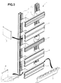
- the present invention relates to an electrical wiring frame for receiving electrical apparatus and their electrical wiring, this chassis comprising at least two vertical uprights arranged in parallel planes and at least one horizontal rail coupled to the vertical uprights by at least two stirrups of general shape in omega, the base of the stirrups determining the spacing of the horizontal rail relative to the vertical uprights, the interior space defined by these stirrups being used as a cable duct, the horizontal rail being provided with a standardized support intended for receive electrical appliances and at least one wire clamp comb arranged parallel to the support arranged to fix the electrical cables in position connected to said electrical devices.
- This type of wiring frame is well known and generally used in cabinets electric controls. It allows you to organize the wiring in an orderly fashion, clear and clean, the cables being positioned in the wire clamp combs and grouped in the side chutes formed by the omega-shaped stirrups. The wiring is greatly facilitated, as well as access to electrical devices and their cables.
- the known frames are produced by means of profiles assembled by screw-nut systems which require relatively long assembly times and a adapted tools. These assembly times are doubled when it is necessary to modify or adapt the position of the uprights and rails relative to each other. Otherwise, the distance between two consecutive horizontal rails is not infinitely adjustable being since the fixing holes are provided at regular intervals. It is therefore not always possible to achieve an optimal installation of the electrical cabinet. Of more, the number of parts required to make this type of chassis is relatively high considering the multiple possible variants.
- the present invention proposes to improve the chassis currently known in proposing an assembly system which is fast, simple and without tools allowing significantly reduce costs and assembly times.
- this system allows you to modify and adapt the position of the parts one by one with respect to each other, to modify their spacings continuously, in particular by sliding relative to each other, and modulating the architecture of the chassis as required.
- the parts making up this chassis have been studied for adapt to different variants so as to limit their number and therefore the cost of manufacture of the assembly.
- a chassis as defined in the preamble and characterized in that assembling the stirrups on the vertical uprights, the horizontal rail on the stirrups, the support and wire clamp comb on the horizontal rail is an assembly by interlocking and locking, removable, the elements to be joined together comprising respectively interlocking and locking means complementary arranged to cooperate with each other.
- These complementary means of interlocking and locking can be arranged to cooperate with each other by bringing said elements together in a movement of translation perpendicular to said elements and / or according to a rotational movement.
- the vertical post is formed of a profile, one side of which has a rounded pivot on one of the edges and on the other edge a groove.
- This vertical upright can have a general section substantially square, symmetrical with respect to a median plane parallel to said side provided with pivot and groove.
- the stirrup comprises, on its branch arranged with the side of the vertical upright, an external projection forming a rounded hook arranged to fit on the pivot provided on said vertical upright and a free end curved outwards forming an elastic tongue provided with a nose arranged to lock in the groove provided on said vertical upright by interlocking after rotation of the stirrup around said pivot, the spacing between the hook and the nose being less than or equal to the distance between the pivot and the groove, the stirrup and / or the vertical upright comprising, in the nesting zone, reliefs arranged for form stops.
- the stirrup advantageously has on its branch arranged on the side of the upright vertical at least one hole for receiving a sliding mounted fixing member in a groove provided in the vertical upright and arranged to lock the position of said stirrup.
- This stirrup also has, on its branch arranged on the side of the horizontal rail, a free end bent outwards, forming an angle of about 90 ° with its branch and provided with a groove.
- the horizontal rail is formed of a profile comprising on the rear face a longitudinal C-shaped groove, the free end of one of the branches being curved and carrying a bead arranged to fit on a first edge of the corresponding branch of said stirrup and the free end of the other branch forming a elastic tongue provided with a nose arranged to lock on the second edge of the corresponding branch of said bracket by fitting after rotation of said rail horizontal around said first edge, the spacing between the two branches of the C-shaped groove being at most equal to the width of the stirrup branch, the stirrup and / or the horizontal rail comprising, in the nesting zone, reliefs arranged to form stops.
- This horizontal rail also comprises on the front face a inverted T-shaped longitudinal groove.
- the support is formed of a profile and comprises in rear side two elastic hooking lugs and a boss, the lugs being arranged to fit into the T-shaped groove provided in the front face of the horizontal rail after a rotational movement around the boss bearing on said rail, the end of one of the legs being curved to press on the bottom of the groove and the end of the other tab having a hook to lock at the back of the corresponding free edge of said groove, the external distance defined by the two tabs being at least equal to the spacing between the two free edges of the groove and the distance between the boss and the hook of the tab being at most equal to the thickness of said free edge.
- the horizontal rail comprises, on its longitudinal edges, at least one U-shaped longitudinal groove with at least one recess longitudinal in one of its branches and the wire clamp comb has a foot attachment fitted with two elastic tabs, one of which carries a notch intended to lock in the longitudinal recess provided in said U-shaped groove by fitting of the foot after a translation of the wire clamp comb towards the rail horizontal.
- This wire clip comb preferably has a rear extension terminated by a heel intended to fit on the rear part of the horizontal rail the spacing between the heel and the attachment foot being less than or equal to the width of said rail in the nesting area.
- the wire clamp comb also has a plurality of teeth parallel to each other, each tooth having on its flanks at least one socket forming between two teeth consecutive housing to receive and hold in position an electric cable.
- the chassis comprises an insulating cover intended to cover at least partially said stirrup and comprising at least one large branch coupled to the branch arranged on the side of the vertical upright and provided on its free end of a groove.
- This chassis may also include at least one cover arranged to cover the gap between two frames arranged side by side, said cover comprising on its longitudinal edges at least one groove arranged to fit onto the corresponding free ends of the stirrup arms and the insulating cover.
- this cover comprises, at least in a central zone, deformable longitudinal corrugations arranged to adapt the width of the cover at the interval between the two chassis and to make up for the difference in levels between the two chassis.
- the latter advantageously comprises at least a lateral flange comprising on its longitudinal edges at least one groove arranged to fit on the free ends of the corresponding branches of the bracket and the insulating cover.
- Vertical uprights, horizontal rails, brackets and supports can be produced by extrusion in a material chosen from the group comprising aluminum, aluminum alloy, stainless steel, steel, plastics.
- insulating covers, wire clamp combs, covers and flanges side can be made of a dielectric synthetic material.
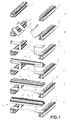
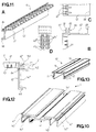
- the vertical upright 2 shown in Figures 3 and 4 has a flat profile or general square section, or of another suitable form. It includes, side, on one of the edges a rounded pivot 21 provided at the end of an angled arm 22 and on the other edge a groove 23.
- the vertical upright 2 is symmetrical with respect to its median plane parallel to the side provided with the pivot 21 and the groove 23. Consequently, this vertical upright 2 comprises a pivot 21 and a groove 23 on each side allowing it to be usable as well upright as left upright.
- the stirrup 3, represented by FIG. 5, comprises a profile in the shape of an omega allowing the mounting of the horizontal rails 4 on the vertical uprights 2 and perpendicular to these.
- the base 30 of the stirrup 3 defines the spacing of the rails 4 relative to the uprights 2 and the space defined between the branches 31, 32 of the bracket is used to store the harnesses of electric cables.
- This stirrup 3 comprises, on its branch 31 disposed on the side of the vertical upright 3, a projection outer forming a rounded hook 33 and a free end bent towards the outside forming a tongue 34 provided with a nose 35.
- the hook 33 is intended to fit on the pivot 21 and the nose 35 is intended to lock in the groove 23 after a rotational movement of the stirrup 3 around said pivot 21, thanks to the elastic deformation of the tongue 34.
- This rotational movement allowing the fitting and locking of the stirrup 3 on the vertical upright 2 is shown clearly by Figure 1B.
- the spacing provided between the hook 33 and the nose 35 is at most equal and preferably slightly less than that provided between the pivot 21 and the groove 23, stressing said interlocking.
- the bracket 3 and the vertical upright 2 have in their area interlocking reliefs formed by bosses or ribs respectively 36 and 24 arranged to form abutments bearing against one another, which put also under constraint said socket.
- the stirrup 3 also has two. opposite oblong holes 37, provided in branch 31 and intended to receive screws blocking (not shown) for blocking said stirrup in a fixed position on the vertical upright 2.
- the vertical upright 2 has a groove 25 in T shape overturned and arranged to receive the head of the locking screws or the nuts associated with these screws. This groove 25 being provided over the entire length of the upright vertical 2, it is easily understood that the stirrups 3 can be placed at any place along said amount. The edges of this groove 25 also form the stops 24 mentioned above.
- the stirrup 3 also has on its branch 32 disposed on the side of the horizontal rail 4 a free end 38 curved outwards and forming an angle of approximately 90 ° with its branch 32, provided with a groove 39.
- the design of this stirrup 3 allows it to be placed on the upright as well vertical left than on the vertical upright.
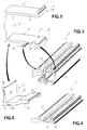
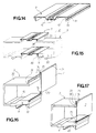
- the insulating cover 8 represented by FIG. 6, is intended to partially cover the bracket 3 for electrically isolating the horizontal rails 4 from the vertical uprights 2. It is made of a molded dielectric material and has an L-shape whose small branch 81 fits on base 30 and large branch 82 fits on base branch 31 of the stirrup 3. This large branch 82 has at its free end a groove 83 which can receive the lateral flange 7 or the cover 9 as detailed more far.
- This insulating cover 8 is extended laterally by flanges 84 provided with small pins 85 which fit into the rear of the stirrup 3 and maintain the cover 8 on the stirrup 3.
- the large branch 82 has a raised area 82 'to leave a free space in the area of the oblong holes 37 for the head of the fixing screws or the nuts associated with these screws.
- the horizontal rail 4 represented by FIGS. 7, 8 and 10, comprises, on the rear face, a C-shaped groove 41 intended to receive between its branches 42, 43, the branch 32 of the stirrup 3.
- the free end of its branch 42 is curved and has a bead 44 and the free end of its branch 43 forms a tongue provided with a nose 45.
- the spacing provided between the branches 42 and 43 of the groove 41 is at most equal and preferably slightly less than the width of the branch 32 stressing said socket.
- bosses 46 are provided in the bottom of this groove 41 to form abutments bearing against the branch 32 also putting under stress said interlocking.
- This horizontal rail 4 has on its front face a groove 141 in inverted T shape, parallel to the C-shaped groove 41, these grooves being arranged substantially back to back.
- This groove 141 is intended to receive the support 5, the free edges 142 and 143 of the T-shaped groove having a chamfer 144 intended to facilitate the fitting of said support 5.
- the longitudinal edges of the rail horizontal 8 also have a U-shaped groove 145, the opening of which is substantially perpendicular to those of grooves 41 and 141, groove 145 comprising at least on one of its branches a longitudinal recess 146 and designed to receive a wire clamp comb for holding cables in position electrical devices connected to said electrical devices carried by the support 5.
- This rail horizontal 8 can have variable widths according to needs while being compatible with the other profiles, the grooves 41, 141 and 145 remaining identical.
- the horizontal rail 8 of FIG. 8 has an average width while that of Figures 7 and 10 have a width almost double that of the rail of Figure 8. In this case, the horizontal rail 8 has longitudinal free edges 147 folded backwards substantially parallel to the branches 42 and 43 of the groove 41 in C shape.
- This horizontal rail 4 also has two grooves on the front parallel plates 47 arranged on either side of the groove 141 and arranged for receive identification labels intended to identify the electrical equipment worn by chassis 1.
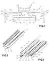
- the support 5 with reference to FIG. 9, comprises a standardized U-shaped profile and provided on the rear face with two hooking lugs 51, 52 arranged to be housed in the inverted T-shaped groove 141 provided in the front face of the rail horizontal 4.
- the tab 51 is longer than the tab 52 and its free end curved is intended to bear on the bottom of the groove 141.
- the tab 52 has at its free end a hook arranged to lock at the rear of the free edge 143 corresponding to the groove 141.
- This support 5 also has a longitudinal boss 53 parallel to lug 52 and arranged to press on the face outside of the free edge 143. The interval between the boss 53 and the hook the tab 52 is at most equal to the thickness of said free edge 143 so as to put under constrain said nesting.
- the support 5 is fitted into the groove 141 of the rail horizontal 4 by a rotational movement around the point or the support line formed by the boss 53 bearing on the rail 4 until the tab 52 is locked the rear of the free edge 143, the end of the tab 51 coming to bear on the bottom of the groove 141 to stabilize the position of the support 5 horizontally relative to said rail 4.
- the rounded and bevelled shape respectively of the free ends of the legs attachment 51, 52 as well as the chamfer 144 provided on the free edges 142, 143 of said groove 141 facilitate the introduction of the hooking lugs 51, 52.
- the external spacing defined by the tabs of attachment 51 and 52 is at least equal and preferably slightly greater than the spacing between the two free edges 142, 143 of the groove 141 putting under constrain said nesting.
- the front face of this support 5 is standardized and known skilled in the art since all types of electrical apparatus intended for be installed in an electrical cabinet have forms on the back complementary arranged to cooperate with said support 5.
- the wire clamp comb 6 is represented by FIGS. 11 A to D and 12.
- This comb 6 has a plurality of teeth 61 parallel and spaced at regular intervals integral with a longitudinal body 62.
- Each tooth 61 bears on its flanks at least one and preferably three notches 63, a first notch provided at the base and two others provided on the height of the tooth. These notches define between two teeth consecutive housings to receive electric cables 63 'maintained by pinching.
- This comb 6 comprises a hooking foot 64 arranged to be housed in the groove 145 in the form of a U provided in the horizontal rail 4, by fitting after a translation of the comb 6 towards the horizontal rail 4 substantially perpendicularly to said groove 145.
- This attachment foot 64 which can be longitudinal or under the form of regularly distributed nipples, has two parallel tabs 65, 66 one of which carries a notch 67 intended to fit into the corresponding recess 146 provided in groove 145, thus locking this assembly.
- the body 62 of the comb 6 extends backwards and ends with a heel 68 disposed substantially at an angle straight and intended to fit on one of the longitudinal edges 147 of the horizontal rail 4, as illustrated in FIG. 12, or on the branches 42, 43 of said horizontal rail 4 if it has a smaller width.
- the distance between the foot 64 and the heel 68 is at most equal and preferably slightly less than the width of the free edge 147 or branches 42, 43 stressing said socket.
- a cover 10, shown in FIG. 13, is provided for coupling two wire clamp combs 6 superimposed to avoid free intervals.
- This cover 10 comprises a profile in U-shaped whose branches 11, 12 are terminated by locking noses 13 arranged to fit and lock on the free end of the teeth 61 opposite.
- the base 14 of the cover 10 extends laterally beyond the branches 11, 12 forming a stop which presses on the rear of said teeth 61, ending aesthetically the assembly between two combs 6.
- a flat groove 15 is provided on the base 14 of the cover 10 and allows to receive identification labels to identify the devices electric carried by said chassis 1.
- a cover 9, represented by FIGS. 14 and 15, makes it possible to aesthetically connect two consecutive frames 1 by closing the empty intervals provided between them.
- This cover 9 has on its free longitudinal edges a groove 91 and a tab hook 92 substantially perpendicular to the latter, provided with a rib 93 longitudinal.
- a first cover 9 is fitted on the free ends of the large branches 82 of the insulating covers 8 and a second cover 9 is fitted on the free curved ends 38 of branches 32 of stirrups 3 by a translation of covers in the direction of the insulating covers 8 and the stirrups 3 respectively.
- first assembly the groove 91 fits into the groove 83 and the rib 93 fits at the back of this groove thus locking this assembly thanks to the elasticity of the fastening tab 92.
- the groove 91 fits on the edge of the free end 38 and the rib 93 fits in the groove 39 thus locking this assembly thanks to the elasticity of the hooking lug 92.
- This cover 9 has longitudinal corrugations 94 in a central zone and deformable to adapt the width of the cover 9 to the gap between the two chassis 1 consecutive and even make up for the difference in levels between these frame. It is made of a molded synthetic material allowing this permanent deformation and can of course extend over the entire height of the chassis 1.
- the lateral flange 7, represented by FIGS. 16 and 17, makes it possible to close the sides of the chassis 1 to obtain a finished aesthetic chassis.
- This lateral flange 7 comprises a plate made of substantially rectangular molded synthetic material, provided with two longitudinal free edges 71, 72. It has on the free edge 71 a longitudinal groove 73 and a rib 74 intended to fit respectively on the free curved edge 38 and in the groove 39 of the branch 32 of the stirrup 3. It comprises, on the free edge 72, a longitudinal tab 75 folded in L intended for fit into the groove 83 provided on the insulating cover 8.
- the installation of this lateral flange 7 is produced by translation of the flange in the direction of the stirrup and nesting of the flange in the grooves thanks to its elasticity. This flange 7 may well sure to extend over the entire height of the chassis 1.
- the chassis are designed to be assembled easily without tools while ensuring high rigidity of assembly and a reliable and durable support for electrical appliances, to adapt and modulate to the specific needs of each user, to also be able to easily disassemble in case of modification or complement, to slide relative to each other and allow their precise positioning, etc.
- All the profiles making up the vertical uprights 2, the brackets 3, the horizontal rails 4 and the supports 5 are advantageously made of extruded aluminum. However, they could also be produced by extrusion in steel, stainless steel, aluminum alloy, synthetic material.
- the other parts such that the wire clamp combs 6, the side flanges 7, the insulating covers 8 and the covers 9 are advantageously made of molded synthetic material.
Landscapes
- Engineering & Computer Science (AREA)
- Power Engineering (AREA)
- Installation Of Indoor Wiring (AREA)
- Insulation, Fastening Of Motor, Generator Windings (AREA)
- Insulated Conductors (AREA)
- Non-Portable Lighting Devices Or Systems Thereof (AREA)
- Connector Housings Or Holding Contact Members (AREA)
- Coupling Device And Connection With Printed Circuit (AREA)
- Manufacturing Of Printed Wiring (AREA)
- Liquid Crystal (AREA)
- Connections Arranged To Contact A Plurality Of Conductors (AREA)
- Patch Boards (AREA)
- Casings For Electric Apparatus (AREA)
- Mounting Of Printed Circuit Boards And The Like (AREA)
- Synchronisation In Digital Transmission Systems (AREA)
Claims (20)
- Rahmen (1) für elektrische Verdrahtung zur Aufnahme von Elektrogeräten und deren elektrischer Verdrahtung, wobei der Rahmen mindestens zwei in parallelen Ebenen angeordnete Vertikalträger (2) und mindestens eine Horizontalschiene (4) aufweist, die mit den Vertikalträgern mittels mindestens zwei im allgemeinen omegaförmigen Bügeln (3) verbunden ist, wobei die Basis der Bügel den Abstand der Horizontalschiene zu den Vertikalträgern definiert und der durch diese Bügel definierte Innenraum als Kabelschacht verwendet wird, wobei die Horizontalschiene mit einem genormten Träger (5) zur Aufnahme der Elektrogeräte, und mit mindestens einer kammförmigen Drahtklemmplatte (6) versehen ist, die parallel zu dem Träger so angeordnet ist, daß sie die mit den Elektrogeräten verbundenen Elektrokabel in ihrer Position fixiert, dadurch gekennzeichnet, daß es sich bei der Montage der Bügel (3) auf den Vertikalträgern (2), der Horizontalschiene (4) auf den Bügeln, des Trägers (5) und der kammförmigen Drahtklemmplatte (6) auf der Horizontalschiene um eine demontierbare Montage durch Einpassen und Einrasten handelt, wobei die zu montierenden Elemente gegenseitig jeweils die ergänzenden Einpassungs- und Einrastmittel aufweisen, die so angeordnet sind, daß sie zusammenwirken.
- Rahmen nach Anspruch 1, dadurch gekennzeichnet, daß die ergänzenden Einpassungs- und Einrastmittel so angeordnet sind, daß sie zusammenwirken, indem die Elemente entsprechend einer senkrecht zu den Elementen verlaufenden Translationsbewegung angenähert werden.
- Rahmen nach Anspruch 1, dadurch gekennzeichnet, daß die ergänzenden Einpassungs- und Einrastmittel so angeordnet sind, daß sie zusammenwirken, indem die Elemente entsprechend einer Drehbewegung angenähert werden.
- Rahmen nach Anspruch 3, dadurch gekennzeichnet, daß der Vertikalträger (2) aus einem Profilstahl ausgebildet ist, dessen eine Seite auf einem der Ränder eine runde Drehachse (21), und auf dem anderen Rand eine Nut (23) aufweist.
- Rahmen nach Anspruch 4, dadurch gekennzeichnet, daß der Vertikalträger (2) einen im allgemeinen praktisch quadratischen Querschnitt aufweist, der im Verhältnis zu einer mittleren Ebene symmetrisch ist, die zu der mit der Drehachse und -15- Nut versehenen Seite parallel verläuft.
- Rahmen nach Anspruch 4, dadurch gekennzeichnet, daß der Bügel (3) auf seinem auf der Seite des Vertikalträgers (2) angeordneten Schenkel (31) einen Außenvorsprung aufweist, der einen Rundhaken (33) bildet und so angeordnet ist, daß er die auf dem Vertikalträger (2) vorgesehene Drehachse (21) umschließt, wobei ein freies äußerstes Ende nach außen umgebogen ist und eine elastische Lasche (34) bildet, die mit einer Nase (35) versehen ist, die so angeordnet ist, daß sie nach der Drehung des Bügels um die Drehachse durch Einpassung in der auf dem Vertikalträger vorgesehenen Nut (23) einrastet, wobei der Abstand zwischen dem Haken und der Nase kleiner oder gleich dem Abstand zwischen der Drehachse und der Nut ist, wobei der Bügel und/oder der Vertikalträger in der Einpassungszone Reliefs (24, 36) aufweist, die so angeordnet sind, daß sie Anschläge bilden.
- Rahmen nach Anspruch 6, dadurch gekennzeichnet, daß der Bügel (3) auf seinem auf der Seite des Vertikalträgers (2) angeordneten Schenkel (31) mindestens ein Loch (37) aufweist, das zur Aufnahme eines Befestigungsbauteils bestimmt ist, das in einer in dem Vertikalträger (2) vorgesehenen Nut (25) gleitend montiert und so angeordnet ist, daß es die Position des Bügels arretiert.
- Rahmen nach Anspruch 6, dadurch gekennzeichnet, daß der Bügel (3) auf seinem auf der Seite der Horizontalschiene (4) angeordneten Schenkel (32) ein nach außen umgebogenes freies äußerstes Ende (38) aufweist, das einen Winkel von ungefähr 90° mit dessen Schenkel bildet und mit einer Nut (39) versehen ist.
- Rahmen nach Anspruch 8, dadurch gekennzeichnet, daß die Horizontalschiene (4) aus einem Profilstahl ausgebildet ist, der auf der Rückseite eine C-förmige Längsnut (41) aufweist, wobei das freie äußerste Ende eines der Schenkel (42) umgebogen ist und einen Wulst (44) trägt, der so angeordnet ist, daß er einen ersten Rand des entsprechenden Schenkels (32) des Bügels umschließt, und das freie äußerste Ende des anderen Schenkels (43) eine mit einer Nase (45) versehene elastische Lasche bildet, die so angeordnet ist, daß sie auf dem zweiten Rand des entsprechenden Schenkels (32) des Bügels nach der Drehung der Horizontalschiene um den ersten Rand durch Einpassung einrastet, wobei der Abstand zwischen den zwei Schenkeln der C-förmigen Nut höchstens gleich der Breite des Schenkels des Bügels ist, wobei der Bügel und/oder die Horizontalschiene in der Einpassungszone Reliefs (46) aufweisen, die so angeordnet sind, daß sie Anschläge bilden.
- Rahmen nach Anspruch 9, dadurch gekennzeichnet, daß die Horizontalschiene (4) auf der Vorderseite eine Längsnut (141) in Form eines umgekehrten T aufweist.
- Rahmen nach Anspruch 10, dadurch gekennzeichnet, daß der Träger (5) aus einem Profilstahl ausgebildet ist und auf der Rückseite zwei elastische Einhängklauen (51,52) und einen Buckel (53) aufweist, wobei die Klauen (51,52) so angeordnet sind, daß sie in der T-förmigen Nut (141), die in der Vorderseite der Horizontalschiene (4) vorgesehen ist, nach einer Drehbewegung um den Wulst (53) unter Abstützung auf der Schiene (4) einrasten, wobei das äußerste Ende einer der Klauen (51) umgebogen ist, um sich auf dem Boden der Nut (141) abzustützen und das äußerste Ende der anderen Klaue (52) einen Haken aufweist, um hinten an dem entsprechenden freien Rand (143) der Nut (141) einzurasten, wobei der durch die zwei Klauen (51,52) definierte Außenabstand mindestens gleich dem Abstand zwischen den zwei freien Rändern (142,143) der Nut (141), und der Abstand zwischen dem Buckel (53) der Klaue (52) höchstens gleich der Dicke des freien Randes (143) ist.
- Rahmen nach Anspruch 2 und 9, dadurch gekennzeichnet, daß die Horizontalschiene (4) auf ihren Längsrändern mindestens eine U-förmige Längsnut (145) aufweist, die mit mindestens einer Längsaussparung (146) in einer ihrer Schenkel versehen ist, und die kammförmige Drahtklemmplatte (6) einen mit zwei elastischen Laschen (65,66) versehenen Einhängfuß (64) aufweist, wobei eine davon eine Rastkerbe (67) trägt, die dazu bestimmt ist, durch Einpassung des Fußes nach einer Translationsbewegung des kammförmigen Elementes in Richtung der Horizontalschiene in der Längseinsparung (146) einzurasten, die in der U-förmigen Nut vorgesehen ist.
- Rahmen nach Anspruch 12, dadurch gekennzeichnet, daß die kammförmige Drahtklemmplatte (6) eine hintere Verlängerung (62) aufweist, die durch einen Abschnitt (68) abgeschlossen ist, der dazu bestimmt ist, den hinteren Teil der Horizontalschiene (4) zu umschließen, wobei der Abstand zwischen dem Absatz (68) und dem Einhängfuß (64) kleiner oder gleich der Breite der Schiene in der Einpassungszone ist.
- Rahmen nach Anspruch 13, dadurch gekennzeichnet, daß die kammförmige Drahtklemmplatte (6) eine Vielzahl zueinander parallel angeordneter Zähne (61) aufweist, wobei jeder Zahn auf seinen Flanken mindestens einen Einschnitt (63) aufweist, der zwischen zwei aufeinanderfolgenden Zähnen einen Sitz zur Aufnahme und zum Halten eines Elektrokabels (63') in seiner Position bildet.
- Rahmen nach Anspruch 8, dadurch gekennzeichnet, daß er eine Isolationsabdeckung (8) aufweist, die dazu bestimmt ist, mindestens teilweise den Bügel (3) abzudecken und mindestens einen großen Schenkel (82) aufweist, der mit dem auf der Seite des Vertikalträgers (2) angeordneten Schenkel (31) verbunden, und auf seinem freien äußersten Ende mit einer Nut (83) versehen ist.
- Rahmen nach Anspruch 15, dadurch gekennzeichnet, daß er mindestens einen Deckel (9) aufweist, der so angeordnet ist, daß er den zwischen zwei Seite an Seite angeordneten Rahmen (1) vorhandenen Abstand überdeckt, wobei der Deckel auf seinen Längsrändern mindestens eine Nut (91) aufweist, die so angeordnet ist, daß sie die entsprechenden freien äußersten Enden der Schenkel (32, 82) des Bügels (3) und der Isolationsabdeckung (8) umschließt.
- Rahmen nach Anspruch 16, dadurch gekennzeichnet, daß der Deckel (9) mindestens in einer Zentralzone verformbare Längswellen (94) aufweist, die so angeordnet sind, daß sie die Länge des Deckels (9) an den zwischen den beiden Rahmen (1) vorhandenen Abstand anpassen, und um die Niveauunterschiede zwischen den zwei Rahmen auszugleichen.
- Rahmen nach Anspruch 15, dadurch gekennzeichnet, daß er mindestens eine Seitenblende (7) aufweist, die angeordnet ist, um die Seiten des Rahmens (1) zu schließen, wobei die Blende auf ihren Längsrändern (71,72) mindestens eine Nut (73) aufweist, die so angeordnet ist, daß sie die freien äußersten Enden der entsprechenden Schenkel (32,82) des Bügels (3) und der Isolationsabdeckung (8) umschließt.
- Rahmen nach einem der vorangegangenen Ansprüche, dadurch gekennzeichnet, daß die Vertikalträger (2), die Horizontalschienen (4), die Bügel (3) und die Träger (5) durch Extrudieren eines aus der Gruppe ausgewählten Materials hergestellt sind, die aus Aluminium, Aluminiumlegierungen, rostfreiem Stahl, Stahl, synthetischen Materialien besteht.
- Rahmen nach einem der vorangegangenen Ansprüche, dadurch gekennzeichnet, daß die Isolationsabdeckungen (8), die kammförmigen Drahtklemmplatten (6), die Deckel (9) und die Seitenblenden (7) aus einem dielektrischen synthetischen Material ausgeführt sind.
Applications Claiming Priority (3)
| Application Number | Priority Date | Filing Date | Title |
|---|---|---|---|
| FR9704169 | 1997-03-27 | ||
| FR9704169A FR2761569B1 (fr) | 1997-03-27 | 1997-03-27 | Chassis de cablage electrique |
| PCT/FR1998/000599 WO1998044609A1 (fr) | 1997-03-27 | 1998-03-25 | Chassis de cablage electrique |
Publications (2)
| Publication Number | Publication Date |
|---|---|
| EP0970552A1 EP0970552A1 (de) | 2000-01-12 |
| EP0970552B1 true EP0970552B1 (de) | 2001-10-10 |
Family
ID=9505554
Family Applications (1)
| Application Number | Title | Priority Date | Filing Date |
|---|---|---|---|
| EP98917228A Expired - Lifetime EP0970552B1 (de) | 1997-03-27 | 1998-03-25 | Rahmen für elektrische verdrahtung |
Country Status (13)
| Country | Link |
|---|---|
| US (1) | US6246004B1 (de) |
| EP (1) | EP0970552B1 (de) |
| JP (1) | JP2001516560A (de) |
| CN (1) | CN1159812C (de) |
| AT (1) | ATE206848T1 (de) |
| AU (1) | AU7050798A (de) |
| BR (1) | BR9809059B1 (de) |
| CA (1) | CA2285103C (de) |
| DE (1) | DE69801988T2 (de) |
| EA (1) | EA001300B1 (de) |
| ES (1) | ES2165674T3 (de) |
| FR (1) | FR2761569B1 (de) |
| WO (1) | WO1998044609A1 (de) |
Cited By (1)
| Publication number | Priority date | Publication date | Assignee | Title |
|---|---|---|---|---|
| WO2014015988A1 (de) * | 2012-07-25 | 2014-01-30 | Friedrich Lütze GmbH | Montagesystem für die anordnung von beispielsweise elektrischen einrichtungen insbesondere in schaltschränken |
Families Citing this family (33)
| Publication number | Priority date | Publication date | Assignee | Title |
|---|---|---|---|---|
| DE19935445C1 (de) * | 1999-07-28 | 2001-03-22 | Hager Electro Gmbh | Baustein für den Einbau in ein Gehäuse eines elektrischen Verteilers |
| DE19961343A1 (de) * | 1999-12-17 | 2001-06-21 | Schenck Pegasus Gmbh | Träger für elektrische und eletromechanische Baueinheiten |
| KR100378341B1 (ko) * | 2000-08-07 | 2003-03-29 | 유도실업주식회사 | 주입노즐의 히터선 고정홈을 가지는 상부금형 |
| US6515224B1 (en) | 2000-11-21 | 2003-02-04 | Equinix, Inc. | Cascading cable tray system with pre-fabricated support structure |
| JP4592047B2 (ja) * | 2001-07-26 | 2010-12-01 | 河村電器産業株式会社 | 機器収納用ラック |
| DE10204934A1 (de) * | 2002-02-07 | 2003-09-04 | Abb Patent Gmbh | Anschluß- oder Verteilvorrichtung für elektrische Installationsgeräte |
| FR2846158B1 (fr) * | 2002-10-22 | 2004-12-24 | Schneider Electric Ind Sas | Chassis pour appareillage electrique |
| DE10314937B4 (de) * | 2003-04-02 | 2019-10-10 | Friedrich Lütze GmbH | Profilleiste aus Kunststoff zum Halten einer Vielzahl von elektrischen Leitungen |
| DE10325936A1 (de) * | 2003-06-07 | 2004-12-23 | Hager Electro Gmbh | Verteiler, insbesondere Kleinverteiler |
| ITMI20050709A1 (it) * | 2005-04-20 | 2006-10-21 | Coepte S R L | Dispositivo per il supporto di componenti elettrici e di accessori di cablaggio ad elevata praticita' di impiego |
| ITMI20050708A1 (it) * | 2005-04-20 | 2006-10-21 | Coepte S R L | Profilato per il supporto di componenti elettrici ad elevata versatilita' di impiego |
| DE102005032872B4 (de) * | 2005-07-14 | 2007-12-06 | Adc Gmbh | Modulare Gehäusewand für Telekommunikationseinrichtungen |
| USD562327S1 (en) * | 2006-01-23 | 2008-02-19 | Nextronics Engineering Corp. | Cross rail |
| FR2926409B1 (fr) * | 2008-01-14 | 2010-02-05 | Inovac | Goulotte electrique a moyens de freinage d'appareillages electriques ou d'accessoires rapportes sur son socle |
| EP2124302B1 (de) * | 2008-05-21 | 2010-01-06 | Klaus Wurmhöringer | Rahmengestell für eine Prüfzelle |
| CN102149263B (zh) * | 2011-05-04 | 2013-07-31 | 株洲南车时代电气股份有限公司 | 一种机箱布线装置及其方法 |
| FR2979758B1 (fr) * | 2011-09-06 | 2014-05-09 | Schneider Electric Ind Sas | Dispositif de rangement des conducteurs de cablage des appareillages dans une armoire electrique equipee de rails de montage desdits appareillages |
| USD687782S1 (en) * | 2012-03-16 | 2013-08-13 | Enduro Composites, Inc. | Conduit tray |
| USD696206S1 (en) * | 2012-03-16 | 2013-12-24 | Enduro Composites, Inc. | Brace member |
| US9365092B2 (en) * | 2012-03-30 | 2016-06-14 | Toyota Motor Engineering & Manufacturing North America, Inc. | Console duct hook and snap feature |
| DE102012014979A1 (de) * | 2012-07-25 | 2014-05-15 | Friedrich Lütze GmbH | Montagesystem für die Anordnung von beispielsweise elektrischen Einrichtungen insbesondere in Schaltschränken |
| DE102012014980A1 (de) * | 2012-07-25 | 2014-05-15 | Friedrich Lütze GmbH | Montagesystem für die Anordnung von beispielsweise elektrischen Einrichtungen insbesondere in Schaltschränken |
| FR3023424B1 (fr) * | 2014-07-03 | 2016-07-22 | Abb France | Montage d’un systeme de demarrage sur une pluralite de rails de fixation |
| CN104264982B (zh) * | 2014-10-09 | 2016-08-17 | 深圳汇林达科技有限公司 | 一种散拼早拆建筑模板体系及其搭建方法 |
| CN106358406A (zh) * | 2016-11-17 | 2017-01-25 | 广州市科迅电子科技有限公司 | 一种垂直配线架及装有该垂直配线架的机柜 |
| DE102017108523B4 (de) * | 2017-04-21 | 2019-01-03 | Rittal Gmbh & Co. Kg | Montageplattenanordnung für einen Schaltschrank |
| DE102017130232A1 (de) * | 2017-12-15 | 2019-06-19 | Abb Schweiz Ag | Anordnung, umfassend eine Schiene und eine Abdeckung |
| US10799041B1 (en) * | 2019-03-26 | 2020-10-13 | Tag Hardware Systems Ltd. | Wall mounted organizer rack |
| CN109861153B (zh) * | 2019-04-15 | 2024-09-27 | 重庆浙升科技有限公司 | 一种用于电缆沟的组装盖板 |
| CN111541165B (zh) * | 2020-05-11 | 2021-06-29 | 吉林盛辉电气有限公司 | 一种免排线的配电箱 |
| CN115441350A (zh) * | 2022-09-30 | 2022-12-06 | 华翔翔能科技股份有限公司 | 一种充气柜用可调节电缆支撑件 |
| CN118040512B (zh) * | 2024-04-11 | 2024-06-04 | 宝利阳光(福建)新能源有限公司 | 一种智能式无功补偿配电箱 |
| CN121216325B (zh) * | 2025-11-26 | 2026-03-03 | 四川铁道职业学院 | 一种电力电缆铺设用辅助定位分隔装置 |
Family Cites Families (5)
| Publication number | Priority date | Publication date | Assignee | Title |
|---|---|---|---|---|
| DE2330166C3 (de) * | 1973-06-14 | 1980-04-17 | Friedrich 7050 Waiblingen Luetze | Bausatz zur Schnellmontage von Schalt- und Steuerungstafeln |
| DE7824434U1 (de) * | 1978-08-16 | 1978-12-21 | Friedrich Luetze Gmbh & Co, 7056 Weinstadt | Montagebügel aus Profilstahl für einen Verdrahtungsrahmen |
| FR2633784B1 (fr) * | 1988-07-04 | 1991-04-26 | Telemecanique Electrique | Dispositif de support pour appareils electriques |
| FR2682229B1 (fr) * | 1991-10-04 | 1994-01-14 | Fournie Grospaud | Goulotte pour filerie pour le raccordement, notamment sur un bornier, de fils d'un cable electrique. |
| US5982610A (en) * | 1998-05-27 | 1999-11-09 | Reltec Corporation | Multisided communication distribution cabinet having adjustable tie rod |
-
1997
- 1997-03-27 FR FR9704169A patent/FR2761569B1/fr not_active Expired - Fee Related
-
1998
- 1998-03-25 JP JP54122498A patent/JP2001516560A/ja not_active Ceased
- 1998-03-25 WO PCT/FR1998/000599 patent/WO1998044609A1/fr not_active Ceased
- 1998-03-25 EP EP98917228A patent/EP0970552B1/de not_active Expired - Lifetime
- 1998-03-25 AU AU70507/98A patent/AU7050798A/en not_active Abandoned
- 1998-03-25 DE DE69801988T patent/DE69801988T2/de not_active Expired - Lifetime
- 1998-03-25 CA CA002285103A patent/CA2285103C/fr not_active Expired - Lifetime
- 1998-03-25 CN CNB988037041A patent/CN1159812C/zh not_active Expired - Fee Related
- 1998-03-25 ES ES98917228T patent/ES2165674T3/es not_active Expired - Lifetime
- 1998-03-25 EA EA199900870A patent/EA001300B1/ru not_active IP Right Cessation
- 1998-03-25 US US09/402,043 patent/US6246004B1/en not_active Expired - Lifetime
- 1998-03-25 BR BRPI9809059-3A patent/BR9809059B1/pt not_active IP Right Cessation
- 1998-03-25 AT AT98917228T patent/ATE206848T1/de active
Cited By (2)
| Publication number | Priority date | Publication date | Assignee | Title |
|---|---|---|---|---|
| WO2014015988A1 (de) * | 2012-07-25 | 2014-01-30 | Friedrich Lütze GmbH | Montagesystem für die anordnung von beispielsweise elektrischen einrichtungen insbesondere in schaltschränken |
| US9515458B2 (en) | 2012-07-25 | 2016-12-06 | Friedrich Luetze Gmbh | Mounting system for arranging electric devices, for example, especially in switchgear cabinets |
Also Published As
| Publication number | Publication date |
|---|---|
| WO1998044609A1 (fr) | 1998-10-08 |
| EA001300B1 (ru) | 2000-12-25 |
| FR2761569B1 (fr) | 1999-06-11 |
| FR2761569A1 (fr) | 1998-10-02 |
| BR9809059A (pt) | 2000-08-01 |
| JP2001516560A (ja) | 2001-09-25 |
| CA2285103A1 (fr) | 1998-10-08 |
| CA2285103C (fr) | 2008-11-18 |
| AU7050798A (en) | 1998-10-22 |
| EA199900870A1 (ru) | 2000-04-24 |
| BR9809059B1 (pt) | 2013-06-04 |
| EP0970552A1 (de) | 2000-01-12 |
| DE69801988D1 (de) | 2001-11-15 |
| DE69801988T2 (de) | 2002-05-29 |
| US6246004B1 (en) | 2001-06-12 |
| ATE206848T1 (de) | 2001-10-15 |
| CN1159812C (zh) | 2004-07-28 |
| CN1251220A (zh) | 2000-04-19 |
| ES2165674T3 (es) | 2002-03-16 |
Similar Documents
| Publication | Publication Date | Title |
|---|---|---|
| EP0970552B1 (de) | Rahmen für elektrische verdrahtung | |
| EP0169289B1 (de) | Zubehör zur Befestigung eines Artikels an einem Träger | |
| FR2530275A3 (fr) | Revetement de sol en elements assembles pour l'escrime et les sports similaires | |
| FR2768867A1 (fr) | Systeme de confinement de fils destine a etre monte sur une structure de mur | |
| FR3020514A1 (fr) | Appareillage electrique a assemblage securise | |
| EP0473481B1 (de) | Befestigungsgehäuse mit variablem Achsabstand für elektrisches Gerät | |
| EP0785606A1 (de) | Vorrichtung zum Befestigen eines elektrischen Gerätes | |
| FR2665044A1 (fr) | Dispositif porte-etiquette pour repartiteur telephonique. | |
| EP0762585B1 (de) | Befestigungszubehör zur Montage an ein Gestell, insbesondere für Befestigung von elektrischen Apparaten | |
| FR2727186A1 (fr) | Habillage pour chemin de cables en fils, et chemin de cables comportant un tel habillage | |
| EP1376807B1 (de) | Schnellbefestigungsvorrichtung für Wandkabelkanal | |
| FR2634326A1 (fr) | Coffret de repartition | |
| EP4404403A1 (de) | Zubehör zur montage von fassungen für elektrische und/oder elektronische geräte in einer profilleitung und damit ausgestattete mehrfachgeräte- oder elektrorinne | |
| FR2755310A1 (fr) | Agrafe de retenue pour goulotte, et goulotte equipee d'une telle agrafe de retenue | |
| EP1320163A1 (de) | Immobilisierungszubehör für ein elektrisches Installationsgerät mit Direktschnappverbindung in einem Kabelrinnesockel | |
| FR2786616A1 (fr) | Support pour appareillage a disposer le long d'une goulotte avec auvent en plusieurs parties | |
| BE1005508A3 (fr) | Coffret de branchement residentiel. | |
| EP1211773B1 (de) | Träger für ein Gerät, inbesondere für ein elektrisches Gerät, zur Befestigung auf einem Kabelkanalkörper | |
| EP0473482B1 (de) | Befestigungsgehäuse für elektrisches Gerät | |
| FR3104840A1 (fr) | Support d’appareillage à monter dans une paroi de faible épaisseur et module d’appareillage comportant un tel support | |
| FR2888682A1 (fr) | Accessoire a longueur variable pour goulotte electrique et ensemble electrique comprenant une goulotte electrique ainsi qu'un tel accessoire | |
| FR2589291A1 (fr) | Bati de raccordement | |
| EP0459860A2 (de) | Modulklemmleiste für elektrische Verbindungen | |
| FR2728401A1 (fr) | Barrette de maintien pour retenir des cables dans une goulotte | |
| EP0848470B1 (de) | Kanal für elektrische Anlage und Verwendung |
Legal Events
| Date | Code | Title | Description |
|---|---|---|---|
| PUAI | Public reference made under article 153(3) epc to a published international application that has entered the european phase |
Free format text: ORIGINAL CODE: 0009012 |
|
| 17P | Request for examination filed |
Effective date: 19990917 |
|
| AK | Designated contracting states |
Kind code of ref document: A1 Designated state(s): AT BE CH DE DK ES FI FR GB GR IE IT LI LU MC NL PT SE |
|
| 111L | Licence recorded |
Free format text: 20000520 0100 SATIE, SOCIETE ANONYME |
|
| GRAG | Despatch of communication of intention to grant |
Free format text: ORIGINAL CODE: EPIDOS AGRA |
|
| 17Q | First examination report despatched |
Effective date: 20001123 |
|
| GRAG | Despatch of communication of intention to grant |
Free format text: ORIGINAL CODE: EPIDOS AGRA |
|
| GRAH | Despatch of communication of intention to grant a patent |
Free format text: ORIGINAL CODE: EPIDOS IGRA |
|
| GRAH | Despatch of communication of intention to grant a patent |
Free format text: ORIGINAL CODE: EPIDOS IGRA |
|
| GRAA | (expected) grant |
Free format text: ORIGINAL CODE: 0009210 |
|
| AK | Designated contracting states |
Kind code of ref document: B1 Designated state(s): AT BE CH DE DK ES FI FR GB GR IE IT LI LU MC NL PT SE |
|
| PG25 | Lapsed in a contracting state [announced via postgrant information from national office to epo] |
Ref country code: NL Free format text: LAPSE BECAUSE OF FAILURE TO SUBMIT A TRANSLATION OF THE DESCRIPTION OR TO PAY THE FEE WITHIN THE PRESCRIBED TIME-LIMIT Effective date: 20011010 Ref country code: IE Free format text: LAPSE BECAUSE OF FAILURE TO SUBMIT A TRANSLATION OF THE DESCRIPTION OR TO PAY THE FEE WITHIN THE PRESCRIBED TIME-LIMIT Effective date: 20011010 Ref country code: FI Free format text: LAPSE BECAUSE OF FAILURE TO SUBMIT A TRANSLATION OF THE DESCRIPTION OR TO PAY THE FEE WITHIN THE PRESCRIBED TIME-LIMIT Effective date: 20011010 |
|
| REF | Corresponds to: |
Ref document number: 206848 Country of ref document: AT Date of ref document: 20011015 Kind code of ref document: T |
|
| REG | Reference to a national code |
Ref country code: CH Ref legal event code: EP |
|
| REG | Reference to a national code |
Ref country code: IE Ref legal event code: FG4D Free format text: FRENCH |
|
| REF | Corresponds to: |
Ref document number: 69801988 Country of ref document: DE Date of ref document: 20011115 |
|
| REG | Reference to a national code |
Ref country code: GB Ref legal event code: IF02 |
|
| PG25 | Lapsed in a contracting state [announced via postgrant information from national office to epo] |
Ref country code: SE Free format text: LAPSE BECAUSE OF FAILURE TO SUBMIT A TRANSLATION OF THE DESCRIPTION OR TO PAY THE FEE WITHIN THE PRESCRIBED TIME-LIMIT Effective date: 20020110 Ref country code: PT Free format text: LAPSE BECAUSE OF FAILURE TO SUBMIT A TRANSLATION OF THE DESCRIPTION OR TO PAY THE FEE WITHIN THE PRESCRIBED TIME-LIMIT Effective date: 20020110 Ref country code: DK Free format text: LAPSE BECAUSE OF FAILURE TO SUBMIT A TRANSLATION OF THE DESCRIPTION OR TO PAY THE FEE WITHIN THE PRESCRIBED TIME-LIMIT Effective date: 20020110 |
|
| PG25 | Lapsed in a contracting state [announced via postgrant information from national office to epo] |
Ref country code: GR Free format text: LAPSE BECAUSE OF FAILURE TO SUBMIT A TRANSLATION OF THE DESCRIPTION OR TO PAY THE FEE WITHIN THE PRESCRIBED TIME-LIMIT Effective date: 20020111 |
|
| GBT | Gb: translation of ep patent filed (gb section 77(6)(a)/1977) |
Effective date: 20020105 |
|
| REG | Reference to a national code |
Ref country code: CH Ref legal event code: NV Representative=s name: CABINET ROLAND NITHARDT CONSEILS EN PROPRIETE INDU |
|
| NLV1 | Nl: lapsed or annulled due to failure to fulfill the requirements of art. 29p and 29m of the patents act | ||
| REG | Reference to a national code |
Ref country code: ES Ref legal event code: FG2A Ref document number: 2165674 Country of ref document: ES Kind code of ref document: T3 |
|
| PG25 | Lapsed in a contracting state [announced via postgrant information from national office to epo] |
Ref country code: MC Free format text: LAPSE BECAUSE OF NON-PAYMENT OF DUE FEES Effective date: 20020325 Ref country code: LU Free format text: LAPSE BECAUSE OF NON-PAYMENT OF DUE FEES Effective date: 20020325 |
|
| REG | Reference to a national code |
Ref country code: IE Ref legal event code: FD4D |
|
| PLBE | No opposition filed within time limit |
Free format text: ORIGINAL CODE: 0009261 |
|
| STAA | Information on the status of an ep patent application or granted ep patent |
Free format text: STATUS: NO OPPOSITION FILED WITHIN TIME LIMIT |
|
| 26N | No opposition filed | ||
| REG | Reference to a national code |
Ref country code: FR Ref legal event code: CL |
|
| PGFP | Annual fee paid to national office [announced via postgrant information from national office to epo] |
Ref country code: GB Payment date: 20120328 Year of fee payment: 15 |
|
| PGFP | Annual fee paid to national office [announced via postgrant information from national office to epo] |
Ref country code: ES Payment date: 20120323 Year of fee payment: 15 Ref country code: AT Payment date: 20130327 Year of fee payment: 16 |
|
| PGFP | Annual fee paid to national office [announced via postgrant information from national office to epo] |
Ref country code: BE Payment date: 20130327 Year of fee payment: 16 |
|
| GBPC | Gb: european patent ceased through non-payment of renewal fee |
Effective date: 20130325 |
|
| PG25 | Lapsed in a contracting state [announced via postgrant information from national office to epo] |
Ref country code: GB Free format text: LAPSE BECAUSE OF NON-PAYMENT OF DUE FEES Effective date: 20130325 |
|
| REG | Reference to a national code |
Ref country code: ES Ref legal event code: FD2A Effective date: 20140606 |
|
| PG25 | Lapsed in a contracting state [announced via postgrant information from national office to epo] |
Ref country code: ES Free format text: LAPSE BECAUSE OF NON-PAYMENT OF DUE FEES Effective date: 20130326 |
|
| REG | Reference to a national code |
Ref country code: AT Ref legal event code: MM01 Ref document number: 206848 Country of ref document: AT Kind code of ref document: T Effective date: 20140325 |
|
| PG25 | Lapsed in a contracting state [announced via postgrant information from national office to epo] |
Ref country code: AT Free format text: LAPSE BECAUSE OF NON-PAYMENT OF DUE FEES Effective date: 20140325 |
|
| REG | Reference to a national code |
Ref country code: FR Ref legal event code: PLFP Year of fee payment: 19 |
|
| PG25 | Lapsed in a contracting state [announced via postgrant information from national office to epo] |
Ref country code: IT Free format text: LAPSE BECAUSE OF NON-PAYMENT OF DUE FEES Effective date: 20160325 |
|
| REG | Reference to a national code |
Ref country code: FR Ref legal event code: PLFP Year of fee payment: 20 |
|
| PGFP | Annual fee paid to national office [announced via postgrant information from national office to epo] |
Ref country code: DE Payment date: 20170324 Year of fee payment: 20 Ref country code: CH Payment date: 20170331 Year of fee payment: 20 |
|
| PG25 | Lapsed in a contracting state [announced via postgrant information from national office to epo] |
Ref country code: BE Free format text: LAPSE BECAUSE OF NON-PAYMENT OF DUE FEES Effective date: 20140331 |
|
| PGFP | Annual fee paid to national office [announced via postgrant information from national office to epo] |
Ref country code: FR Payment date: 20170324 Year of fee payment: 20 |
|
| REG | Reference to a national code |
Ref country code: DE Ref legal event code: R071 Ref document number: 69801988 Country of ref document: DE |
|
| REG | Reference to a national code |
Ref country code: CH Ref legal event code: PL |
|
| PG25 | Lapsed in a contracting state [announced via postgrant information from national office to epo] |
Ref country code: IT Free format text: LAPSE BECAUSE OF NON-PAYMENT OF DUE FEES Effective date: 20170325 |
|
| PGFP | Annual fee paid to national office [announced via postgrant information from national office to epo] |
Ref country code: IT Payment date: 20160330 Year of fee payment: 19 |
|
| PGRI | Patent reinstated in contracting state [announced from national office to epo] |
Ref country code: IT Effective date: 20180207 |
|
| PG25 | Lapsed in a contracting state [announced via postgrant information from national office to epo] |
Ref country code: IT Free format text: LAPSE BECAUSE OF NON-PAYMENT OF DUE FEES Effective date: 20170331 |
|
| PGRI | Patent reinstated in contracting state [announced from national office to epo] |
Ref country code: IT Effective date: 20180207 |