EP0967404A2 - Vorrichtung zur Montage einer Lagereinheit - Google Patents
Vorrichtung zur Montage einer Lagereinheit Download PDFInfo
- Publication number
- EP0967404A2 EP0967404A2 EP99850095A EP99850095A EP0967404A2 EP 0967404 A2 EP0967404 A2 EP 0967404A2 EP 99850095 A EP99850095 A EP 99850095A EP 99850095 A EP99850095 A EP 99850095A EP 0967404 A2 EP0967404 A2 EP 0967404A2
- Authority
- EP
- European Patent Office
- Prior art keywords
- bearing
- bore
- sleeve
- race ring
- flange
- Prior art date
- Legal status (The legal status is an assumption and is not a legal conclusion. Google has not performed a legal analysis and makes no representation as to the accuracy of the status listed.)
- Granted
Links
- 230000001154 acute effect Effects 0.000 claims abstract description 3
- 230000000694 effects Effects 0.000 claims abstract description 3
- 230000000063 preceeding effect Effects 0.000 claims 1
- 230000013011 mating Effects 0.000 description 3
- 239000000314 lubricant Substances 0.000 description 2
- 230000004323 axial length Effects 0.000 description 1
- 238000006073 displacement reaction Methods 0.000 description 1
- 238000005461 lubrication Methods 0.000 description 1
- 230000014759 maintenance of location Effects 0.000 description 1
- 238000004519 manufacturing process Methods 0.000 description 1
- 230000004048 modification Effects 0.000 description 1
- 238000012986 modification Methods 0.000 description 1
- 210000002445 nipple Anatomy 0.000 description 1
Images

Classifications
-
- F—MECHANICAL ENGINEERING; LIGHTING; HEATING; WEAPONS; BLASTING
- F16—ENGINEERING ELEMENTS AND UNITS; GENERAL MEASURES FOR PRODUCING AND MAINTAINING EFFECTIVE FUNCTIONING OF MACHINES OR INSTALLATIONS; THERMAL INSULATION IN GENERAL
- F16C—SHAFTS; FLEXIBLE SHAFTS; ELEMENTS OR CRANKSHAFT MECHANISMS; ROTARY BODIES OTHER THAN GEARING ELEMENTS; BEARINGS
- F16C35/00—Rigid support of bearing units; Housings, e.g. caps, covers
- F16C35/04—Rigid support of bearing units; Housings, e.g. caps, covers in the case of ball or roller bearings
- F16C35/06—Mounting or dismounting of ball or roller bearings; Fixing them onto shaft or in housing
- F16C35/07—Fixing them on the shaft or housing with interposition of an element
- F16C35/073—Fixing them on the shaft or housing with interposition of an element between shaft and inner race ring
-
- F—MECHANICAL ENGINEERING; LIGHTING; HEATING; WEAPONS; BLASTING
- F16—ENGINEERING ELEMENTS AND UNITS; GENERAL MEASURES FOR PRODUCING AND MAINTAINING EFFECTIVE FUNCTIONING OF MACHINES OR INSTALLATIONS; THERMAL INSULATION IN GENERAL
- F16C—SHAFTS; FLEXIBLE SHAFTS; ELEMENTS OR CRANKSHAFT MECHANISMS; ROTARY BODIES OTHER THAN GEARING ELEMENTS; BEARINGS
- F16C19/00—Bearings with rolling contact, for exclusively rotary movement
- F16C19/02—Bearings with rolling contact, for exclusively rotary movement with bearing balls essentially of the same size in one or more circular rows
- F16C19/04—Bearings with rolling contact, for exclusively rotary movement with bearing balls essentially of the same size in one or more circular rows for radial load mainly
- F16C19/06—Bearings with rolling contact, for exclusively rotary movement with bearing balls essentially of the same size in one or more circular rows for radial load mainly with a single row or balls
-
- F—MECHANICAL ENGINEERING; LIGHTING; HEATING; WEAPONS; BLASTING
- F16—ENGINEERING ELEMENTS AND UNITS; GENERAL MEASURES FOR PRODUCING AND MAINTAINING EFFECTIVE FUNCTIONING OF MACHINES OR INSTALLATIONS; THERMAL INSULATION IN GENERAL
- F16C—SHAFTS; FLEXIBLE SHAFTS; ELEMENTS OR CRANKSHAFT MECHANISMS; ROTARY BODIES OTHER THAN GEARING ELEMENTS; BEARINGS
- F16C2226/00—Joining parts; Fastening; Assembling or mounting parts
- F16C2226/10—Force connections, e.g. clamping
- F16C2226/16—Force connections, e.g. clamping by wedge action, e.g. by tapered or conical parts
-
- F—MECHANICAL ENGINEERING; LIGHTING; HEATING; WEAPONS; BLASTING
- F16—ENGINEERING ELEMENTS AND UNITS; GENERAL MEASURES FOR PRODUCING AND MAINTAINING EFFECTIVE FUNCTIONING OF MACHINES OR INSTALLATIONS; THERMAL INSULATION IN GENERAL
- F16C—SHAFTS; FLEXIBLE SHAFTS; ELEMENTS OR CRANKSHAFT MECHANISMS; ROTARY BODIES OTHER THAN GEARING ELEMENTS; BEARINGS
- F16C23/00—Bearings for exclusively rotary movement adjustable for aligning or positioning
- F16C23/06—Ball or roller bearings
- F16C23/08—Ball or roller bearings self-adjusting
- F16C23/082—Ball or roller bearings self-adjusting by means of at least one substantially spherical surface
- F16C23/084—Ball or roller bearings self-adjusting by means of at least one substantially spherical surface sliding on a complementary spherical surface
Definitions
- the present invention is related to a so called insert bearing unit incorporating a sealed single-row deep-groove ball bearing having an outer race ring with a sphered outer envelope surface and a housing with sphered bore for accommodating the bearing.
- Such bearings can accommodate moderate initial misalignment but does not permit axial movement. Due to the specific application for which the bearing shall be used such bearings have been affixed to a shaft in different manners, such as by means of locking collar with set screw, by means of adapter sleeve and by an appropriate interference fit.
- the purpose of the invention is to provide such a bearing having associated therewith a safe, simple and reliable mounting and attachment device for the bearing unit.
- EP 0 235 366 B1 and EP 0 388 378 B1 both disclose a bearing housing unit used for a self-aligning double row ball or roller bearing.
- the unit comprises a tapered clamping sleeve having a longitudinal slit and a flange provided on either side of the bearing.
- the bore of the inner ring of the bearing and the outer envelope surface of the sleeve are both provided with mating tapering surfaces, in the embodiment shown, saw-tooth-shaped wedging surfaces of small longitudinal extent. Mounting and dismounting of the bearing on the shaft is carried out by axially displacing the bearing and clamping sleeve relative to each other.
- each side flange of the clamping sleeve is axially fixed on the sleeve and provided with threaded through-bores extending substantially in the longitudinal direction of the sleeve, and each bore housing a set screw, which can be screwed in towards the bearing and thereby transferring the a force directly or indirectly to the bearing inner ring.
- the purpose of the present invention is to provide an insert bearing unit of the type referred to above and being equipped with a mounting and attachment device whereby it can be easily and accurately mounted in a safe way, and this is achieved in that the bearing unit is given the features defined in the accompanying claims.
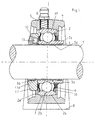
- Fig. 1 of the drawings shows a portion of a cylindrical shaft 1, with a single row deep groove ball bearing 2, mounted thereon via a tapering clamping sleeve 3, and positioned in a bearing housing 4.
- the bearing 2 is of the type known as insert bearing, and it has an outer race ring 2a having a convexly curved outer envelope surface 2b.
- the housing 4 has an concave inner envelope surface 4a of substantially the same radius of curvature as the outer envelope surface of the outer race ring 2a.
- a deep-groove ball bearing which itself can permit neither angular nor axial displacement between the bearing rings, constitutes this insert bearing, and due to the provision of the mating curved surfaces of the outer race ring and the housing the insert bearing unit can permit slight angular misalignment between the housing and the bearing, such as can be caused by long shafts, thermal influence and so on.
- the bearing housing 4 has at least one lubrication hole 5 with a lubricant nipple 6 and an annular lubricant groove 7 in the internal envelope surface.
- the lower side of the housing 4 is designed as a foot portion 8 with which the bearing housing is positioned on a planar surface and attached to this with attachment means, such as bolts (not shown) or the like, whereas the opposite side in the embodiment shown has a convexly curved outer envelope surface.
- the bearing used is a deep groove ball bearing, having an outer ring 2a with a curved outer envelope surface 2b.
- the bearing also comprises an inner race ring 2c, which has a slightly tapering inner envelope surface 2d, and which has a larger axial length than the outer ring.
- Both bearing rings have grooves provided in the confronting envelope surfaces and a number of balls 2e are positioned in these grooves.
- Lip seals 9 are provided at both side axially outside the grooved portions of the bearing rings, and in the example shown a flinger plate 10 is provided outside one of the seals to protect the seal lip.
- the device may have one, two or no such flinger plate.
- the slightly tapering inner envelope surface 2d of the inner ring 2c cooperates with the correspondingly tapering outer envelope surface 3a of the clamping sleeve 3, which has a cylindrical inner envelope surface and which is provided with a longitudinal slot (not shown in the drawing).
- the confronting surfaces 2d and 3a of the inner race ring 2c and the clamping sleeve 3 are both designed with mating saw-tooth longitudinal section profiles for giving the clamping surfaces such a small radial extension as possible, thereby to minimize the overall dimension of the bearing unit.
- the clamping sleeve 3 at one side is provided with an radially outwardly projecting annular flange 11, which is secured to the sleeve 3, thus that it can not move axially relative to the sleeve 3 in at least one direction.
- this is achieved in that the separate flange has an inner annular projection 11a abutting an external annular shoulder 3b provided on the sleeve 3.
- the flange 11 may of course also be designed as an integral portion of the sleeve 3, even if the divided form shown in the drawing is preferred for manufacturing reasons and for not negatively influencing the radial compressibility of the sleeve.
- the flange 11 is provided with at least one threaded through-hole 12 arranged under an acute angle a to the axial direction of the inner envelope surface of the sleeve 3.
- a set screw 13 is positioned in each through-hole 12 and when the said screw(s) is/are screwed into their holes the forward end of each screw will press directly against the side face of the inner race ring 2c, thereby urging the inner race ring 2c to move in mounting direction thereby increasing the clamping effect between itself, the clamping sleeve 3 and the shaft 1. In this manner a safe mounting and retention of the insert bearing unit is obtained in a simple and efficient manner, which can be standardized for most applications of such bearings
- the oblique positioning of the bore-holes 12 gives the advantage that there is better space for the tool used for tightening the set screws. Furthermore the risk for wringing of the clamping sleeve and/or of flange and bearing inner ring is substantially reduced. The driving up force is smaller in comparison to the surface pressure force, which also gives a better possibility to adapt the clamping force. Finally it is also clear that the entire unit consisting of sealed bearing, bearing housing, clamping sleeve and its flange with set screws will be delivered and handled as a self-contained unit, thereby reducing the number of details to handle substantially.
- the embodiment according to Fig. 2 differs from that according to Fig. 1 in that the flange 11 in addition to its inner annular projection 11a also has a second internal annular projection 11b arranged axially outside the first annular projection 11a and adapted to embrace the outer end of the sleeve 3.
- this second projection 11b the dismounting of the joint is simplified, as the sleeve 3 will be carried along in axial direction, when the flange 11 is subjected to an impact axially towards the bearing, when the set screw 13 has been untightened.
- it is an easy task to move the sleeve 3 so in relation to the shaft and the inner race ring of the bearing that the grip between sleeve and bearing ring will cease or at least be substantially reduced.
Landscapes
- Engineering & Computer Science (AREA)
- General Engineering & Computer Science (AREA)
- Mechanical Engineering (AREA)
- Mounting Of Bearings Or Others (AREA)
- Support Of The Bearing (AREA)
- Rolling Contact Bearings (AREA)
Applications Claiming Priority (2)
| Application Number | Priority Date | Filing Date | Title |
|---|---|---|---|
| SE9802262A SE512651C2 (sv) | 1998-06-25 | 1998-06-25 | Lagerenhet |
| SE9802262 | 1998-06-25 |
Publications (3)
| Publication Number | Publication Date |
|---|---|
| EP0967404A2 true EP0967404A2 (de) | 1999-12-29 |
| EP0967404A3 EP0967404A3 (de) | 2000-12-06 |
| EP0967404B1 EP0967404B1 (de) | 2002-10-23 |
Family
ID=20411837
Family Applications (1)
| Application Number | Title | Priority Date | Filing Date |
|---|---|---|---|
| EP99850095A Expired - Lifetime EP0967404B1 (de) | 1998-06-25 | 1999-06-04 | Vorrichtung zur Montage einer Lagereinheit |
Country Status (6)
| Country | Link |
|---|---|
| US (1) | US6152604A (de) |
| EP (1) | EP0967404B1 (de) |
| JP (1) | JP3051840B2 (de) |
| CN (1) | CN1088810C (de) |
| DE (1) | DE69903594T2 (de) |
| SE (1) | SE512651C2 (de) |
Cited By (5)
| Publication number | Priority date | Publication date | Assignee | Title |
|---|---|---|---|---|
| EP1314904A1 (de) * | 2001-11-16 | 2003-05-28 | Aktiebolaget SKF | Verfahren zum Befestigen einer Hülse auf einer Welle und Hülsenvorrichtung für solch eine Befestigung |
| WO2008076011A1 (en) * | 2006-12-20 | 2008-06-26 | Aktiebolaget Skf | A spherical roller bearing with integrated locking device |
| WO2009091297A1 (en) | 2008-01-15 | 2009-07-23 | Aktiebolaget Skf | Simplified rolling bearing unit and a method for manufacturing such a bearing unit |
| CN110397680A (zh) * | 2019-08-26 | 2019-11-01 | 际华三五四二纺织有限公司 | 一种验布机用组合式轴承套 |
| US12577987B2 (en) | 2022-02-21 | 2026-03-17 | Aktiebolaget, SKF | Bearing unit with optimized clamping device |
Families Citing this family (17)
| Publication number | Priority date | Publication date | Assignee | Title |
|---|---|---|---|---|
| US6491497B1 (en) * | 2000-09-22 | 2002-12-10 | General Electric Company | Method and apparatus for supporting rotor assemblies during unbalances |
| US6843762B2 (en) | 2000-12-18 | 2005-01-18 | Spencer Johnston Company | Spreader roll |
| US6482141B1 (en) * | 2001-07-25 | 2002-11-19 | Spencer Johnston Company | Flexible end supporting arrangement for direct drive adjustable spreader rolls |
| US7344313B2 (en) | 2004-05-19 | 2008-03-18 | Qm Holdings Ltd. | Taper lock bearing assembly |
| FI117300B (fi) * | 2005-04-29 | 2006-08-31 | Sulzer Pumpen Ag | Virtauskone, sen liukurengastiiviste, liukurengastiivisteen runkokappale ja menetelmä liukurengastiivisteen kiinnittämiseksi virtauskoneeseen |
| JP4637871B2 (ja) * | 2007-06-11 | 2011-02-23 | 日本ピローブロック株式会社 | 軸受等用の止めネジ |
| DK2195548T3 (da) * | 2007-08-31 | 2013-11-18 | Skf Ab | Leje, og fremgangsmåde og håndtering af lejet |
| US8398310B2 (en) * | 2008-04-21 | 2013-03-19 | Total Lubrication Management Company | Self aligning bearing and seal assembly |
| US8167531B2 (en) * | 2008-05-16 | 2012-05-01 | General Electric Company | Method and apparatus for supporting rotor assemblies during unbalances |
| JP5236082B2 (ja) * | 2008-12-02 | 2013-07-17 | アクティエボラゲット・エスコーエッフ | 一体型センサーを備える回転ベアリング |
| US8961063B2 (en) | 2010-12-02 | 2015-02-24 | Coupling Corporation Of America, Inc. | Hub clamp assembly |
| US10487932B2 (en) * | 2016-11-30 | 2019-11-26 | GM Global Technology Operations LLC | Vehicle differential |
| FR3066534B1 (fr) * | 2017-05-22 | 2020-01-10 | Safran Aircraft Engines | Ensemble pour turbomachine d'aeronef presentant un systeme de decouplage ameliore en cas de perte d'aube de soufflante |
| DE102017130828A1 (de) * | 2017-12-21 | 2019-06-27 | Schaeffler Technologies AG & Co. KG | Gegenplatte für eine Reibungskupplung |
| IT202000001081A1 (it) * | 2020-01-22 | 2021-07-22 | Skf Ab | Elemento di alloggiamento con unità cuscinetto movibile assialmente |
| CN111637167A (zh) * | 2020-07-03 | 2020-09-08 | 河北三头牛机械科技有限公司 | 一种新型刀轴轴承座 |
| CN116892575B (zh) * | 2023-09-11 | 2024-01-09 | 河北佳顺不锈钢轴承制造有限公司 | 一种可调心式轴承座 |
Citations (2)
| Publication number | Priority date | Publication date | Assignee | Title |
|---|---|---|---|---|
| EP0235366A2 (de) | 1986-01-24 | 1987-09-09 | SKF Mekanprodukter AB | Lager mit einer Abdichtung |
| EP0388378A1 (de) | 1989-03-17 | 1990-09-19 | SKF Mekanprodukter AB | Montagevorrichtung für ein Lager auf einer Welle |
Family Cites Families (8)
| Publication number | Priority date | Publication date | Assignee | Title |
|---|---|---|---|---|
| US3623782A (en) * | 1970-03-30 | 1971-11-30 | Toyo Bearing Mfg Co | Device for preventing spin of outer race in bearing unit |
| CA1004867A (en) * | 1973-02-09 | 1977-02-08 | Borg-Warner Corporation | Shaft locking device |
| US4235489A (en) * | 1978-08-15 | 1980-11-25 | Skf Industries, Inc. | External device for selectively converting a pillow block between free and held positions |
| US4596477A (en) * | 1985-01-30 | 1986-06-24 | Skf Nova Ab | Device for fastening a machine element |
| US5011306A (en) * | 1990-03-09 | 1991-04-30 | Reliance Electric Industrial Company | Apparatus for mounting a bearing or other device and tapered adapter onto a shaft |
| CH685019A5 (de) * | 1991-11-21 | 1995-02-28 | Daverio Ag | Lageranordnung mit einem Radiallager. |
| SE502137C2 (sv) * | 1992-04-10 | 1995-08-28 | Skf Mekanprodukter Ab | Anordning för montering och demontering av ett lager på en axel |
| US5373636A (en) * | 1992-10-07 | 1994-12-20 | Reliance Electric Industrial Company | Bearing removal system |
-
1998
- 1998-06-25 SE SE9802262A patent/SE512651C2/sv not_active IP Right Cessation
-
1999
- 1999-06-04 DE DE69903594T patent/DE69903594T2/de not_active Expired - Lifetime
- 1999-06-04 EP EP99850095A patent/EP0967404B1/de not_active Expired - Lifetime
- 1999-06-16 JP JP11169143A patent/JP3051840B2/ja not_active Expired - Lifetime
- 1999-06-25 CN CN99108843A patent/CN1088810C/zh not_active Expired - Lifetime
- 1999-06-25 US US09/339,949 patent/US6152604A/en not_active Expired - Lifetime
Patent Citations (2)
| Publication number | Priority date | Publication date | Assignee | Title |
|---|---|---|---|---|
| EP0235366A2 (de) | 1986-01-24 | 1987-09-09 | SKF Mekanprodukter AB | Lager mit einer Abdichtung |
| EP0388378A1 (de) | 1989-03-17 | 1990-09-19 | SKF Mekanprodukter AB | Montagevorrichtung für ein Lager auf einer Welle |
Cited By (8)
| Publication number | Priority date | Publication date | Assignee | Title |
|---|---|---|---|---|
| EP1314904A1 (de) * | 2001-11-16 | 2003-05-28 | Aktiebolaget SKF | Verfahren zum Befestigen einer Hülse auf einer Welle und Hülsenvorrichtung für solch eine Befestigung |
| US7037026B2 (en) | 2001-11-16 | 2006-05-02 | Ab Skf | Method for mounting a sleeve on a shaft and a sleeve device for such mounting |
| WO2008076011A1 (en) * | 2006-12-20 | 2008-06-26 | Aktiebolaget Skf | A spherical roller bearing with integrated locking device |
| WO2009091297A1 (en) | 2008-01-15 | 2009-07-23 | Aktiebolaget Skf | Simplified rolling bearing unit and a method for manufacturing such a bearing unit |
| US8510954B2 (en) | 2008-01-15 | 2013-08-20 | Aktiebolaget Skf | Simplified rolling bearing unit and a method for manufacturing such a bearing unit |
| EP2242937A4 (de) * | 2008-01-15 | 2016-02-17 | Skf Ab | Vereinfachte kugellagereinheit und verfahren zur herstellung einer solchen kugellagereinheit |
| CN110397680A (zh) * | 2019-08-26 | 2019-11-01 | 际华三五四二纺织有限公司 | 一种验布机用组合式轴承套 |
| US12577987B2 (en) | 2022-02-21 | 2026-03-17 | Aktiebolaget, SKF | Bearing unit with optimized clamping device |
Also Published As
| Publication number | Publication date |
|---|---|
| SE512651C2 (sv) | 2000-04-17 |
| SE9802262D0 (sv) | 1998-06-25 |
| CN1243923A (zh) | 2000-02-09 |
| DE69903594T2 (de) | 2003-07-03 |
| EP0967404A3 (de) | 2000-12-06 |
| US6152604A (en) | 2000-11-28 |
| SE9802262L (sv) | 1999-12-27 |
| CN1088810C (zh) | 2002-08-07 |
| JP3051840B2 (ja) | 2000-06-12 |
| DE69903594D1 (de) | 2002-11-28 |
| EP0967404B1 (de) | 2002-10-23 |
| JP2000035035A (ja) | 2000-02-02 |
Similar Documents
| Publication | Publication Date | Title |
|---|---|---|
| EP0967404B1 (de) | Vorrichtung zur Montage einer Lagereinheit | |
| US8157450B2 (en) | Waveform expansion sleeve for a bearing | |
| EP0485954B1 (de) | Kurbelvorrichtung für Tretlager eines Fahrrads | |
| CA2565903C (en) | Taper lock bearing assembly | |
| US6921211B2 (en) | Bearing housing and seal assembly in such a bearing housing | |
| JP2511112B2 (ja) | 蓋付き旋回輪軸受の潤滑装置 | |
| EP0844409A2 (de) | Lagervorrichtung | |
| US5330284A (en) | Apparatus for mounting and dismounting bearings | |
| US5536090A (en) | Expansion bearing having improved lubrication arrangement | |
| EP2860416B1 (de) | Kugellager | |
| US4673302A (en) | Double row cylindrical expansion bearing | |
| US6682226B2 (en) | Cylindrical roller bearing with preload capability | |
| CA1245699A (en) | Means for securing a bearing to a shaft | |
| US10408259B1 (en) | Self-aligning roller bearing | |
| WO2008076011A1 (en) | A spherical roller bearing with integrated locking device | |
| US11371558B2 (en) | Roller bearing ring and dismounting procedure | |
| FI114166B (fi) | Laakerielin | |
| US11371560B1 (en) | Sealing device for pillow blocks | |
| RU2165811C2 (ru) | Подшипниковая опора прокатного валка | |
| US20260085724A1 (en) | Bearing device | |
| JP2007327565A (ja) | 車輪用軸受装置 | |
| JP2003097565A (ja) | アンギュラ玉軸受 | |
| US20070211975A1 (en) | Inner primary bearing race | |
| JP2005265100A (ja) | 一方向クラッチ内蔵型プーリ装置 |
Legal Events
| Date | Code | Title | Description |
|---|---|---|---|
| PUAI | Public reference made under article 153(3) epc to a published international application that has entered the european phase |
Free format text: ORIGINAL CODE: 0009012 |
|
| AK | Designated contracting states |
Kind code of ref document: A2 Designated state(s): DE FR GB IT |
|
| AX | Request for extension of the european patent |
Free format text: AL;LT;LV;MK;RO;SI |
|
| PUAL | Search report despatched |
Free format text: ORIGINAL CODE: 0009013 |
|
| AK | Designated contracting states |
Kind code of ref document: A3 Designated state(s): AT BE CH CY DE DK ES FI FR GB GR IE IT LI LU MC NL PT SE |
|
| AX | Request for extension of the european patent |
Free format text: AL;LT;LV;MK;RO;SI |
|
| RIC1 | Information provided on ipc code assigned before grant |
Free format text: 7F 16C 35/073 A, 7F 16C 23/08 B, 7F 16C 33/78 B |
|
| 17P | Request for examination filed |
Effective date: 20010606 |
|
| AKX | Designation fees paid |
Free format text: DE FR GB IT |
|
| GRAG | Despatch of communication of intention to grant |
Free format text: ORIGINAL CODE: EPIDOS AGRA |
|
| GRAH | Despatch of communication of intention to grant a patent |
Free format text: ORIGINAL CODE: EPIDOS IGRA |
|
| 17Q | First examination report despatched |
Effective date: 20020424 |
|
| GRAH | Despatch of communication of intention to grant a patent |
Free format text: ORIGINAL CODE: EPIDOS IGRA |
|
| GRAA | (expected) grant |
Free format text: ORIGINAL CODE: 0009210 |
|
| AK | Designated contracting states |
Kind code of ref document: B1 Designated state(s): DE FR GB IT |
|
| REG | Reference to a national code |
Ref country code: GB Ref legal event code: FG4D |
|
| REF | Corresponds to: |
Ref document number: 69903594 Country of ref document: DE Date of ref document: 20021128 |
|
| ET | Fr: translation filed | ||
| PLBE | No opposition filed within time limit |
Free format text: ORIGINAL CODE: 0009261 |
|
| STAA | Information on the status of an ep patent application or granted ep patent |
Free format text: STATUS: NO OPPOSITION FILED WITHIN TIME LIMIT |
|
| 26N | No opposition filed |
Effective date: 20030724 |
|
| REG | Reference to a national code |
Ref country code: DE Ref legal event code: R082 Ref document number: 69903594 Country of ref document: DE Representative=s name: PATENTANWAELTE OLBRICHT, BUCHHOLD, KEULERTZ PA, DE |
|
| REG | Reference to a national code |
Ref country code: FR Ref legal event code: PLFP Year of fee payment: 18 |
|
| REG | Reference to a national code |
Ref country code: FR Ref legal event code: PLFP Year of fee payment: 19 |
|
| REG | Reference to a national code |
Ref country code: FR Ref legal event code: PLFP Year of fee payment: 20 |
|
| PGFP | Annual fee paid to national office [announced via postgrant information from national office to epo] |
Ref country code: FR Payment date: 20180629 Year of fee payment: 20 Ref country code: IT Payment date: 20180620 Year of fee payment: 20 |
|
| PGFP | Annual fee paid to national office [announced via postgrant information from national office to epo] |
Ref country code: GB Payment date: 20180629 Year of fee payment: 20 Ref country code: DE Payment date: 20180831 Year of fee payment: 20 |
|
| REG | Reference to a national code |
Ref country code: DE Ref legal event code: R071 Ref document number: 69903594 Country of ref document: DE |
|
| REG | Reference to a national code |
Ref country code: GB Ref legal event code: PE20 Expiry date: 20190603 |
|
| PG25 | Lapsed in a contracting state [announced via postgrant information from national office to epo] |
Ref country code: GB Free format text: LAPSE BECAUSE OF EXPIRATION OF PROTECTION Effective date: 20190603 |