EP0967366A1 - Kraft-Wärme-Kopplungsanlage und Verfahren zu seinem Betrieb - Google Patents
Kraft-Wärme-Kopplungsanlage und Verfahren zu seinem Betrieb Download PDFInfo
- Publication number
- EP0967366A1 EP0967366A1 EP99202016A EP99202016A EP0967366A1 EP 0967366 A1 EP0967366 A1 EP 0967366A1 EP 99202016 A EP99202016 A EP 99202016A EP 99202016 A EP99202016 A EP 99202016A EP 0967366 A1 EP0967366 A1 EP 0967366A1
- Authority
- EP
- European Patent Office
- Prior art keywords
- internal combustion
- combustion engine
- main line
- blow
- fan
- Prior art date
- Legal status (The legal status is an assumption and is not a legal conclusion. Google has not performed a legal analysis and makes no representation as to the accuracy of the status listed.)
- Granted
Links
- 238000000034 method Methods 0.000 title claims description 8
- 238000002485 combustion reaction Methods 0.000 claims abstract description 139
- 239000007789 gas Substances 0.000 claims abstract description 20
- 238000011144 upstream manufacturing Methods 0.000 claims abstract description 9
- 238000007599 discharging Methods 0.000 claims abstract description 6
- 239000000446 fuel Substances 0.000 claims description 4
- 230000007423 decrease Effects 0.000 claims description 2
- 230000015556 catabolic process Effects 0.000 claims 1
- 239000003546 flue gas Substances 0.000 description 22
- 230000001105 regulatory effect Effects 0.000 description 6
- UGFAIRIUMAVXCW-UHFFFAOYSA-N Carbon monoxide Chemical compound [O+]#[C-] UGFAIRIUMAVXCW-UHFFFAOYSA-N 0.000 description 5
- 238000004519 manufacturing process Methods 0.000 description 2
- 238000007664 blowing Methods 0.000 description 1
- 238000001816 cooling Methods 0.000 description 1
- 230000003247 decreasing effect Effects 0.000 description 1
- 238000002955 isolation Methods 0.000 description 1
- 230000000630 rising effect Effects 0.000 description 1
Images

Classifications
-
- F—MECHANICAL ENGINEERING; LIGHTING; HEATING; WEAPONS; BLASTING
- F01—MACHINES OR ENGINES IN GENERAL; ENGINE PLANTS IN GENERAL; STEAM ENGINES
- F01K—STEAM ENGINE PLANTS; STEAM ACCUMULATORS; ENGINE PLANTS NOT OTHERWISE PROVIDED FOR; ENGINES USING SPECIAL WORKING FLUIDS OR CYCLES
- F01K23/00—Plants characterised by more than one engine delivering power external to the plant, the engines being driven by different fluids
- F01K23/02—Plants characterised by more than one engine delivering power external to the plant, the engines being driven by different fluids the engine cycles being thermally coupled
- F01K23/06—Plants characterised by more than one engine delivering power external to the plant, the engines being driven by different fluids the engine cycles being thermally coupled combustion heat from one cycle heating the fluid in another cycle
- F01K23/10—Plants characterised by more than one engine delivering power external to the plant, the engines being driven by different fluids the engine cycles being thermally coupled combustion heat from one cycle heating the fluid in another cycle with exhaust fluid of one cycle heating the fluid in another cycle
- F01K23/103—Plants characterised by more than one engine delivering power external to the plant, the engines being driven by different fluids the engine cycles being thermally coupled combustion heat from one cycle heating the fluid in another cycle with exhaust fluid of one cycle heating the fluid in another cycle with afterburner in exhaust boiler
-
- Y—GENERAL TAGGING OF NEW TECHNOLOGICAL DEVELOPMENTS; GENERAL TAGGING OF CROSS-SECTIONAL TECHNOLOGIES SPANNING OVER SEVERAL SECTIONS OF THE IPC; TECHNICAL SUBJECTS COVERED BY FORMER USPC CROSS-REFERENCE ART COLLECTIONS [XRACs] AND DIGESTS
- Y02—TECHNOLOGIES OR APPLICATIONS FOR MITIGATION OR ADAPTATION AGAINST CLIMATE CHANGE
- Y02P—CLIMATE CHANGE MITIGATION TECHNOLOGIES IN THE PRODUCTION OR PROCESSING OF GOODS
- Y02P80/00—Climate change mitigation technologies for sector-wide applications
- Y02P80/10—Efficient use of energy, e.g. using compressed air or pressurized fluid as energy carrier
- Y02P80/15—On-site combined power, heat or cool generation or distribution, e.g. combined heat and power [CHP] supply
Definitions
- the invention relates to a combined heat and power plant, comprising: an internal combustion engine; a steam boiler; a main line which connects an outlet of the internal combustion engine to an inlet of the boiler, for discharging gases from the internal combustion engine to the boiler; a main line valve, accommodated in the main line, for opening and closing the latter in a controllable manner; an air supply line which opens out into the main line downstream of the main line valve, and in which a fan for supplying combustion air to the main line is accommodated; an air supply line valve, accommodated in the air supply line downstream of the fan, for opening and closing the air supply line in a controllable manner; and a burner accommodated in the main line downstream of the air supply line.
- the invention also relates to a method for operating such a combined heat and power plant.
- a combined heat and power plant generally comprises an internal combustion turbine connected to an electric generator.
- an internal combustion turbine instead of an internal combustion turbine, another internal combustion engine, such as a piston engine, can also be used. Where an internal combustion turbine is mentioned in this document, this term also includes any other internal combustion engine.
- the flue gases from the internal combustion turbine are discharged directly by way of a main line to a steam boiler, below simply called a boiler.
- the main line per se can comprise several parallel lines. In this arrangement the internal combustion turbine and the boiler can only be in operation simultaneously.
- the main line between the internal combustion turbine and the boiler is provided with a branch line which discharges the flue gases into the atmosphere and which can process the maximum output of flue gases and can be shut off and opened by means of a branch line valve.
- a main line valve is accommodated in the main line, downstream of the branch line, for opening and closing of the main line.
- the branch line valve and the main line valve can be combined to form one change-over valve, which shuts off the main line when the branch line is opened and shuts off the branch line when the main line is opened.
- the plant supplied with a branch line has a burner and a fan added to it.
- the burner is accommodated in the main line between the branch line and the boiler, while the fan can introduce combustion air into the main line at a point between the main line valve and the burner, by way of an air supply line in which a valve is accommodated. If the internal combustion turbine is not available or breaks down, the combination of the burner and the fan supplies the necessary hot flue gases to keep the boiler in operation.
- the circuit described in the previous paragraph makes isolated operation of the internal combustion turbine or isolated operation of the boiler possible, and also parallel operation of the internal combustion turbine and the boiler. Even if isolated operation of the internal combustion turbine is not necessary, when a change-over is made from parallel operation of the internal combustion turbine and the boiler to isolated operation of the boiler, the branch line is necessary for replacing the flue gas stream from the internal combustion turbine to the boiler in a controlled manner by the flue gas stream from the burner. The branch line is also necessary when a change-over is made from isolated operation of the boiler to parallel operation of the internal combustion turbine and the boiler, in the case of which the flue gas stream from the burner to the boiler is replaced in a controlled manner by the flue gas stream from the internal combustion turbine. Moreover, the branch line is necessary for running down and cooling off the internal combustion turbine after it has been separated from the boiler.
- a disadvantage of the use of a branch line is that the valve(s) with its/their seal(s) start(s) to leak, which in the case of parallel operation of the internal combustion turbine and the boiler leads to loss of efficiency which increases exponentially with increasing size of the valves used.
- the object of the invention is to provide a combined heat and power plant which has greatly reduced leakage losses, is considerably cheaper, and the regulation, control and protection of which can be achieved in a considerably simpler way.
- the combined heat and power plant according to the invention is characterized in that upstream of the main line valve the main line is provided with a blow-off line which blows off into the atmosphere, and in which a blow-off line valve is accommodated, for opening and closing the blow-off line in a controllable manner, the blow-off line being adapted to discharge at most the gas output generated by the internal combustion engine at a blow-off rotational speed which is lower than the nominal rotational speed.
- the blow-off rotational speed is substantially equal to the starting rotational speed at which the internal combustion engine is started up. For an internal combustion turbine, this starting rotational speed is lower than about one thousand revolutions per minute, in particular between about five hundred and eight hundred revolutions per minute.
- the branch line with a branch line valve customary in the prior art has been dispensed with, both the above having to be designed for the discharge of the flue gas stream from the internal combustion engine when the latter is under full load. They are replaced according to the invention by simply providing the abovementioned blow-off line and the abovementioned blow-off line valve, both of which need only be designed for the discharge of the gas stream from the internal combustion engine at its (relatively low) blow-off rotational speed, which gas stream consists mainly of air and possibly combustible residual gas components to be vented out, and not of hot flue gases.
- the invention is partly based on the insight that the hot flue gases from the internal combustion engine can be discharged by way of the main line and the steam boiler during all operational processes and in all operational states of the plant.
- the blow-off line valve is fully closed and the main line valve is open.
- the blow-off line valve is already fully closed and the main line valve is already opened before the internal combustion engine is started up.
- the hot flue gases in that case and also in other operating states need not be discharged through the blow-off line.
- the blow-off line between the internal combustion engine and the main line valve is the line descending from the main line with the highest gas throughput capacity, higher than that of any other descending line.
- the blow-off line can be produced cheaply, owing to the relatively low standards which it has to meet.
- the characteristic of the fan is selected in such a way that the output of the fan falls when there is an increase in pressure at the delivery side of the fan.
- Fig. 1 shows a conventional combined heat and power plant with an internal combustion turbine 1, which is connected to an electric generator 2 for generating electric energy. Flue gases coming from the internal combustion turbine 1 are discharged through a main line 3 to a steam boiler 4. A regulable main line valve 5, which can shut off the main line 3 fully or partially to an extent to be predetermined (by means of a regulating mechanism 5a), is accommodated in the main line 3.
- a branch line 6 is fitted between the internal combustion turbine 1 and the main line valve 5, which branch line leads to a stack 7, which discharges the spent gases into the atmosphere (also known as an emergency stack or bypass stack).
- a stack 7 normally has a diameter of several metres, generally three to four metres, and represents a considerable capital investment.
- a regulable branch line valve 8 is accommodated in the branch line 6, which valve can fully or partially shut off the branch line 6 to an extent to be predetermined (by means of a regulating mechanism 8a), in coordination with the position of the main line valve 5.
- the branch line valve 8 is provided with emergency opening means 8b which react to the pressure in the main line 3 between the internal combustion turbine 1 and the main line valve 5 rising above a certain value, by opening the branch line valve 8.
- the emergency opening means 8b has to be capable of discharging the full exhaust capacity of the internal combustion turbine 1 directly to the atmosphere.
- An air supply line 9, which opens out into the main line 3 is installed between the main line valve 5 and the boiler 4, by way of which air supply line combustion air can be forced by means of a fan 10 into the main line 3.
- An auxiliary burner 12 is accommodated in the main line 3 between the air supply line 9 and the boiler 4.
- the auxiliary burner 12 receives fuel by way of a line 13.
- branch line valve 8 For starting up of the internal combustion turbine 1 in isolated operation, the branch line valve 8 is opened and the main line valve 5 is closed, and this state is maintained while the internal combustion turbine 1 is being brought up to the desired load and during normal operation thereafter.
- the branch line valve 8 For starting up of the internal combustion turbine 1 in parallel operation of the internal combustion turbine 1 and the boiler 4, the branch line valve 8 is opened and the main line valve 5 is closed, or vice versa.
- the internal combustion turbine 1 is put into operation up to a minimum electric load of a few per cent. If the internal combustion turbine is started up on the branch line 6, the main line valve 5 is then opened and the branch line valve 8 is closed.
- the boiler 4 can now be put into operation, after which the internal combustion turbine 1 is brought up to the desired load.
- the load of the boiler 4 follows the load of the internal combustion turbine 1.
- the internal combustion turbine 1 When stopping the plant when the internal combustion turbine 1 and the boiler 4 are in parallel operation, the internal combustion turbine 1 is brought down to a minimum load, after which it is put out of operation. The boiler 4 is then put out of operation. In this case also, the load of the boiler 4 follows the load of the internal combustion turbine 1.
- auxiliary burner 12 and the boiler 4 are in operation, and the internal combustion turbine 1 is put into operation in a planned manner to take over the operation of the auxiliary burner 12, the following occurs in a predetermined manner:
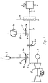
- Fig. 2 shows a combined heat and power plant according to the invention, with the internal combustion turbine 1 connected to the electric generator 2. Flue gases coming from the internal combustion turbine 1 are discharged through the main line 3 to the steam boiler 4.
- the regulable main line valve 5' is accommodated in the main line 3, which valve can fully or partially shut off the main line 3 to an extent to be predetermined (by means of a regulating mechanism 5'a).
- the main line valve 5' is provided with emergency opening means 5'b, which react by opening the main line valve 5' when the pressure in the main line 3 between the internal combustion turbine 1 and the main line valve 5' rises above a certain value. It has been found that the emergency opening means 5'b, which discharge flue gases through the steam boiler 4, ensure safe operation of the combined heat and power plant and permit reliable and efficient operation of the plant (in particular also (isolated) operation of the steam boiler 4).
- the air supply line 9, which opens out into the main line 3, is installed between the main line valve 5' and the boiler 4, by way of which air supply line combustion air can be forced into the main line 3 by means of the fan 10.
- the regulable air supply line valve 11 is accommodated in the air supply line 9, which valve can fully or partially shut off the air supply line 9 to an extent to be predetermined (by means of a regulating mechanism 11a), in coordination with the opening position of the main line valve 5'.
- the auxiliary burner 12 is accommodated in the main line 3 between the air supply line 9 and the boiler 4.
- the auxiliary burner 12 receives fuel by way of the line 13.
- the main line 3 is provided with a blow-off line 14, in which a regulable blow-off line valve 15 is accommodated, which valve can fully or partially shut off the blow-off line to an extent to be predetermined (by means of a regulating mechanism 15a).
- a branch line and a branch line valve are absent and have been replaced by a blow-off line 14 with a blow-off line valve 15.
- the blow-off line 14 has a considerably lower capacity than the branch line 6 according to Fig. 1, and the blow-off line valve 15 is considerably smaller and simpler than the branch line valve 8 according to Fig. 1.
- the capacity of the blow-off line 14 is approx. 15 to 20 per cent of the capacity of the main line 3. This capacity is sufficient for blowing off the gas output, which is blown off at higher blow-off rotational speeds (up to approx. 1000 revolutions per minute) by the internal combustion turbine by way of the main line 3.
- the blow-off line 14 need not be suitable for discharging flue gases from the internal combustion turbine 1, since these flue gases can be discharged by way of the main line 3 through the steam boiler 4.
- the main line valve 5' is opened.
- the internal combustion turbine 1 is first put into operation up to a minimum electric load of a few per cent.
- the boiler 4 is then put into operation, after which the internal combustion turbine 1 is brought up to the desired load.
- the load of the boiler 4 follows the load of the internal combustion turbine 1.
- the internal combustion turbine 1 For stopping the plant in parallel operation of the internal combustion turbine 1 and the boiler 4, the internal combustion turbine 1 is brought down to a minimum load, after which the internal combustion turbine is put out of operation. The boiler 4 is subsequently put out of operation. In this case also, the load of the boiler 4 follows the load of the internal combustion turbine 1.
- the internal combustion turbine 1 now runs down further by way of the blow-off line 14.
Landscapes
- Engineering & Computer Science (AREA)
- Chemical & Material Sciences (AREA)
- Combustion & Propulsion (AREA)
- Mechanical Engineering (AREA)
- General Engineering & Computer Science (AREA)
- Engine Equipment That Uses Special Cycles (AREA)
- Control Of Steam Boilers And Waste-Gas Boilers (AREA)
Applications Claiming Priority (2)
| Application Number | Priority Date | Filing Date | Title |
|---|---|---|---|
| NL1009467 | 1998-06-22 | ||
| NL1009467A NL1009467C2 (nl) | 1998-06-22 | 1998-06-22 | Warmte-krachtinstallatie, en werkwijze voor het bedrijven daarvan. |
Publications (2)
| Publication Number | Publication Date |
|---|---|
| EP0967366A1 true EP0967366A1 (de) | 1999-12-29 |
| EP0967366B1 EP0967366B1 (de) | 2003-10-15 |
Family
ID=19767362
Family Applications (1)
| Application Number | Title | Priority Date | Filing Date |
|---|---|---|---|
| EP99202016A Expired - Lifetime EP0967366B1 (de) | 1998-06-22 | 1999-06-21 | Kraft-Wärme-Kopplungsanlage und Verfahren zu seinem Betrieb |
Country Status (3)
| Country | Link |
|---|---|
| EP (1) | EP0967366B1 (de) |
| DE (1) | DE69912029T2 (de) |
| NL (1) | NL1009467C2 (de) |
Cited By (7)
| Publication number | Priority date | Publication date | Assignee | Title |
|---|---|---|---|---|
| EP1209412A1 (de) * | 2000-11-24 | 2002-05-29 | Entreprise Generale De Chauffage Industriel Pillard | Nachverbrennungsvorrichtung, die als Oxydationsmittel Gasturbinenrauchgas oder frische Luft verwendet |
| WO2002068801A1 (de) * | 2001-02-27 | 2002-09-06 | Alstom (Switzerland) Ltd | Verfahren zur nachrüstung eines dampfsystems |
| WO2002077420A1 (de) * | 2001-03-27 | 2002-10-03 | Alstom (Switzerland) Ltd | Verfahren zur sofortigen, schnellen und temporären erhöhung der leistung eines kombikraftwerkes |
| EP1462632A2 (de) | 2003-03-28 | 2004-09-29 | Alstom Technology Ltd | Verfahren und Vorrichtung zur Anpassung der Parameter des Heissgases eines Heissgaserzeugers mit nachgeschaltetem technologischem Prozess |
| WO2004092643A1 (en) * | 2003-04-08 | 2004-10-28 | Exxonmobil Upstream Research Company | Gas seal apparatus and method for use in cogeneration applications |
| WO2006129150A3 (en) * | 2005-06-01 | 2008-01-17 | Air Liquide | Practical method for improving the efficiency of cogeneration system |
| EP2808501A1 (de) * | 2013-05-27 | 2014-12-03 | Siemens Aktiengesellschaft | Verfahren zum Betreiben einer GuD-Kraftwerksanlage |
Citations (3)
| Publication number | Priority date | Publication date | Assignee | Title |
|---|---|---|---|---|
| DE2609522B1 (de) * | 1976-03-08 | 1977-04-14 | Kraftwerk Union Ag | Schutzeinrichtung für den abgaskanal einer gasturbine in einer kombinierten gasturbinen-dampfkraftanlage |
| DE4319732A1 (de) * | 1993-06-15 | 1994-12-22 | Siemens Ag | Gasturbinenanlage mit nachgeschaltetem Abhitzedampferzeuger |
| DE4434526C1 (de) * | 1994-09-27 | 1996-04-04 | Siemens Ag | Verfahren zum Betreiben einer Gas- und Dampfturbinenanlage sowie danach arbeitende Anlage |
-
1998
- 1998-06-22 NL NL1009467A patent/NL1009467C2/nl not_active IP Right Cessation
-
1999
- 1999-06-21 DE DE69912029T patent/DE69912029T2/de not_active Expired - Lifetime
- 1999-06-21 EP EP99202016A patent/EP0967366B1/de not_active Expired - Lifetime
Patent Citations (3)
| Publication number | Priority date | Publication date | Assignee | Title |
|---|---|---|---|---|
| DE2609522B1 (de) * | 1976-03-08 | 1977-04-14 | Kraftwerk Union Ag | Schutzeinrichtung für den abgaskanal einer gasturbine in einer kombinierten gasturbinen-dampfkraftanlage |
| DE4319732A1 (de) * | 1993-06-15 | 1994-12-22 | Siemens Ag | Gasturbinenanlage mit nachgeschaltetem Abhitzedampferzeuger |
| DE4434526C1 (de) * | 1994-09-27 | 1996-04-04 | Siemens Ag | Verfahren zum Betreiben einer Gas- und Dampfturbinenanlage sowie danach arbeitende Anlage |
Cited By (14)
| Publication number | Priority date | Publication date | Assignee | Title |
|---|---|---|---|---|
| EP1209412A1 (de) * | 2000-11-24 | 2002-05-29 | Entreprise Generale De Chauffage Industriel Pillard | Nachverbrennungsvorrichtung, die als Oxydationsmittel Gasturbinenrauchgas oder frische Luft verwendet |
| FR2817326A1 (fr) * | 2000-11-24 | 2002-05-31 | Pillard Chauffage | Dispositif de postcombustion utilisant, comme comburant, des gaz turbine ou de l'air frais |
| WO2002068801A1 (de) * | 2001-02-27 | 2002-09-06 | Alstom (Switzerland) Ltd | Verfahren zur nachrüstung eines dampfsystems |
| US6810675B2 (en) | 2001-03-27 | 2004-11-02 | Alstom Technology Ltd | Method for operating a combined-cycle power station |
| WO2002077420A1 (de) * | 2001-03-27 | 2002-10-03 | Alstom (Switzerland) Ltd | Verfahren zur sofortigen, schnellen und temporären erhöhung der leistung eines kombikraftwerkes |
| EP1462632A2 (de) | 2003-03-28 | 2004-09-29 | Alstom Technology Ltd | Verfahren und Vorrichtung zur Anpassung der Parameter des Heissgases eines Heissgaserzeugers mit nachgeschaltetem technologischem Prozess |
| US7260938B2 (en) | 2003-03-28 | 2007-08-28 | Alstom Technology, Ltd. | Method and arrangement for adapting a parameter of a hot gas of a hot-gas generator having a downstream technological process |
| EP1462632B1 (de) | 2003-03-28 | 2015-06-17 | Alstom Technology Ltd | Verfahren und Vorrichtung zur Anpassung der Parameter des Heissgases eines Heissgaserzeugers mit nachgeschaltetem technologischem Prozess |
| WO2004092643A1 (en) * | 2003-04-08 | 2004-10-28 | Exxonmobil Upstream Research Company | Gas seal apparatus and method for use in cogeneration applications |
| US7059134B2 (en) | 2003-04-08 | 2006-06-13 | Exxonmobil Upstream Research Company | Gas seal apparatus and method for use in cogeneration applications |
| EA008416B1 (ru) * | 2003-04-08 | 2007-04-27 | Эксонмобил Апстрим Рисерч Компани | Устройство с газовым уплотнением и способ производства тепловой и электрической энергии |
| WO2006129150A3 (en) * | 2005-06-01 | 2008-01-17 | Air Liquide | Practical method for improving the efficiency of cogeneration system |
| EP2808501A1 (de) * | 2013-05-27 | 2014-12-03 | Siemens Aktiengesellschaft | Verfahren zum Betreiben einer GuD-Kraftwerksanlage |
| WO2014191268A3 (de) * | 2013-05-27 | 2015-05-07 | Siemens Aktiengesellschaft | Verfahren zum betreiben einer gud-kraftwerksanlage |
Also Published As
| Publication number | Publication date |
|---|---|
| DE69912029D1 (de) | 2003-11-20 |
| EP0967366B1 (de) | 2003-10-15 |
| DE69912029T2 (de) | 2004-08-12 |
| NL1009467C2 (nl) | 1999-12-27 |
Similar Documents
| Publication | Publication Date | Title |
|---|---|---|
| CN101078368B (zh) | 由使用空气抽取在欠频率运行期间运行燃气涡轮机的方法 | |
| US5309707A (en) | Control methods and valve arrangement for start-up and shutdown of pressurized combustion and gasification systems integrated with a gas turbine | |
| EP2119892A2 (de) | Verfahren zur Regelung eines Sollwertes zur Entnahme von Luft aus einem Verdichter zur Bereitstellung von Turbinenkühlluft in einer Gasturbine | |
| KR20010076202A (ko) | 가스 터빈용 냉각 공기 유동 조절 시스템, 다단 압축기의단에서 관련 터빈으로 공기를 분출하기 위한 시스템, 및다단 압축기에서 관련 터빈으로 냉각 및/또는 퍼지 공기의제공 방법 | |
| US20150107257A1 (en) | Flushing the exhaust gas recirculation lines of a gas turbine | |
| CN104033410A (zh) | 一种大型火力发电机组引风机和增压风机联合控制方法 | |
| JP2000161014A (ja) | コンバインド発電設備 | |
| US11473445B2 (en) | Steam turbine plant and cooling method for same | |
| US6792760B2 (en) | Method for operating a turbine | |
| JP3677536B2 (ja) | ガスタービン発電制御装置 | |
| EP0967366B1 (de) | Kraft-Wärme-Kopplungsanlage und Verfahren zu seinem Betrieb | |
| US4362013A (en) | Method for operating a combined plant | |
| EP2840238B1 (de) | Betrieb eines Gasturbinenkraftwerks mit Kohlenstoffdioxidabscheidung | |
| JPH03932A (ja) | ターボ機械の制御方法およびその制御装置 | |
| JP3530344B2 (ja) | 加圧流動層複合発電システムの圧縮機サージング防止装置 | |
| JP2018165583A (ja) | 焼却炉に付設された過給機のサージ回避方法及びその装置 | |
| EP3425176B1 (de) | Abwärmerückgewinnungsvorrichtung, verbrennungssystem, schiff und steuerungsverfahren für eine abwärmerückgewinnungsvorrichtung | |
| EP1273768B1 (de) | Verfahren zum Betrieb eines Kombikraftwerks | |
| JPH08158890A (ja) | 石炭ガス化複合発電プラントの運転方法 | |
| JP3585544B2 (ja) | 石炭ガス化複合発電プラントの運転方法 | |
| JP3769827B2 (ja) | 湿り空気ガスタービン設備のインタークーラ切替制御装置 | |
| JP2000074308A (ja) | ボイラプラントにおける再熱器のスケール剥離防止方法及び装置 | |
| JP2002129906A (ja) | 蒸気タービン排気室の冷却蒸気供給方法およびその装置 | |
| JPH04342805A (ja) | 排気再燃コンバインドサイクルプラントの排ガス圧力制御方法 | |
| JPS622129B2 (de) |
Legal Events
| Date | Code | Title | Description |
|---|---|---|---|
| PUAI | Public reference made under article 153(3) epc to a published international application that has entered the european phase |
Free format text: ORIGINAL CODE: 0009012 |
|
| AK | Designated contracting states |
Kind code of ref document: A1 Designated state(s): DE FR GB NL |
|
| AX | Request for extension of the european patent |
Free format text: AL;LT;LV;MK;RO;SI |
|
| 17P | Request for examination filed |
Effective date: 20000419 |
|
| AKX | Designation fees paid |
Free format text: DE FR GB NL |
|
| RAP1 | Party data changed (applicant data changed or rights of an application transferred) |
Owner name: NEM B.V. |
|
| 17Q | First examination report despatched |
Effective date: 20021211 |
|
| GRAH | Despatch of communication of intention to grant a patent |
Free format text: ORIGINAL CODE: EPIDOS IGRA |
|
| GRAS | Grant fee paid |
Free format text: ORIGINAL CODE: EPIDOSNIGR3 |
|
| GRAA | (expected) grant |
Free format text: ORIGINAL CODE: 0009210 |
|
| AK | Designated contracting states |
Kind code of ref document: B1 Designated state(s): DE FR GB NL |
|
| PG25 | Lapsed in a contracting state [announced via postgrant information from national office to epo] |
Ref country code: FR Free format text: LAPSE BECAUSE OF FAILURE TO SUBMIT A TRANSLATION OF THE DESCRIPTION OR TO PAY THE FEE WITHIN THE PRESCRIBED TIME-LIMIT Effective date: 20031015 |
|
| REG | Reference to a national code |
Ref country code: GB Ref legal event code: FG4D |
|
| REF | Corresponds to: |
Ref document number: 69912029 Country of ref document: DE Date of ref document: 20031120 Kind code of ref document: P |
|
| PLBE | No opposition filed within time limit |
Free format text: ORIGINAL CODE: 0009261 |
|
| STAA | Information on the status of an ep patent application or granted ep patent |
Free format text: STATUS: NO OPPOSITION FILED WITHIN TIME LIMIT |
|
| 26N | No opposition filed |
Effective date: 20040716 |
|
| EN | Fr: translation not filed | ||
| REG | Reference to a national code |
Ref country code: NL Ref legal event code: SD Effective date: 20111209 |
|
| REG | Reference to a national code |
Ref country code: GB Ref legal event code: 732E Free format text: REGISTERED BETWEEN 20120126 AND 20120201 |
|
| REG | Reference to a national code |
Ref country code: DE Ref legal event code: R082 Ref document number: 69912029 Country of ref document: DE Representative=s name: MAIER, DANIEL OLIVER, DIPL.-ING. UNIV., DE Effective date: 20120301 Ref country code: DE Ref legal event code: R081 Ref document number: 69912029 Country of ref document: DE Owner name: NEM ENERGY B.V., NL Free format text: FORMER OWNER: NEM B.V., LEIDEN, NL Effective date: 20120301 |
|
| REG | Reference to a national code |
Ref country code: DE Ref legal event code: R082 Ref document number: 69912029 Country of ref document: DE Representative=s name: MAIER, DANIEL OLIVER, DIPL.-ING. UNIV., DE |
|
| PGFP | Annual fee paid to national office [announced via postgrant information from national office to epo] |
Ref country code: GB Payment date: 20160610 Year of fee payment: 18 |
|
| PGFP | Annual fee paid to national office [announced via postgrant information from national office to epo] |
Ref country code: NL Payment date: 20160602 Year of fee payment: 18 |
|
| PGFP | Annual fee paid to national office [announced via postgrant information from national office to epo] |
Ref country code: DE Payment date: 20160819 Year of fee payment: 18 |
|
| REG | Reference to a national code |
Ref country code: DE Ref legal event code: R119 Ref document number: 69912029 Country of ref document: DE |
|
| REG | Reference to a national code |
Ref country code: NL Ref legal event code: MM Effective date: 20170701 |
|
| GBPC | Gb: european patent ceased through non-payment of renewal fee |
Effective date: 20170621 |
|
| PG25 | Lapsed in a contracting state [announced via postgrant information from national office to epo] |
Ref country code: NL Free format text: LAPSE BECAUSE OF NON-PAYMENT OF DUE FEES Effective date: 20170701 |
|
| PG25 | Lapsed in a contracting state [announced via postgrant information from national office to epo] |
Ref country code: GB Free format text: LAPSE BECAUSE OF NON-PAYMENT OF DUE FEES Effective date: 20170621 Ref country code: DE Free format text: LAPSE BECAUSE OF NON-PAYMENT OF DUE FEES Effective date: 20180103 |