EP0966387B1 - Verfahren zur ir-tarnung sowie ir-reflektor - Google Patents
Verfahren zur ir-tarnung sowie ir-reflektor Download PDFInfo
- Publication number
- EP0966387B1 EP0966387B1 EP98921337A EP98921337A EP0966387B1 EP 0966387 B1 EP0966387 B1 EP 0966387B1 EP 98921337 A EP98921337 A EP 98921337A EP 98921337 A EP98921337 A EP 98921337A EP 0966387 B1 EP0966387 B1 EP 0966387B1
- Authority
- EP
- European Patent Office
- Prior art keywords
- grooves
- element according
- radiation
- camouflage element
- transparent
- Prior art date
- Legal status (The legal status is an assumption and is not a legal conclusion. Google has not performed a legal analysis and makes no representation as to the accuracy of the status listed.)
- Expired - Lifetime
Links
- 238000000034 method Methods 0.000 title description 3
- 230000005855 radiation Effects 0.000 claims description 22
- 239000004698 Polyethylene Substances 0.000 claims description 7
- 239000000463 material Substances 0.000 claims description 7
- 229920000573 polyethylene Polymers 0.000 claims description 7
- -1 polyethylene Polymers 0.000 claims description 6
- 239000000049 pigment Substances 0.000 claims description 4
- 239000012780 transparent material Substances 0.000 claims description 3
- 239000000853 adhesive Substances 0.000 claims description 2
- 230000001070 adhesive effect Effects 0.000 claims description 2
- 239000004033 plastic Substances 0.000 claims description 2
- 229920003023 plastic Polymers 0.000 claims description 2
- 230000000694 effects Effects 0.000 description 8
- 230000003287 optical effect Effects 0.000 description 4
- 229920000098 polyolefin Polymers 0.000 description 4
- 238000004088 simulation Methods 0.000 description 4
- XLYOFNOQVPJJNP-UHFFFAOYSA-N water Substances O XLYOFNOQVPJJNP-UHFFFAOYSA-N 0.000 description 3
- 238000010521 absorption reaction Methods 0.000 description 2
- 239000002131 composite material Substances 0.000 description 2
- 230000007123 defense Effects 0.000 description 2
- 238000009413 insulation Methods 0.000 description 2
- 238000004519 manufacturing process Methods 0.000 description 2
- 238000001465 metallisation Methods 0.000 description 2
- 230000009467 reduction Effects 0.000 description 2
- 238000012935 Averaging Methods 0.000 description 1
- 241000282326 Felis catus Species 0.000 description 1
- 238000009825 accumulation Methods 0.000 description 1
- 230000006978 adaptation Effects 0.000 description 1
- 238000004026 adhesive bonding Methods 0.000 description 1
- 239000002313 adhesive film Substances 0.000 description 1
- 238000004364 calculation method Methods 0.000 description 1
- 238000011161 development Methods 0.000 description 1
- 230000018109 developmental process Effects 0.000 description 1
- 230000020169 heat generation Effects 0.000 description 1
- 239000012943 hotmelt Substances 0.000 description 1
- 238000003475 lamination Methods 0.000 description 1
- 229920001684 low density polyethylene Polymers 0.000 description 1
- 239000004702 low-density polyethylene Substances 0.000 description 1
- 239000002184 metal Substances 0.000 description 1
- 239000003973 paint Substances 0.000 description 1
- 230000001376 precipitating effect Effects 0.000 description 1
- 230000008569 process Effects 0.000 description 1
- 238000010845 search algorithm Methods 0.000 description 1
- 210000002023 somite Anatomy 0.000 description 1
- 239000000126 substance Substances 0.000 description 1
- 230000001629 suppression Effects 0.000 description 1
- 230000007704 transition Effects 0.000 description 1
Images

Classifications
-
- B—PERFORMING OPERATIONS; TRANSPORTING
- B63—SHIPS OR OTHER WATERBORNE VESSELS; RELATED EQUIPMENT
- B63G—OFFENSIVE OR DEFENSIVE ARRANGEMENTS ON VESSELS; MINE-LAYING; MINE-SWEEPING; SUBMARINES; AIRCRAFT CARRIERS
- B63G13/00—Other offensive or defensive arrangements on vessels; Vessels characterised thereby
- B63G13/02—Camouflage
-
- F—MECHANICAL ENGINEERING; LIGHTING; HEATING; WEAPONS; BLASTING
- F41—WEAPONS
- F41H—ARMOUR; ARMOURED TURRETS; ARMOURED OR ARMED VEHICLES; MEANS OF ATTACK OR DEFENCE, e.g. CAMOUFLAGE, IN GENERAL
- F41H3/00—Camouflage, i.e. means or methods for concealment or disguise
Definitions
- the invention relates to a multispectral camouflage element, in particular for the camouflage of Ships, according to the preamble of claim 1.
- the surface temperature T can be reduced by constructive measures and thus the signature can be reduced. For example, by covering of the chimney or through good thermal insulation of the machine room a considerable camouflage effect can be achieved.
- This constructive Basic measures are very important, and yet this method is general set narrow limits. Extensive insulation of the hull Apart from the costs, it is forbidden because the surface temperature even stronger due to solar radiation, wind, icing, etc. would be influenced and thus rather a negative influence on the Overall signature would result.
- GB 2 274 154 A relates to a device by means of which pivotable mirrors an attempt is made to, in particular, the infrared signatures of the object to be protected of a ship to adapt to its background. This is done using IR sensors the IR signature of the object background as seen from the perspective of an approaching missile, measured. In addition, the current one IR radiation of the object to be protected in the direction of the approaching Missile measured. By reflecting in ambient radiation the IR signature of the object to be protected should be by means of the pivoting mirror be changed so that there is an optimal adaptation to the object background results.
- DE 400 528 describes a camouflage device for ships for the optical wavelength range described, in which a reflector layer is present, the Surface has rectangular V-shaped grooves.
- the grooves become essentially horizontally on the object to be camouflaged, so the observer an image of the horizon is mirrored as everyone is on the reflector layer striking horizontal light beam is thrown back horizontally.
- the basic idea of the invention is the one behind the ship Horizon range by another, in the foreground or lying to the side To replace the horizon area. This is achieved through mirroring the horizon using an IR reflector on board the ship to be protected. On open sea, the apparent temperatures of the horizon are practically independent from the viewing direction as it is essentially determined by the air temperature and scatter effects are determined. Thus, a perfect adjustment of the ship can be reached at its background.
- camouflage element according to the invention not only for Is suitable for ships, but generally for object camouflage, i.e. also on the Country that can be applied.
- the only requirement is that the threat, e.g. by missiles or IR vision devices, mainly from the horizontal he follows.
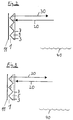
- FIG. 2 shows the structure of a camouflage element according to the invention in the form of a low-emitting microstructure with which the reflection of the horizon according to the invention can advantageously be achieved.
- It comprises a reflector layer 3 made of an IR-reflecting material, in particular a metal such as Al, which is arranged on a base layer 1, for example a structural film made of plastic.
- the reflector layer 3 is to be arranged in front of the base layer 1, viewed from the direction of the incident IR radiation to be reflected.
- the base layer 1 can be arranged directly on the surface of the object to be camouflaged.
- the reflector layer 3 has a groove structure on the side which is to be aligned in the direction of the incident IR radiation to be reflected.
- the grooves run parallel to one another, adjacent grooves advantageously adjoining one another directly, so that overall a washboard-like structure results.
- the cross-section of the grooves is V-shaped, the angle between the two legs being just 90 °.
- the depth of the grooves is selected in the range from approximately 20 ⁇ m to 100 ⁇ m.
- the entire IR reflector structure shown in Fig. 2 can directly on the Object surface 11, e.g. on a ship and its various structures, angry, e.g. be glued.
- the reflector must be aligned so that the Grooves are essentially horizontal.
- the described IR reflector structure can be used as a two-dimensional retro reflector are called, in contrast to the known three-dimensional Retro reflectors, such as those found on vehicle reflectors (cat's eyes) be used. If the grooves are essentially horizontal, remains the angle between an incident beam 20 and the horizontal obtained in the reflection on the reflector layer 3. So in particular a horizontally incident beam always reflects in the horizontal direction. However, there is no retro effect with regard to the azimuth angle, here follows the Beam path the normal specular reflection law.
- every surface element of the ship takes on an apparent temperature that corresponds to that of a lateral horizon area. What area seen in detail depends on the angle between the surface normals and the trajectory. Because the ship structure has many different azimuthal angles includes, in any case, averaging over a larger horizontal area occur.
- the grooves can expediently with an IR-transparent material 9, e.g. Polyethylene (PE) or other polyolefins, are filled to the accumulation to avoid dirt in the grooves.
- PE Polyethylene
- an IR transparent Material e.g. polyethylene or other polyolefins
- the base material for the color film 7 is preferably made of polyolefin, in particular a linear cross-linked low density polyethylene (LLDPE).
- Polyolefins have high IR transparency and thus low absorption of IR radiation on. In order to distort the optical contour of the object to be camouflaged, this can be done
- Base material can be colored with different color pigments.
- the whole can System implemented in the form of a manageable, light composite film become.
- the production of such a camouflage film can be done without major manufacturing effort to reach.
- the groove profile on the Base layer are generated by hot stamping.
- the reflector layer applied by metallization of the carrier film and with the color film, if necessary after inserting the filling for the grooves, laminated.
- FIG. 3 shows a further embodiment of the camouflage element according to the invention.
- an additional, IR-transparent structural film 5 in particular made of polyethylene, one surface of which is formed in such a way that the grooves are filled.
- the groove structure is first produced in the IR-transparent structural film 5 is generated.
- the metallization takes place for applying the reflector layer 3 and lamination with the color film 7.
- the composite is then applied using an adhesive process, e.g. Hot melt gluing, glued to the object to be camouflaged.
- the adhesive film thus forms the base layer 1.
Landscapes
- Engineering & Computer Science (AREA)
- Aviation & Aerospace Engineering (AREA)
- General Engineering & Computer Science (AREA)
- Aiming, Guidance, Guns With A Light Source, Armor, Camouflage, And Targets (AREA)
- Laminated Bodies (AREA)
- Burglar Alarm Systems (AREA)
- Catching Or Destruction (AREA)
Description
- ε:
- Wärme-Emissionsgrad
- σ:
- Stefan-Boltzmann-Konstante
- T:
- Oberflächentemperatur
- Bei klarem Himmel und nach oben geneigten niedrigemissiven Flächen entstehen starke cold spots (bezogen auf die horizontale Beobachtungsrichtung). Seezielflugkörper der nächsten Generation werden in der Lage sein, den Horizont sehr sensibel und mit hoher Auflösung abzutasten. Somit wird ab einer bestimmten Entfernung bei Anwesenheit von starken cold spots ein signifikantes Zielprofil im Suchkopf erzeugt, das dem Flugkörper eine besonders hohe, kaum mehr störbare Treffsicherheit vermittelt.
- Bei sonnigem Wetter kann im SWIR (SWIR= short wave infrared, 3 - 5 µm) ein zusätzlicher Störeffekt in Form von Sonnenreflexen auftreten, welcher durch den Einsatz niedrigemissiver Flächen verstärkt wird. Ein Flugkörper heutiger oder künftiger Bauart wird auch diese hot spots als echtes Ziel identifizieren können.
Die Bedrohung durch Seezielflugkörper erfolgt stets aus der Horizontalen. Das typische Wärmebild einer Szene auf offener See aus der Perspektive eines Seezielflugkörpers ist gekennzeichnet durch
- sehr niedrige Strahlungstemperaturen am Zenith und einem Übergang zu höheren Temperaturen in Richtung Horizont,
- das Schiff weist aufgrund seiner internen Wärmeentwicklung oder durch Sonneneinstrahlung gegenüber dem Wasser in der Regel eine etwas höhere Temperatur auf,
- das Schiff unterbricht die Horizontlinie.
Die Reflektorschicht 3 weist auf der Seite, die in Richtung auf die einfallende, zu reflektierende IR-Strahlung auszurichten ist, eine Rillenstruktur auf. Die Rillen verlaufen parallel zueinander, wobei benachbarte Rillen vorteilhaft unmittelbar aneinander angrenzen, so daß sich insgesamt eine waschbrettartige Struktur ergibt. Der Querschnitt der Rillen ist V-förmig, wobei der Winkel zwischen den beiden Schenkeln gerade 90° beträgt. Für die Tiefe der Rillen (gemessen entlang der Winkelhalbierenden) gilt, daß sie größer als die Wellenlängen der zu reflektierenden IR-Wellenlängen, also mindestens 12 µm, und kleiner als die Wellenlänge von Radarstrahlen, d.h. kleiner als 1 mm, sein muß, damit das Radarrückstreusignal nicht beeinflußt wird. In einer bevorzugten Ausführung wird die Tiefe der Rillen im Bereich von etwa 20 µm bis 100 µm gewählt.
- weitgehende Unterdrückung der eigenen Temperaturstrahlung im gesamten IR-Bereich (SW und LW= long wave infrared, 8 - 12 µm).
- keine Gefahr von cold spot- oder hot spot-Reflexionen.
- völlige Unabhängigkeit von den Schiffsbewegungen
- perfekte Simulation der Hintergrundtemperatur
- keine Unterbrechung der Horizontlinie am Ort des Schiffes
- Simulation des Wellenganges
- keine Beeinflussung des Radarrückstreusignals, da die Abmessungen der IR-Reflektorstruktur wesentlich kleiner gewählt werden können als die Wellenlänge von Radarstrahlen.
- beliebige Farbgebung des Schiffes.
- 1
- Basisschicht
- 3
- Reflektorschicht
- 5
- IR-transparente Strukturfolie
- 7
- Farbfolie fehgrau
- 9
- IR-transparente Füllung
- 11
- Objektoberfläche
- 20
- einfallende IR-Strahlung
- 30
- ausfallender IR-Strahlung
- 40
- Meeresoberfläche
Claims (8)
- Multispektrales Tarnelement, insbesondere für Schiffe, gegen die Aufklärung im sichtoptischen, infraroten und Radarwellenlängenbereich, gekennzeichnet durcheine Basisschicht (1),eine auf der Basisschicht (1) angeordnete Reflektorschicht (3) aus einem IR-reflektierenden Material, deren Oberfläche rechtwinklige, V-förmige Rillen aufweist, wobei die Rillen im wesentlichen horizontal anzuordnen sind, und die Reflektorschicht (3), aus Richtung der einfallenden Strahlung betrachtet, vor der Basisschicht (1) anzuordnen ist,wobei die Tiefe der V-förmigen Rillen der Reflektorschicht (3) größer als die Wellenlänge von IR-Strahlung und kleiner als die Wellenlänge von Radarstrahlung ist, unddas Element in Richtung auf die einfallende Strahlung von einer IR-transparenten Farbfolie (7) mit ebenen Oberflächen abgeschlossen wird.
- Multispektrales Tarnelement nach Anspruch 1, dadurchgekennzeichnet, daß die Tiefe der Rillen im Bereich zwischen 12 µm und 1 mm, bevorzugt zwischen 20 µm bis 100 µm liegt.
- Multispektrales Tarnelement nach einem der Ansprüche 1 oder 2, dadurch gekennzeichnet, daß die Basisschicht (1) aus einem Kunststoffmaterial besteht.
- Multispektrales Tarnelement nach einem der Ansprüche 1 bis 3, da durch gekennzeichnet, daß die Basisschicht (1) aus einem Klebermaterial besteht.
- Multispektrales Tarnelement nach einem der Ansprüche 1 bis 4, dadurch gekennzeichnet, daß die Rillen mit einem IR-transparenten Material (9), z.B. Polyethylen, ausgefüllt sind.
- Multispektrales Tarnelement nach einem der Ansprüche 1 bis 4, dadurch gekennzeichnet, daß die IR-transparente Farbfolie (7) auf der Reflektorschicht (3) derart angeordnet ist, daß die Rillen als Hohlräume erhalten bleiben.
- Multispektrales Tarnelement nach einem der Ansprüche 1 bis 4, dadurch gekennzeichnet, daß zwischen Reflektorschicht (3) und der IR-transparenten Farbfolie (7) eine IR-transparente Schicht (5), z.B. aus Polyethylen angeordnet ist, welche die Rillen ausfüllt.
- Multispektrales Tarnelement nach einem der Ansprüche 1 bis 7 , dadurch gekennzeichnet, daß das Grundmaterial der Farbfolie (7) aus Polyethylen besteht, in welches IR-transparente Farbpigmente eingebracht sind.
Applications Claiming Priority (3)
| Application Number | Priority Date | Filing Date | Title |
|---|---|---|---|
| DE19710692 | 1997-03-14 | ||
| DE19710692A DE19710692C2 (de) | 1997-03-14 | 1997-03-14 | Multispektrales Tarnelement |
| PCT/DE1998/000695 WO1998041445A1 (de) | 1997-03-14 | 1998-03-10 | Verfahren zur ir-tarnung sowie ir-reflektor |
Publications (2)
| Publication Number | Publication Date |
|---|---|
| EP0966387A1 EP0966387A1 (de) | 1999-12-29 |
| EP0966387B1 true EP0966387B1 (de) | 2002-01-23 |
Family
ID=7823432
Family Applications (1)
| Application Number | Title | Priority Date | Filing Date |
|---|---|---|---|
| EP98921337A Expired - Lifetime EP0966387B1 (de) | 1997-03-14 | 1998-03-10 | Verfahren zur ir-tarnung sowie ir-reflektor |
Country Status (6)
| Country | Link |
|---|---|
| EP (1) | EP0966387B1 (de) |
| AU (1) | AU7424298A (de) |
| DE (2) | DE19710692C2 (de) |
| DK (1) | DK0966387T3 (de) |
| ES (1) | ES2171297T3 (de) |
| WO (1) | WO1998041445A1 (de) |
Families Citing this family (8)
| Publication number | Priority date | Publication date | Assignee | Title |
|---|---|---|---|---|
| DE19955609B4 (de) * | 1999-11-19 | 2004-09-16 | Dornier Gmbh | Infrarot-Tarnsystem |
| DE19955608C2 (de) * | 1999-11-19 | 2003-01-30 | Dornier Gmbh | Infrarot-Tarnvorrichtung |
| DE102004025647B4 (de) | 2004-05-26 | 2008-03-27 | Eads Deutschland Gmbh | Einrichtung zum Tarnen spekular reflektierender Oberflächen |
| DE102004041073A1 (de) | 2004-08-23 | 2006-03-02 | Ulf Deisenroth | Farbveränderliche Anordung |
| GB0804547D0 (en) * | 2008-03-12 | 2008-04-16 | Qinetiq Ltd | Identification device |
| DE102010022546B4 (de) | 2010-06-02 | 2011-12-22 | Tkms Blohm + Voss Nordseewerke Gmbh | Handgriff auf Marineschiffen |
| GB201117058D0 (en) | 2011-10-04 | 2011-11-16 | Qinetiq Ltd | Infrared transparent film |
| CN118007081A (zh) * | 2024-02-26 | 2024-05-10 | 中国科学技术大学 | 一种用于可见光与红外兼容隐身的迷彩薄膜的制备方法 |
Family Cites Families (9)
| Publication number | Priority date | Publication date | Assignee | Title |
|---|---|---|---|---|
| DE400528C (de) * | 1921-08-29 | 1924-08-12 | Walther Thorner Dr | Einrichtung, um die Sichtbarkeit auf dem Meere befindlicher Gegenstaende durch Anbringung von Winkelspiegeln zu verringern |
| DE3217977A1 (de) * | 1982-05-13 | 1983-11-17 | Bundesrepublik Deutschland, vertreten durch den Bundesminister der Verteidigung, dieser vertreten durch den Präsidenten des Bundesamtes für Wehrtechnik und Beschaffung, 5400 Koblenz | Vorrichtung zur tarnung von objekten gegen eine aufklaerung durch waermebildgeraete |
| SE8603522D0 (sv) * | 1986-08-21 | 1986-08-21 | Hb Radicool Research & Dev | Banformigt material for kamouflage mot elektromagnetisk stralning |
| DE3643692A1 (de) * | 1986-12-20 | 1992-03-12 | Dornier Gmbh | Tarnvorrichtung |
| GB2274154B (en) * | 1989-12-04 | 1995-01-04 | Marconi Gec Ltd | Modifying the infra-red appearance of a body |
| DE4243200C1 (de) * | 1992-12-19 | 1996-01-18 | Dornier Gmbh | Vorrichtung zur Freund-Feind-Kennung von Landfahrzeugen |
| DE4243199C2 (de) * | 1992-12-19 | 1996-05-30 | Dornier Gmbh | Freund-Feind-Kennung für Landfahrzeuge |
| DE4406227C1 (de) * | 1994-02-03 | 1995-10-12 | Daimler Benz Aerospace Ag | Vorrichtung zur Tarnung von Objekten |
| DE4418147A1 (de) * | 1994-05-26 | 1995-11-30 | Environmental Techn Eur Ltd | Infrarotstrahlenschutz für Tarnschutzbekleidung und Tarnnetze |
-
1997
- 1997-03-14 DE DE19710692A patent/DE19710692C2/de not_active Expired - Fee Related
-
1998
- 1998-03-10 WO PCT/DE1998/000695 patent/WO1998041445A1/de not_active Ceased
- 1998-03-10 DE DE59802897T patent/DE59802897D1/de not_active Expired - Fee Related
- 1998-03-10 AU AU74242/98A patent/AU7424298A/en not_active Abandoned
- 1998-03-10 EP EP98921337A patent/EP0966387B1/de not_active Expired - Lifetime
- 1998-03-10 DK DK98921337T patent/DK0966387T3/da active
- 1998-03-10 ES ES98921337T patent/ES2171297T3/es not_active Expired - Lifetime
Also Published As
| Publication number | Publication date |
|---|---|
| WO1998041445A1 (de) | 1998-09-24 |
| DE19710692C2 (de) | 1999-09-09 |
| DE59802897D1 (de) | 2002-03-14 |
| DK0966387T3 (da) | 2002-04-15 |
| ES2171297T3 (es) | 2002-09-01 |
| EP0966387A1 (de) | 1999-12-29 |
| AU7424298A (en) | 1998-10-12 |
| DE19710692A1 (de) | 1998-09-17 |
Similar Documents
| Publication | Publication Date | Title |
|---|---|---|
| EP2533003B1 (de) | Optische Vorrichtung zum Führen von Strahlung einer Objektszene auf einen Detektor | |
| EP0355310B1 (de) | System zum Erkennen des Starts und des Anflugs von Objekten | |
| EP0250742B1 (de) | Radartransparente Folie mit steuerbarer Infrarotreflexion für Tarnzwecke | |
| DE19710692C2 (de) | Multispektrales Tarnelement | |
| DE69706243T2 (de) | Persönliche Schutzauskleidung für die Infanterie | |
| DE3135586C2 (de) | ||
| EP4300028B1 (de) | Holographisches system und verfahren zur tarnung, verdeckung und verteidigung | |
| DE102011052616A1 (de) | Vorrichtung und Verfahren zur Verteidigung eines Zielobjekts gegen mindestens einen angreifenden Flugkörper | |
| DE2655520C3 (de) | Verfahren und Vorrichtung zur Detektion und Identifizierung eines Hubschraubers | |
| Lavers | Reeds Vol 14: Stealth Warship Technology | |
| DE69320838T2 (de) | Optisches Beobachtungs- und Nahinfrarot-Verfolgungssystem für einen tragbaren Flugkörperwerfer | |
| DE102004025647B4 (de) | Einrichtung zum Tarnen spekular reflektierender Oberflächen | |
| EP1102028A2 (de) | Infrarot-Tarnsystem | |
| DE19955608C2 (de) | Infrarot-Tarnvorrichtung | |
| EP2533004B1 (de) | Optische Vorrichtung | |
| EP0912875A1 (de) | Tarnstruktur | |
| Vollmerhausen et al. | Modeling the target acquisition performance of laser-range-gated imagers | |
| DE3217336A1 (de) | Verfahren und vorrichtung zum tarnen von wasserfahrzeugen gegen elektromagnetische strahlung | |
| EP0821804B1 (de) | Konusoptik zur fokussierung von strahlung und verwendung derselben für optische bewegungsmelder | |
| RU2194236C1 (ru) | Экран, поглощающий направленное оптическое излучение | |
| DE3426990A1 (de) | Radarschutz an einem fluggeraet | |
| DE19605337C2 (de) | Verfahren zur Veränderung der Infrarot-Signatur eines Flugzeuges | |
| DE202024102683U1 (de) | Zielobjekt für Schießtraining | |
| DE3142704A1 (de) | Ir-ziel- und steuergeraet | |
| EP0795759B1 (de) | Flugkörper zur Entdeckung und Bekämpfung feindlicher Hubschrauber |
Legal Events
| Date | Code | Title | Description |
|---|---|---|---|
| PUAI | Public reference made under article 153(3) epc to a published international application that has entered the european phase |
Free format text: ORIGINAL CODE: 0009012 |
|
| 17P | Request for examination filed |
Effective date: 19990722 |
|
| AK | Designated contracting states |
Kind code of ref document: A1 Designated state(s): DE DK ES FR GB IT SE |
|
| GRAG | Despatch of communication of intention to grant |
Free format text: ORIGINAL CODE: EPIDOS AGRA |
|
| 17Q | First examination report despatched |
Effective date: 20010330 |
|
| GRAG | Despatch of communication of intention to grant |
Free format text: ORIGINAL CODE: EPIDOS AGRA |
|
| GRAH | Despatch of communication of intention to grant a patent |
Free format text: ORIGINAL CODE: EPIDOS IGRA |
|
| GRAH | Despatch of communication of intention to grant a patent |
Free format text: ORIGINAL CODE: EPIDOS IGRA |
|
| GRAA | (expected) grant |
Free format text: ORIGINAL CODE: 0009210 |
|
| REG | Reference to a national code |
Ref country code: GB Ref legal event code: IF02 |
|
| AK | Designated contracting states |
Kind code of ref document: B1 Designated state(s): DE DK ES FR GB IT SE |
|
| REF | Corresponds to: |
Ref document number: 59802897 Country of ref document: DE Date of ref document: 20020314 |
|
| REG | Reference to a national code |
Ref country code: DK Ref legal event code: T3 |
|
| GBT | Gb: translation of ep patent filed (gb section 77(6)(a)/1977) |
Effective date: 20020407 |
|
| ET | Fr: translation filed | ||
| REG | Reference to a national code |
Ref country code: ES Ref legal event code: FG2A Ref document number: 2171297 Country of ref document: ES Kind code of ref document: T3 |
|
| PLBE | No opposition filed within time limit |
Free format text: ORIGINAL CODE: 0009261 |
|
| STAA | Information on the status of an ep patent application or granted ep patent |
Free format text: STATUS: NO OPPOSITION FILED WITHIN TIME LIMIT |
|
| 26N | No opposition filed | ||
| PGFP | Annual fee paid to national office [announced via postgrant information from national office to epo] |
Ref country code: DK Payment date: 20040123 Year of fee payment: 7 |
|
| PGFP | Annual fee paid to national office [announced via postgrant information from national office to epo] |
Ref country code: SE Payment date: 20040302 Year of fee payment: 7 |
|
| PGFP | Annual fee paid to national office [announced via postgrant information from national office to epo] |
Ref country code: GB Payment date: 20040303 Year of fee payment: 7 |
|
| PGFP | Annual fee paid to national office [announced via postgrant information from national office to epo] |
Ref country code: DE Payment date: 20040305 Year of fee payment: 7 |
|
| PGFP | Annual fee paid to national office [announced via postgrant information from national office to epo] |
Ref country code: FR Payment date: 20040310 Year of fee payment: 7 |
|
| PGFP | Annual fee paid to national office [announced via postgrant information from national office to epo] |
Ref country code: ES Payment date: 20040322 Year of fee payment: 7 |
|
| PG25 | Lapsed in a contracting state [announced via postgrant information from national office to epo] |
Ref country code: IT Free format text: LAPSE BECAUSE OF NON-PAYMENT OF DUE FEES Effective date: 20050310 Ref country code: GB Free format text: LAPSE BECAUSE OF NON-PAYMENT OF DUE FEES Effective date: 20050310 |
|
| PG25 | Lapsed in a contracting state [announced via postgrant information from national office to epo] |
Ref country code: SE Free format text: LAPSE BECAUSE OF NON-PAYMENT OF DUE FEES Effective date: 20050311 Ref country code: ES Free format text: LAPSE BECAUSE OF NON-PAYMENT OF DUE FEES Effective date: 20050311 |
|
| PG25 | Lapsed in a contracting state [announced via postgrant information from national office to epo] |
Ref country code: DK Free format text: LAPSE BECAUSE OF NON-PAYMENT OF DUE FEES Effective date: 20050331 |
|
| PG25 | Lapsed in a contracting state [announced via postgrant information from national office to epo] |
Ref country code: DE Free format text: LAPSE BECAUSE OF NON-PAYMENT OF DUE FEES Effective date: 20051001 |
|
| EUG | Se: european patent has lapsed | ||
| GBPC | Gb: european patent ceased through non-payment of renewal fee |
Effective date: 20050310 |
|
| PG25 | Lapsed in a contracting state [announced via postgrant information from national office to epo] |
Ref country code: FR Free format text: LAPSE BECAUSE OF NON-PAYMENT OF DUE FEES Effective date: 20051130 |
|
| REG | Reference to a national code |
Ref country code: DK Ref legal event code: EBP |
|
| REG | Reference to a national code |
Ref country code: FR Ref legal event code: ST Effective date: 20051130 |
|
| REG | Reference to a national code |
Ref country code: ES Ref legal event code: FD2A Effective date: 20050311 |