EP0964279B1 - Optische Verbindungseinheit - Google Patents
Optische Verbindungseinheit Download PDFInfo
- Publication number
- EP0964279B1 EP0964279B1 EP99111353A EP99111353A EP0964279B1 EP 0964279 B1 EP0964279 B1 EP 0964279B1 EP 99111353 A EP99111353 A EP 99111353A EP 99111353 A EP99111353 A EP 99111353A EP 0964279 B1 EP0964279 B1 EP 0964279B1
- Authority
- EP
- European Patent Office
- Prior art keywords
- optical
- connection unit
- light guide
- light conductor
- transmission element
- Prior art date
- Legal status (The legal status is an assumption and is not a legal conclusion. Google has not performed a legal analysis and makes no representation as to the accuracy of the status listed.)
- Expired - Lifetime
Links
- 230000003287 optical effect Effects 0.000 title claims description 121
- 230000008878 coupling Effects 0.000 title claims description 60
- 238000010168 coupling process Methods 0.000 title claims description 60
- 238000005859 coupling reaction Methods 0.000 title claims description 60
- 230000005540 biological transmission Effects 0.000 claims description 37
- 239000013013 elastic material Substances 0.000 claims description 24
- 239000004020 conductor Substances 0.000 claims 13
- 239000003365 glass fiber Substances 0.000 claims 2
- 238000005452 bending Methods 0.000 description 8
- 239000013307 optical fiber Substances 0.000 description 8
- 230000036316 preload Effects 0.000 description 7
- 229920001971 elastomer Polymers 0.000 description 4
- 239000000806 elastomer Substances 0.000 description 4
- 229910000831 Steel Inorganic materials 0.000 description 2
- 230000006835 compression Effects 0.000 description 2
- 238000007906 compression Methods 0.000 description 2
- 230000000694 effects Effects 0.000 description 2
- 239000000835 fiber Substances 0.000 description 2
- 238000004519 manufacturing process Methods 0.000 description 2
- 239000000463 material Substances 0.000 description 2
- 239000010959 steel Substances 0.000 description 2
- 238000013016 damping Methods 0.000 description 1
- 238000010586 diagram Methods 0.000 description 1
- 238000003780 insertion Methods 0.000 description 1
- 230000037431 insertion Effects 0.000 description 1
- 229920001296 polysiloxane Polymers 0.000 description 1
Images

Classifications
-
- G—PHYSICS
- G02—OPTICS
- G02B—OPTICAL ELEMENTS, SYSTEMS OR APPARATUS
- G02B6/00—Light guides; Structural details of arrangements comprising light guides and other optical elements, e.g. couplings
- G02B6/24—Coupling light guides
- G02B6/42—Coupling light guides with opto-electronic elements
- G02B6/4201—Packages, e.g. shape, construction, internal or external details
- G02B6/4202—Packages, e.g. shape, construction, internal or external details for coupling an active element with fibres without intermediate optical elements, e.g. fibres with plane ends, fibres with shaped ends, bundles
-
- G—PHYSICS
- G02—OPTICS
- G02B—OPTICAL ELEMENTS, SYSTEMS OR APPARATUS
- G02B6/00—Light guides; Structural details of arrangements comprising light guides and other optical elements, e.g. couplings
- G02B6/24—Coupling light guides
- G02B6/42—Coupling light guides with opto-electronic elements
- G02B6/4201—Packages, e.g. shape, construction, internal or external details
- G02B6/4219—Mechanical fixtures for holding or positioning the elements relative to each other in the couplings; Alignment methods for the elements, e.g. measuring or observing methods especially used therefor
- G02B6/4236—Fixing or mounting methods of the aligned elements
- G02B6/424—Mounting of the optical light guide
-
- G—PHYSICS
- G02—OPTICS
- G02B—OPTICAL ELEMENTS, SYSTEMS OR APPARATUS
- G02B6/00—Light guides; Structural details of arrangements comprising light guides and other optical elements, e.g. couplings
- G02B6/24—Coupling light guides
- G02B6/42—Coupling light guides with opto-electronic elements
- G02B6/4201—Packages, e.g. shape, construction, internal or external details
- G02B6/4219—Mechanical fixtures for holding or positioning the elements relative to each other in the couplings; Alignment methods for the elements, e.g. measuring or observing methods especially used therefor
- G02B6/4236—Fixing or mounting methods of the aligned elements
- G02B6/4245—Mounting of the opto-electronic elements
-
- G—PHYSICS
- G02—OPTICS
- G02B—OPTICAL ELEMENTS, SYSTEMS OR APPARATUS
- G02B6/00—Light guides; Structural details of arrangements comprising light guides and other optical elements, e.g. couplings
- G02B6/24—Coupling light guides
- G02B6/36—Mechanical coupling means
- G02B6/3628—Mechanical coupling means for mounting fibres to supporting carriers
- G02B6/3664—2D cross sectional arrangements of the fibres
- G02B6/3668—2D cross sectional arrangements of the fibres with conversion in geometry of the cross section
-
- G—PHYSICS
- G02—OPTICS
- G02B—OPTICAL ELEMENTS, SYSTEMS OR APPARATUS
- G02B6/00—Light guides; Structural details of arrangements comprising light guides and other optical elements, e.g. couplings
- G02B6/24—Coupling light guides
- G02B6/36—Mechanical coupling means
- G02B6/38—Mechanical coupling means having fibre to fibre mating means
- G02B6/3807—Dismountable connectors, i.e. comprising plugs
- G02B6/381—Dismountable connectors, i.e. comprising plugs of the ferrule type, e.g. fibre ends embedded in ferrules, connecting a pair of fibres
- G02B6/3818—Dismountable connectors, i.e. comprising plugs of the ferrule type, e.g. fibre ends embedded in ferrules, connecting a pair of fibres of a low-reflection-loss type
- G02B6/3821—Dismountable connectors, i.e. comprising plugs of the ferrule type, e.g. fibre ends embedded in ferrules, connecting a pair of fibres of a low-reflection-loss type with axial spring biasing or loading means
Definitions
- the present invention relates to an optical connection unit for optically conductive connections of light-conducting, receiving and / or emitting optical elements according to the preamble of claim 1. Furthermore, the device on the Use of such an optical connection unit in an optical Network directed.
- optical connection units of this type are required everywhere where optical signals are transmitted from one place to another should.
- the optical signals can be data signals, d. H. signals carrying certain information to be evaluated, and in particular are digital data signals.
- signals can also be simple light signals without special information content represent how they are used for lighting, for example become.
- the optical coupling must between the connection points different in the light transmission path existing line sections are designed to be as loss-free as possible his. For this it is necessary that the cooperating Coupling surfaces of two adjacent pipe sections immediately, d. H. abut each other without a gap.
- connection units the corresponding optical Elements, such as plugs and associated couplings, either can be manufactured with a correspondingly high degree of precision or it will be the elements to be connected to each other Spring elements attacking housings of these elements are clamped together in such a way that the coupling surfaces of the two optical elements to one another issue.
- the first of these solutions has the disadvantage of being demanding to the manufacture of the parts used and therefore correspondingly expensive is.
- the disadvantage of the second solution given is that that the abutting contact surfaces of the optical elements for example by accidentally pulling on the light guides the spring force holding the elements apart can, causing the optical attenuation to increase suddenly or in the worst case, the optical coupling is completely interrupted.
- Another disadvantage is that, for example, with a connection of two or more light guides via a common node element or when connecting one or more light guides to one Transmitting or receiving element, for example via a mixer, d. H. an optical distributor or an optical collection unit, all of them Contact points of the node element or the mixer, at least however separate spring elements on its entry and exit sides must be provided. This will reduce the cost of that Connection units further increased.
- the light guide is transparent Formed elastomer, the ends of which are within connecting channels a housing are arranged. Without connected optical elements the elastomer has a substantially cylindrical outer contour or a contour made up of several cylindrical ones Elements. To connect the optical elements the ends of which are inserted into the channels until due to the existing Pressure a compression and thus a preload of the Elastomers takes place.
- An optical connection unit is also from US Pat. No. 5,230,032 known.
- the light guides to be connected have theirs to be connected Each ends specially designed connection elements that can be coupled together so that the two ends of the Light guide come into contact with each other.
- An object of the invention is to provide an optical connection unit trained in such a way that a simple and at the same time secure optical connection between light-conducting and receiving and / or emitting optical elements is possible, wherein the attenuation of the optical connection even under mechanical stress should remain minimal.
- the optical transmission element is itself as Spring element formed so that directly through the through the optical Transmission element caused spring preload on the contact surfaces of the optical transmission element and to the optical connection unit optical elements to be coupled pressed together become.
- the fact that the coupling surface of the transmission element in Can be biased towards the coupling surface of the optical element is guaranteed that in the event of an accidental pull apart the transmission element and the coupled optical element, for example, due to mechanical stress, the coupling surface of the transmission element due to the transmission element's own Bias follows the movement of the optical element so that a Movement of the two adjacent coupling surfaces is prevented.
- An increase in damping between each other connected optical elements or an interruption of the optical Connection is thus at least up to a certain maximum shift reliably prevents the coupling surface of the optical element. Due to the lateral deflection of the light guide in the relaxed On the one hand, the condition is the direction of bending of the light guide during prestressing and on the other hand reliably prevents the light guide from being compressed.
- the transmission element has at least two coupling surfaces for coupling on the optical elements.
- two or more light guides can be connected very easily.
- the transmission element only a specially designed coupling surface for coupling, for example has a light emitting signal source and that light coupled into the transmission element in this way via a light guide formed in one piece with the connection unit directed to a destination and there, for example, to display a specific one Information is emitted.
- the transmission element has more than two coupling surfaces, so that one Large number of optical elements via a single optical connection unit can be connected to each other.
- the transmission element has an elastic light guide, especially a plastic or fiber optic cable.
- the Coupling surfaces advantageously formed by the end faces of the light guide.
- Elastic elements to the side of the light guide Material provided through which the light guide essentially in one given form is kept.
- the optical transmission element is in this case through the combination of light guide and elastic Elements.
- the light guide is preferably at least in certain areas surrounded by elastic material.
- the Training of the transmission element as a spring element by the additional elastic elements achieved.
- the light guide is so regarding elastic elements or embedded in the elastic material or surrounded at least at a predetermined distance from it that a lateral deformation, for example a bend, of the light guide as well a deformation of the elastic elements or the elastic material causes.
- the light guide is arranged in a housing, wherein the ends of the light guide through in openings formed in the housing are guided to the outside and these outwardly projecting sections of the light guide with a bias of the transmission element can be moved towards the interior of the housing. According to the two ends of the Optical fiber guided through the housing wall to the outside and movable.
- the housing an actuator for biasing the transmission element intended.
- the bias of the transmission element for example by bending of the light guide via a laterally engaging on the light guide to effect the push button provided in the housing.
- the optical connection unit in a larger unit should be used and the relaxed Condition of the ends of the light guide protruding from the housing Inserting the optical connection unit would interfere with the assembly.
- a component fixed to a printed circuit board can be used in the assembly optoelectric element and at a certain distance from it End of a single light guide attached to the assembly or one Optical fiber bundle can be provided, which is designed according to the invention optical connection unit to be connected.
- the connection unit can activate the optical by pressing the button Transmission element are biased, the ends of the Optical fiber are withdrawn.
- the connection unit in the area between the optoelectric element and the end of the light guide or the light guide bundle are used, whereupon the button is released. Due to the preload of the optical transmission element, the ends of which are displaced outwards, so that they are live on the coupling surfaces of the optoelectric Elements and the light guide or the light guide bundle for Plant come.
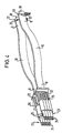
- the optical connection unit shown in Fig. 1 comprises a housing 1 with an internal cavity 2, which is made of elastic material 3, for example filled with an elastomer, silicone or the like is.
- the housing 1 has on its opposite end faces 4, 5 Openings 6, 7 through which the free ends 8, 9 of a light guide 10 protrude.
- the light guide 10 extends over the entire length of the housing 1 and through this and through the elastic material 3 so that elastic material both above and below the light guide 10 3 is present.
- the light guide 10 forms together with the elastic material 3 optical transmission element 11, wherein the at the free ends 8, 9 arranged end faces of the light guide 10 as coupling surfaces 12, 13 for optical coupling to light-conducting, receiving and / or emitting optical elements are formed.
- a button 15 is provided in a side wall 14 of the housing 1 the elastic material 3 with a force substantially perpendicular can be applied to the longitudinal axis of the light guide 10.
- the one over the button 15 onto the elastic material 3 arranged below the light guide 10 emitted force is on the light guide 10 and through this on the transferred elastic material 3 arranged above the light guide 10, so that when you press the button 15 of the light guide 10 one in Fig. 1 after takes on a curved shape at the top.
- the free Ends 8, 9 and thus also the coupling surfaces 12, 13 of the light guide 10 moved towards the inside of the housing 1. That way-that out the light guide 10 and the elastic material 3 existing optical Transmission element 11 impressed bias causes the Coupling surfaces 12, 13 are biased in the direction of arrows 16, 17.
- FIG. 2 shows the optical connection unit according to FIG. 1 without button 15.
- the optical transmission element 11 is in its biased state Position shown in which the light guide 11 has an S-shaped course and the elastic material 3 compressed and relieved accordingly Owns areas.
- the shape of the light guide 10 shown in FIG. 2 can, for example, thereby achieved that the coupling surfaces 12, 13 of the light guide 10 in the axial direction with one directed towards the interior of the housing 1 Force is applied, whereby the light guide 10 is compressed becomes.
- the coupling surfaces 12, 13 in that shown in FIG. 2 biased position moved closer to each other with typical values for the distance between the coupling surfaces 12, 13 in the relaxed Condition, for example, between 60 and 100 mm, in particular approximately 80 mm, and in the pretensioned state in each case for example between 1 and 5 mm, in particular values reduced by approx. 2 mm.
- typical Values for the maximum lateral deflection when the The light guide is between 3 and 20 mm, in particular about 8 mm.
- the optical element 18 represents, for example, an electro-optical element that is to be emitted and / or receiving light signals while the optical Element 19 is an optical mixer element with which light signals can be distributed and / or merged.
- the connection unit designed according to the invention any type of light-guiding, receiving and / or emitting to connect optical elements with each other.
- the optical element 18 has a coupling surface 20 which is used for coupling is formed on the coupling surface 13 of the light guide 10.
- the optical element 19 has a coupling surface 21, which for coupling to the coupling surface 12 of the light guide 10 is trained.
- the optical elements 18, 19 are each so on the end faces 5, 4th of the housing 1 that the coupling surfaces 13 and 20 and 12th and 21 lie flat against each other. Then the optical Elements 18, 19 continue in the direction of the housing against the arrows 17, 16 moves that the light guide 10 in the biased shown in Fig. 2 Position is spent. Due to the partially compressed elastic Material 3 thus becomes the coupling surfaces 12, 13 of the light guide 10 biased towards the outside in the direction of arrows 16, 17 and thus against the coupling surfaces 20, 21 of the optical elements 18, 19 pressed. On in this way a safe coupling of the optical elements 18, 19 reached to the light guide 10.
- the optical elements 18, 19 can in the usual way with the optical connection unit, in particular connected to the housing 1 to create a mechanically stable connection.
- the optical elements 18, 19 with the housing 1st screwed, locked or, for example, via a clamp, bayonet or Clasp fastener to be attached.
- Fig. 3 shows schematically the basic principle of the invention. It is to recognize that from the elastic material 3 and the light guide 10 formed optical transmission element 11 immediately the function has a spring element, so that with a bias of the optical Transmission element 11, the coupling surfaces 12, 13 in the direction of Arrows 16, 17 are biased. For example, if one of the optical elements 18, 19 or both optical elements 18, 19 through mechanical stress in the direction of arrows 16, 17 moves, so become the coupling surfaces 12 and 21, which abut each other or 13 and 20 are not separated from each other, but the coupling surfaces 12, 13 of the light guide 10 follow due to the bias of the Transmission element 11 of the movement of the optical element 18 or 19. Thus, within the maximum preload, one remains Movement of the optical elements 18, 19 a secure optical connection between the optical connection unit 10 and the optical Elements 18 and 19 guaranteed.
- 4 is an optical connection unit designed according to the invention shown with two flexible light guides 10. This is for simplification the representation of the housing and any existing elastic Material not shown.
- the light guide bundles 23 each consist of eight light guides 24, of which four are arranged one above the other in a row.
- the eight light guides 24 are shown in a cut-open guide block 25 merged so that their ends in a single line come to lie on top of each other. This way the ends the light guide 24 directly to the coupling surface 12 of the band-shaped Optical fiber 10 are coupled.
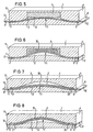
- the cavity 2 is designed that the light guide 10 is already slightly pre-bent in its relaxed position is. "Relaxed position" is not necessarily so understand that the light guide 10 is completely free of bending stress, but that the light guide 10 is relaxed as far as it is by the Structural design of the housing 1 is possible, so that the free ends 8, 9 of the light guide 10 extended as far as possible from the housing 1 are.
- FIG Fig. 6 The position of the light guide 10 biased according to the invention is shown in FIG Fig. 6 shown. This biased position is, for example, by Compression of the free ends 8, 9 of the light guide 10 is reached.
- This embodiment according to FIGS. 5 and 6 is below the minimum a minimum bending radius of the light guide 10 prevented, so that at Biasing the light guide 10 by compressing its free Ends 8, 9 the bending direction of the light guide 10 is predetermined, namely in the direction of increasing the minimum bending radius, and on the other hand, compressing the light guide 10 exclusively in the axial direction Direction without lateral deflection, as may be the case with a linear Arrangement of the light guide 10 according to FIG. 1 can occur reliably is prevented.
- the elastic element 3 consists of a Leaf spring 26, in particular a steel spring, which runs along part of the Light guide 10 runs parallel to this and in particular on this is applied.
- the ends 27, 28 of the leaf spring 26 are substantially vertical immovable to the light guide 10, parallel to the light guide 10 however, slidably disposed in the cavity 2 so that when compressed the ends 8, 9 of the light guide 10 through the leaf spring 26 the light guide 10 pressed into the biased position shown in FIG. 8 becomes.
- any suitable one can be used instead of a leaf spring Type of spring, for example a plate spring or a coil spring, is used become.
- any other can also be required
- Elastic material such as plastic, as Spring material can be used.
- the light guide 10 each have a rectangular shape Cross-section, this cross-section can in principle be any Shape, for example circular, be formed. It is only essential that a shape of the light guide 10 is selected, either by exposure a laterally acting force, for example via or more buttons 15, or by axially on the end faces of the light guide 10 acting forces can be changed so that the free ends of the light guide 10 withdrawn.
- a laterally acting force for example via or more buttons 15, or by axially on the end faces of the light guide 10 acting forces
Landscapes
- Physics & Mathematics (AREA)
- General Physics & Mathematics (AREA)
- Optics & Photonics (AREA)
- Optical Couplings Of Light Guides (AREA)
Description
- Fig. 1
- eine schematische teilweise geschnittene Perspektivdarstellung einer optischen Verbindungseinheit,
- Fig. 2
- eine Ausführungsform einer weiteren optischen Verbindungseinheit in Schnittdarstellung,
- Fig. 3
- ein schematisches Ersatzschaltbild zur Erläuterung der Funktion einer erfindungsgemäß ausgebildeten Verbindungseinheit,
- Fig. 4
- eine teilweise aufgerissene, perspektivische Darstellung einer erfindungsgemäßen optischen Verbindungseinheit,
- Fig. 5
- eine weitere Ausführungsform der Erfindung im entspannten Zustand,
- Fig. 6
- die Vorrichtung nach Fig. 5 im vorgespannten Zustand,
- Fig. 7
- eine weitere Ausführungsform der Erfindung im entspannten Zustand und
- Fig. 6
- die Vorrichtung nach Fig. 7 im vorgespannten Zustand.
- 1)
- Gehäuse
- 2)
- Hohlraum
- 3)
- elastisches Material
- 4)
- Stirnseite des Gehäuses
- 5)
- Stirnseite des Gehäuses
- 6)
- Öffnung
- 7)
- Öffnung
- 8)
- freies Ende des Lichtleiters
- 9)
- freies Ende des Lichtleiters
- 10)
- Lichtleiter
- 11)
- optisches Übertragungselement
- 12)
- Kopplungsfläche
- 13)
- Kopplungsfläche
- 14)
- Seitenwand
- 15)
- Taster
- 16)
- Pfeil
- 17)
- Pfeil
- 18)
- optisches Element
- 19)
- optisches Element
- 20)
- Kopplungsfläche
- 21)
- Kopplungsfläche
- 22)
- Enden der Lichtleiterbündel
- 23)
- Lichtleiterbündel
- 24)
- Lichtleiter
- 25)
- Führungsblock
- 26)
- Blattfeder
- 27)
- Ende der Blattfeder
- 28)
- Ende der Blattfeder
Claims (10)
- Optische Verbindungseinheit zum optisch leitenden Verbinden von Licht leitenden, aufnehmenden und/oder abgebenden optischen Elementen (19, 18, 23) wobei die optische Verbindungseinheit ein optisches Übertragungselement (11) beeinhaltet, das zumindest eine Kopplungsfläche (12, 13) zum optischen Ankoppeln an eine Kopplungsfläche (21, 20) eines der optischen Elemente (18, 19, 23) aufweist und als Federelement ausgebildet ist, so dass das Übertragungselement (11) mit seiner Kopplungsfläche (12, 13) in Richtung zu der Kopplungsfläche (21, 20) des optischen Elements (19, 18, 23) hin vorspannbar ist, wobei das Übertragungselement (11) einen flexiblen Lichtleiter (10) mit zwei Enden (8, 9) umfasst und der Lichtleiter (10) in einem Gehäuse (1) angeordnet ist,
dadurch gekennzeichnet, dass die beiden Enden (8, 9) des Lichtleiters (10) durch in dem Gehäuse (1) ausgebildete Öffnungen (6, 7) nach außen geführt sind, dass der Lichtleiter (10) auch ohne angekoppeltes optisches Element (19, 28, 23) seitlich ausgelenkt ist, und dass beim Ankoppeln von optischen Elementen (19, 28, 23) an das Übertragungselement die beiden nach außen ragenden Enden (8, 9) des Lichtleiters (10) zum Inneren des Gehäuses (1) hin bewegt werden, wodurch ein weiteres seitliches Auslenken des Lichtleiters (10) und ein Vorspannen des Übertragungselementes (11) bewirkt werden. - Optische Verbindungseinheit nach Anspruch 1,
dadurch gekennzeichnet, daß das Übertragungselement (11) zumindest zwei Kopplungsflächen (12, 13) zur Ankopplung an die optischen Elemente (19, 18, 23) aufweist. - Optische Verbindungseinheit nach Anspruch 2,
dadurch gekennzeichnet, daß die Kopplungsflächen (12, 13) durch die Stirnflächen des Lichtleiters (10) gebildet werden. - Optische Verbindungseinheit nach Anspruch 1, 2 oder 3,
dadurch gekennzeichnet, daß das Übertragungselement (11) einen elastischen Lichtleiter (10), insbesondere ein Kunststoff- oder Glasfaserkabel umfaßt. - Optische Verbindungseinheit nach einem der vorhergehenden Ansprüche,
dadurch gekennzeichnet, daß seitlich des Lichtleiters (10) elastische Elemente, insbesondere elastisches Material (3) vorgesehen ist, durch die der Lichtleiter (10) im wesentlichen in eine vorgegebene Form gedrängt wird. - Optische Verbindungseinheit nach Anspruch 5,
dadurch gekennzeichnet, daß der Lichtleiter (10) und das elastische Material (3) in einem gemeinsamen Gehäuse (1) angeordnet sind. - Optische Verbindungseinheit nach einem der vorhergehenden Ansprüche
dadurch gekennzeichnet, daß an dem Gehäuse (1) ein Betätigungsorgan (15) zum Vorspannen des Übertragungselements (11) vorgesehen ist. - Optische Verbindungseinheit nach einem der vorhergehenden Ansprüche
dadurch gekennzeichnet, daß der Lichtleiter durch das freie Ende eines Kunststoff- oder Glasfaserkabels gebildet wird. - Verwendung einer optischen Verbindungseinheit in einem optischen Netzwerk.
dadurch gekennzeichnet, dass die optische Verbindungseinheit nach einem der Ansprüche 1 bis 8 ausgebildet ist. - Verwendung nach Anspruch 9,
dadurch gekennzeichnet, dass die optische Verbindungseinheit zur Verbindung von Lichtleitern mit einem optischen Mischer (19), d.h. einem optischen Verteiler und/oder einer optischen Sammeleinheit verwendet wird.
Applications Claiming Priority (2)
| Application Number | Priority Date | Filing Date | Title |
|---|---|---|---|
| DE19826275A DE19826275A1 (de) | 1998-06-12 | 1998-06-12 | Optische Verbindungseinheit |
| DE19826275 | 1998-06-12 |
Publications (3)
| Publication Number | Publication Date |
|---|---|
| EP0964279A2 EP0964279A2 (de) | 1999-12-15 |
| EP0964279A3 EP0964279A3 (de) | 2001-09-12 |
| EP0964279B1 true EP0964279B1 (de) | 2003-11-05 |
Family
ID=7870730
Family Applications (1)
| Application Number | Title | Priority Date | Filing Date |
|---|---|---|---|
| EP99111353A Expired - Lifetime EP0964279B1 (de) | 1998-06-12 | 1999-06-10 | Optische Verbindungseinheit |
Country Status (3)
| Country | Link |
|---|---|
| US (1) | US6422762B1 (de) |
| EP (1) | EP0964279B1 (de) |
| DE (2) | DE19826275A1 (de) |
Families Citing this family (2)
| Publication number | Priority date | Publication date | Assignee | Title |
|---|---|---|---|---|
| JP3795469B2 (ja) * | 2003-03-19 | 2006-07-12 | 日本航空電子工業株式会社 | 光コネクタ |
| DE102017116347A1 (de) * | 2017-07-20 | 2019-01-24 | Huber + Suhner Ag | Wellenleitung für elektromagnetische Wellen, Wellenleiterverbinder sowie Kommunikationsverbindung |
Family Cites Families (12)
| Publication number | Priority date | Publication date | Assignee | Title |
|---|---|---|---|---|
| DE2518319C2 (de) * | 1975-04-24 | 1981-11-05 | Siemens AG, 1000 Berlin und 8000 München | Loesbare Spleissverbindung fuer Lichtwellenleiterkabel |
| US4045121A (en) | 1976-01-22 | 1977-08-30 | The Deutsch Company Electronic Components Division | Optical fiber connector |
| DE2622607C3 (de) * | 1976-05-20 | 1981-09-03 | Siemens AG, 1000 Berlin und 8000 München | Selbstzentrierende Steckverbindungsanordnung für Lichtwellenleiter |
| FR2386060A1 (fr) * | 1977-03-28 | 1978-10-27 | Connexion Ste Nle | Connecteur a tampon interfacial en elastomere pour conducteurs optiques |
| JPS559535A (en) | 1978-07-07 | 1980-01-23 | Nippon Telegr & Teleph Corp <Ntt> | Optical fiber connector |
| US4218113A (en) | 1978-08-21 | 1980-08-19 | International Business Machines Corporation | Optical fiber connector apparatus |
| US4747658A (en) * | 1983-03-14 | 1988-05-31 | International Telephone And Telegraph Corporation | Fiber optic contact |
| DE3902411A1 (de) | 1989-01-27 | 1990-08-02 | Rheydt Kabelwerk Ag | Muffe fuer lichtwellenleiter-kabel |
| FR2657697B1 (fr) | 1990-01-29 | 1993-05-07 | Radiall Sa | Connecteur pour fibres optiques. |
| WO1992019998A1 (en) | 1991-05-09 | 1992-11-12 | Itt Industries, Inc. | Fiber optic connector with abutting tips |
| US5347602A (en) * | 1992-03-04 | 1994-09-13 | Siemens Aktiengesellschaft | A device for bending a light waveguide to detect signal therein |
| US5528407A (en) * | 1993-12-27 | 1996-06-18 | Rohm Co., Ltd. | Transceiver module for optical communication |
-
1998
- 1998-06-12 DE DE19826275A patent/DE19826275A1/de not_active Withdrawn
-
1999
- 1999-05-19 US US09/314,760 patent/US6422762B1/en not_active Expired - Fee Related
- 1999-06-10 EP EP99111353A patent/EP0964279B1/de not_active Expired - Lifetime
- 1999-06-10 DE DE59907596T patent/DE59907596D1/de not_active Expired - Fee Related
Also Published As
| Publication number | Publication date |
|---|---|
| EP0964279A2 (de) | 1999-12-15 |
| US6422762B1 (en) | 2002-07-23 |
| DE59907596D1 (de) | 2003-12-11 |
| EP0964279A3 (de) | 2001-09-12 |
| DE19826275A1 (de) | 1999-12-16 |
Similar Documents
| Publication | Publication Date | Title |
|---|---|---|
| DE69223404T2 (de) | Steckverbinder für lichtwellenleiter | |
| DE69307018T2 (de) | Steckeranordnung | |
| DE3786900T2 (de) | Optischer Verbinder und dessen Herstellungsverfahren. | |
| DE69935118T2 (de) | Steckeranordnung | |
| DE2757216C3 (de) | Verbinder für optische Fasern | |
| DE10340413B4 (de) | Optischer Steckverbinder | |
| DE69917328T2 (de) | Faseroptischer Verbinder in dem eine optische Faser auch dann geschützt wird, wenn die Verbindung nicht hergestellt ist | |
| DE3107553C2 (de) | Vorrichtung zum selbsttätigen Ausrichten und Anschließen mindestens einer optischen Faserleitung in Steckverbindern | |
| EP1006378B1 (de) | Steckverbindung mit einer Mehrzahl von parallel angeordneten Lichtwellenleitern | |
| CH659529A5 (de) | Steckereinrichtung zum verbinden zumindest einer lichtleitfaser mit einem weiteren optischen element. | |
| EP0285803A2 (de) | Lichtwellenleiter-Spleissklemme | |
| DE69119922T2 (de) | Stecker für optische Fasern | |
| DE3517388A1 (de) | Anschlussteil fuer ein faser-optisches kabel | |
| DE10325825B4 (de) | Optischer Steckverbinder | |
| DE69218480T2 (de) | Lichtwellenleiterverbindung | |
| DE10255100B4 (de) | Optischer Verbinder und Anordnung zum Halten einer optischen Faserleitung | |
| DE2722612A1 (de) | Verbindung fuer lichtleitfasern mit schutzummantelung | |
| DE19845854A1 (de) | Lichtwellenleiter-Steckverbinder für eine mechanischlösbare Verbindung zwischen -mindestens einem LWL-Steckerpaar -mindestens einem LWL-Stecker und einer Leiterplatte | |
| DE112014003104T5 (de) | Optisches Verbindungselement | |
| DE4219901A1 (de) | Lichtwellenleiter-Abschlußhülse | |
| DE2933790C2 (de) | Lösbare Verbindungsvorrichtung für Lichtleiter | |
| EP0964279A2 (de) | Optische Verbindungseinheit | |
| DE10203961C1 (de) | Koppelanordnung zum Ankoppeln eines optischen Steckers mit einem Steckerstift an ein Montageröhrchen | |
| DE10253910B4 (de) | Optische Verbindervorrichtung | |
| EP1214617B1 (de) | Optischer steckverbinder |
Legal Events
| Date | Code | Title | Description |
|---|---|---|---|
| PUAI | Public reference made under article 153(3) epc to a published international application that has entered the european phase |
Free format text: ORIGINAL CODE: 0009012 |
|
| AK | Designated contracting states |
Kind code of ref document: A2 Designated state(s): AT BE CH CY DE DK ES FI FR GB GR IE IT LI LU MC NL PT SE Kind code of ref document: A2 Designated state(s): DE FR IT |
|
| AX | Request for extension of the european patent |
Free format text: AL;LT;LV;MK;RO;SI |
|
| PUAL | Search report despatched |
Free format text: ORIGINAL CODE: 0009013 |
|
| AK | Designated contracting states |
Kind code of ref document: A3 Designated state(s): AT BE CH CY DE DK ES FI FR GB GR IE IT LI LU MC NL PT SE |
|
| AX | Request for extension of the european patent |
Free format text: AL;LT;LV;MK;RO;SI |
|
| RIC1 | Information provided on ipc code assigned before grant |
Free format text: 7G 02B 6/42 A, 7G 02B 6/36 B |
|
| 17P | Request for examination filed |
Effective date: 20011108 |
|
| 17Q | First examination report despatched |
Effective date: 20011228 |
|
| AKX | Designation fees paid |
Free format text: DE FR IT |
|
| GRAH | Despatch of communication of intention to grant a patent |
Free format text: ORIGINAL CODE: EPIDOS IGRA |
|
| GRAS | Grant fee paid |
Free format text: ORIGINAL CODE: EPIDOSNIGR3 |
|
| GRAA | (expected) grant |
Free format text: ORIGINAL CODE: 0009210 |
|
| AK | Designated contracting states |
Kind code of ref document: B1 Designated state(s): DE FR IT |
|
| PG25 | Lapsed in a contracting state [announced via postgrant information from national office to epo] |
Ref country code: IT Free format text: LAPSE BECAUSE OF FAILURE TO SUBMIT A TRANSLATION OF THE DESCRIPTION OR TO PAY THE FEE WITHIN THE PRESCRIBED TIME-LIMIT;WARNING: LAPSES OF ITALIAN PATENTS WITH EFFECTIVE DATE BEFORE 2007 MAY HAVE OCCURRED AT ANY TIME BEFORE 2007. THE CORRECT EFFECTIVE DATE MAY BE DIFFERENT FROM THE ONE RECORDED. Effective date: 20031105 Ref country code: FR Free format text: LAPSE BECAUSE OF FAILURE TO SUBMIT A TRANSLATION OF THE DESCRIPTION OR TO PAY THE FEE WITHIN THE PRESCRIBED TIME-LIMIT Effective date: 20031105 |
|
| REF | Corresponds to: |
Ref document number: 59907596 Country of ref document: DE Date of ref document: 20031211 Kind code of ref document: P |
|
| PLBE | No opposition filed within time limit |
Free format text: ORIGINAL CODE: 0009261 |
|
| STAA | Information on the status of an ep patent application or granted ep patent |
Free format text: STATUS: NO OPPOSITION FILED WITHIN TIME LIMIT |
|
| 26N | No opposition filed |
Effective date: 20040806 |
|
| EN | Fr: translation not filed | ||
| PGFP | Annual fee paid to national office [announced via postgrant information from national office to epo] |
Ref country code: DE Payment date: 20070607 Year of fee payment: 9 |
|
| PG25 | Lapsed in a contracting state [announced via postgrant information from national office to epo] |
Ref country code: DE Free format text: LAPSE BECAUSE OF NON-PAYMENT OF DUE FEES Effective date: 20090101 |