EP0964200A1 - Rohrformteil - Google Patents
Rohrformteil Download PDFInfo
- Publication number
- EP0964200A1 EP0964200A1 EP99108487A EP99108487A EP0964200A1 EP 0964200 A1 EP0964200 A1 EP 0964200A1 EP 99108487 A EP99108487 A EP 99108487A EP 99108487 A EP99108487 A EP 99108487A EP 0964200 A1 EP0964200 A1 EP 0964200A1
- Authority
- EP
- European Patent Office
- Prior art keywords
- pipe
- opening
- bead
- ellipse
- molding
- Prior art date
- Legal status (The legal status is an assumption and is not a legal conclusion. Google has not performed a legal analysis and makes no representation as to the accuracy of the status listed.)
- Granted
Links
- 238000000465 moulding Methods 0.000 title claims abstract description 26
- 239000011324 bead Substances 0.000 claims description 20
- 230000007423 decrease Effects 0.000 claims description 3
- 238000010438 heat treatment Methods 0.000 description 5
- 239000004020 conductor Substances 0.000 description 2
- 238000003466 welding Methods 0.000 description 2
- 206010010774 Constipation Diseases 0.000 description 1
- 244000089486 Phragmites australis subsp australis Species 0.000 description 1
- 238000006073 displacement reaction Methods 0.000 description 1
- 238000004519 manufacturing process Methods 0.000 description 1
- 239000000463 material Substances 0.000 description 1
- 238000000034 method Methods 0.000 description 1
- 238000003825 pressing Methods 0.000 description 1
- 238000007789 sealing Methods 0.000 description 1
- 230000007704 transition Effects 0.000 description 1
Images
Classifications
-
- F—MECHANICAL ENGINEERING; LIGHTING; HEATING; WEAPONS; BLASTING
- F16—ENGINEERING ELEMENTS AND UNITS; GENERAL MEASURES FOR PRODUCING AND MAINTAINING EFFECTIVE FUNCTIONING OF MACHINES OR INSTALLATIONS; THERMAL INSULATION IN GENERAL
- F16L—PIPES; JOINTS OR FITTINGS FOR PIPES; SUPPORTS FOR PIPES, CABLES OR PROTECTIVE TUBING; MEANS FOR THERMAL INSULATION IN GENERAL
- F16L41/00—Branching pipes; Joining pipes to walls
- F16L41/004—Joining to walls at other than 90 degrees
Definitions
- the invention relates to a pipe fitting for placement on pipes, wherein in the pipe Opening is introduced, which is congruent with an opening in the pipe molding, wherein a pipe piece projecting from this opening is formed on the pipe molding, and wherein the pipe molding is open on the circumference encompassing the pipe.
- connection is only rectangular pipes running to each other can be connected. Once the to be connected Pipes run at a certain angle to each other, it is necessary to describe them Form of the connection to integrate additional molded parts and thus additional To incur costs.
- the opening in the tubular molded part has an elliptical shape has at its one free end of a larger in size
- Half-ellipse is superimposed on that around the half-ellipse a bead integrally into the lumen of the Pipe molded part is integrally formed, the height of which is at least the wall thickness of the tube corresponds and whose thickness decreases continuously from the vertices to the apex, whereby their outer circumference corresponds to at least one semicircle that the bead with their outer circumference bears against the wall of the pipe opening, and that in the lumen of the Pipe protruding part of the bead is provided with a radius.
- the advantage here is that the bead radially in the opening of the pipe to be connected Tube fixed.
- the selected saddle-shaped geometry of the lower part of the tubular molded part is advantageous achieved a holding function by the clasp, while at the same time the force to assemble the pipe fitting is minimized.
- the one in the lumen of the to be connected Pipe protruding part of the bead, which is provided with the radius, ensures one smooth transition from the pipe molding to the pipe to be connected, so that it is here is advantageously possible, in addition to the flow of media, cables and the like relocate.
- the axial fixing element according to the invention at the apex of the opening in the pipe molding guarantees axial fixation in connection with the bead.
- the opening in the pipe to be connected is made with a separate tool, without chips or other residues getting into the lumen of the pipe to be connected.
- the saddle-shaped geometry of the lower part and the wall thickness of the complete Pipe shaped part was optimized so that a minimal use of material and thus significant Cost advantages over the known prior art can be realized can.
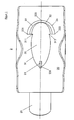
- the pipe molding 2 is in Figure 1, consisting of the lower part 20 and the protruding Pipe piece 21 shown.
- the Shown opening 30 On the inner wall of the lower part 20 of the tubular part 2 is the Shown opening 30, which has an elliptical shape 31. At the free ends of the ellipse 311, 312 this is overlaid by a larger semi-ellipse 32.
- the bead 22 Around the semi-ellipse is 32 the bead 22 is shown, which protrudes into the lumen of the tubular molding 2.
- the outer The circumference 24 of the bead 22 corresponds to a semicircle.
- the thickness of the bead 22 decreases from that Corner points 221, 222 to the apex 220 continuously from.
- Diametrically to that at the Half-ellipse 32 located bead 22 is a fixing element 23 in one piece at the apex 231 of the ellipse 31 formed.
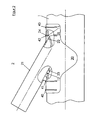
- FIG. 2 shows a connection between the pipe 1 and the pipe molding 2. It can be seen that that the lower part 20 of the tubular part 2 engages around the tube 1 and the upper part 21 of the pipe molding 2 protrudes from the pipe 1 at a certain angle.
- the bead 22 lies with its outer semicircular circumference 24 directly on the wall 11 of the pipe opening of the pipe 1.
- the height of the bead 22 corresponds in this embodiment the wall thickness of the tube 1.
- the protruding into the lumen of the tube 1 Part of the bead 22 of the tubular part 2 is provided with a radius 25.
- the axial fixing element 23 can be seen, which is in this Embodiment was chosen triangular and the diametrical to the bead 22 on the Wall 12 of the pipe opening of the pipe 1 abuts. This is an axial displacement of the Pipe molding 2 on pipe 1 not possible.
- the circumferential collar 40, 41 and 42, 43 attached in one piece, between which a strap can be attached all around.
Landscapes
- Engineering & Computer Science (AREA)
- General Engineering & Computer Science (AREA)
- Mechanical Engineering (AREA)
- Branch Pipes, Bends, And The Like (AREA)
- Rigid Pipes And Flexible Pipes (AREA)
- Non-Disconnectible Joints And Screw-Threaded Joints (AREA)
- Supports For Pipes And Cables (AREA)
- Protection Of Pipes Against Damage, Friction, And Corrosion (AREA)
Abstract
Description
Nachteilig wird in diesem Schutzrecht erwähnt, daß die Heizmatte und deren metallischer Heizleiter im Anschluß an die geschaffene Verbindung durchbohrt werden müssen. Dabei können einzelne Heizleiterstücke aus der geschaffenen Verbindung herausgelöst werden und mit den Durchflußmedien in Kontakt kommen.
- Figur 1
- eine Ansicht von unten auf das Rohrformteil.
- Figur 2
- eine Seitenansicht mit partieller Schnittdarstellung des Rohrformteiles und eines Rohres.
Claims (2)
- Rohrformteil zum Aufsetzen auf Rohre, wobei in das Rohr eine Öffnung eingebracht ist, die deckungsgleich zu einer Öffnung im Rohrformteil ist, wobei an das Rohrformteil ein von dieser Öffnung wegragendes Rohrstück angeformt ist, und wobei das Rohrformteil an dem das Rohr umgreifenden Umfang offen ist,
dadurch gekennzeichnet,
daß die Öffnung (30) im Rohrformteil (2) eine Ellipsenform (31) aufweist, die an ihrem einen freien Ende von einer in den Abmessungen größeren Halbellipse (32) überlagert ist, daß um die Halbellipse (32) eine Wulst (22) einstückig in das Lumen des Rohrformteiles (2) ragend angeformt ist, deren Höhe wenigstens der Wandstärke des Rohres (1) entspricht und deren Dicke von den Eckpunkten (221, 222) zum Scheitel (220) kontinuierlich abnimmt, wobei ihr äußerer Umfang (24) wenigstens einem Halbkreis entspricht, daß die Wulst (22) mit ihrem äußeren Umfang (24) an der Wandung (11) der Rohröffnung anliegt, und daß der in das Lumen des Rohres (1) hineinragende Teil der Wulst (22) mit einem Radius (25) versehen ist. - Rohrformteil nach Anspruch 1, dadurch gekennzeichnet, daß diametral zu der Wulst (22) der Halbellipse (32) ein axiales Fixierelement (23) einstückig am Scheitelpunkt (231) der Ellipse (31) im Rohrformteil (2) angeformt ist.
Applications Claiming Priority (2)
| Application Number | Priority Date | Filing Date | Title |
|---|---|---|---|
| DE29810294U DE29810294U1 (de) | 1998-06-09 | 1998-06-09 | Rohrformteil |
| DE29810294U | 1998-06-09 |
Publications (2)
| Publication Number | Publication Date |
|---|---|
| EP0964200A1 true EP0964200A1 (de) | 1999-12-15 |
| EP0964200B1 EP0964200B1 (de) | 2002-04-10 |
Family
ID=8058281
Family Applications (1)
| Application Number | Title | Priority Date | Filing Date |
|---|---|---|---|
| EP99108487A Expired - Lifetime EP0964200B1 (de) | 1998-06-09 | 1999-04-30 | Verbindung eines Rohrformteils mit einem Rohr |
Country Status (3)
| Country | Link |
|---|---|
| EP (1) | EP0964200B1 (de) |
| AT (1) | ATE216047T1 (de) |
| DE (2) | DE29810294U1 (de) |
Citations (3)
| Publication number | Priority date | Publication date | Assignee | Title |
|---|---|---|---|---|
| DE7101299U (de) * | 1970-01-16 | 1971-06-03 | Soc Del Gres Ing Sala & C Spa | Vorrichtung zur Fertigung von Abzwei gungen in Rohrleitungen aus plastischem Material |
| CH557981A (de) * | 1973-08-29 | 1975-01-15 | Schmidlin Ag | Anschlussstueck zum anschluss einer zweigleitung an eine hauptleitung. |
| US4438955A (en) * | 1982-01-21 | 1984-03-27 | Wfi International, Inc. | Acute angled vessel connector |
Family Cites Families (2)
| Publication number | Priority date | Publication date | Assignee | Title |
|---|---|---|---|---|
| DE1870240U (de) | 1963-01-14 | 1963-04-11 | Kabel U Gummiwerke A G Manufac | Abzweigungsanordnung fuer kunststoffrohre. |
| GB1442624A (en) | 1972-08-11 | 1976-07-14 | Nyloplast Bv | Branch connection on a tube of synthetic material |
-
1998
- 1998-06-09 DE DE29810294U patent/DE29810294U1/de not_active Expired - Lifetime
-
1999
- 1999-04-30 EP EP99108487A patent/EP0964200B1/de not_active Expired - Lifetime
- 1999-04-30 DE DE59901166T patent/DE59901166D1/de not_active Expired - Fee Related
- 1999-04-30 AT AT99108487T patent/ATE216047T1/de not_active IP Right Cessation
Patent Citations (3)
| Publication number | Priority date | Publication date | Assignee | Title |
|---|---|---|---|---|
| DE7101299U (de) * | 1970-01-16 | 1971-06-03 | Soc Del Gres Ing Sala & C Spa | Vorrichtung zur Fertigung von Abzwei gungen in Rohrleitungen aus plastischem Material |
| CH557981A (de) * | 1973-08-29 | 1975-01-15 | Schmidlin Ag | Anschlussstueck zum anschluss einer zweigleitung an eine hauptleitung. |
| US4438955A (en) * | 1982-01-21 | 1984-03-27 | Wfi International, Inc. | Acute angled vessel connector |
Also Published As
| Publication number | Publication date |
|---|---|
| ATE216047T1 (de) | 2002-04-15 |
| DE59901166D1 (de) | 2002-05-16 |
| EP0964200B1 (de) | 2002-04-10 |
| DE29810294U1 (de) | 1998-08-13 |
Similar Documents
| Publication | Publication Date | Title |
|---|---|---|
| DE69002015T2 (de) | Verbindungssystem zum Verschweissen von ineinandersteckbaren rohrförmigen Teilen. | |
| DE2514827A1 (de) | Anbohrformstueck aus schweissbarem kunststoff | |
| EP0913534A1 (de) | Spül- und Kontroll-Schacht für Flüssigkeitsleitungen und Schacht-Abschnitt hierfür | |
| EP0093328B1 (de) | Anschluss-Formstück | |
| DE202013003600U1 (de) | Kabelverschraubung mit integralem Gelenk | |
| DE8519523U1 (de) | Steckkupplung | |
| DE60205641T2 (de) | Zur verbindung zweier röhrenförmiger elemente verwendete kupplung und montageverfahren dafür | |
| DE2340792A1 (de) | Rohrabzweig, insbesondere fuer kunststoffrohre | |
| EP2171336B1 (de) | Rohrverbindung mit einem gehäuse einer armatur | |
| DE3446360A1 (de) | Verfahren zur herstellung eines kupplungselements zur gewaehrleistung der verbindung zwischen einer hauptleitung und einer abzweigungsleitung | |
| EP0319746A1 (de) | Vorrichtung zum gegenseitigen Verbinden von zwei Leitungen, insbesondere Kraftstoffleitungen | |
| EP0061569A1 (de) | Muffe | |
| DE8910407U1 (de) | Rohrstück und zugehörender Elektroschweißfitting | |
| DE2733571C2 (de) | Winkelveränderbares Kniestück | |
| EP0964200B1 (de) | Verbindung eines Rohrformteils mit einem Rohr | |
| DE4003906C2 (de) | Vorrichtung zum Durchführen eines Rohres durch eine biegsame Dachdichtungsbahn | |
| EP1610049B1 (de) | Schlauchverbindungssystem für einen beheizbaren Schlauch | |
| EP0089638B1 (de) | Durchgangskupplung für Rohrleitungen oder Schläuche | |
| DE9107311U1 (de) | Schweißmuffe | |
| DE19936413C1 (de) | Schlauchanschluß | |
| EP3584487B1 (de) | Abgassystem mit rohrbride | |
| DE4103702C1 (de) | ||
| DE202014003776U1 (de) | Kunststoffrohr | |
| EP0131086B1 (de) | Dachentlüftungsrohr | |
| EP0414641B1 (de) | Fixpunktbefestigung an einer Rohrleitung |
Legal Events
| Date | Code | Title | Description |
|---|---|---|---|
| PUAI | Public reference made under article 153(3) epc to a published international application that has entered the european phase |
Free format text: ORIGINAL CODE: 0009012 |
|
| AK | Designated contracting states |
Kind code of ref document: A1 Designated state(s): AT BE DE DK |
|
| AX | Request for extension of the european patent |
Free format text: AL;LT;LV;MK;RO;SI |
|
| 17P | Request for examination filed |
Effective date: 20000614 |
|
| AKX | Designation fees paid |
Free format text: AT BE DE DK |
|
| GRAG | Despatch of communication of intention to grant |
Free format text: ORIGINAL CODE: EPIDOS AGRA |
|
| RTI1 | Title (correction) |
Free format text: CONNECTION OF A TUBULAR MOLDING ELEMENT WITH A TUBE |
|
| 17Q | First examination report despatched |
Effective date: 20011108 |
|
| GRAG | Despatch of communication of intention to grant |
Free format text: ORIGINAL CODE: EPIDOS AGRA |
|
| GRAH | Despatch of communication of intention to grant a patent |
Free format text: ORIGINAL CODE: EPIDOS IGRA |
|
| GRAH | Despatch of communication of intention to grant a patent |
Free format text: ORIGINAL CODE: EPIDOS IGRA |
|
| GRAA | (expected) grant |
Free format text: ORIGINAL CODE: 0009210 |
|
| AK | Designated contracting states |
Kind code of ref document: B1 Designated state(s): AT BE DE DK |
|
| REF | Corresponds to: |
Ref document number: 216047 Country of ref document: AT Date of ref document: 20020415 Kind code of ref document: T |
|
| PG25 | Lapsed in a contracting state [announced via postgrant information from national office to epo] |
Ref country code: BE Free format text: LAPSE BECAUSE OF NON-PAYMENT OF DUE FEES Effective date: 20020430 |
|
| REF | Corresponds to: |
Ref document number: 59901166 Country of ref document: DE Date of ref document: 20020516 |
|
| PG25 | Lapsed in a contracting state [announced via postgrant information from national office to epo] |
Ref country code: DK Free format text: LAPSE BECAUSE OF FAILURE TO SUBMIT A TRANSLATION OF THE DESCRIPTION OR TO PAY THE FEE WITHIN THE PRESCRIBED TIME-LIMIT Effective date: 20020710 |
|
| PLBE | No opposition filed within time limit |
Free format text: ORIGINAL CODE: 0009261 |
|
| STAA | Information on the status of an ep patent application or granted ep patent |
Free format text: STATUS: NO OPPOSITION FILED WITHIN TIME LIMIT |
|
| 26N | No opposition filed |
Effective date: 20030113 |
|
| PGFP | Annual fee paid to national office [announced via postgrant information from national office to epo] |
Ref country code: AT Payment date: 20050310 Year of fee payment: 7 |
|
| PG25 | Lapsed in a contracting state [announced via postgrant information from national office to epo] |
Ref country code: AT Free format text: LAPSE BECAUSE OF NON-PAYMENT OF DUE FEES Effective date: 20060430 |
|
| PGFP | Annual fee paid to national office [announced via postgrant information from national office to epo] |
Ref country code: DE Payment date: 20070430 Year of fee payment: 9 |
|
| PG25 | Lapsed in a contracting state [announced via postgrant information from national office to epo] |
Ref country code: DE Free format text: LAPSE BECAUSE OF NON-PAYMENT OF DUE FEES Effective date: 20081101 |