EP0963801A2 - Presse zur Herstellung variabler Bearbeitungsmuster - Google Patents
Presse zur Herstellung variabler Bearbeitungsmuster Download PDFInfo
- Publication number
- EP0963801A2 EP0963801A2 EP99110928A EP99110928A EP0963801A2 EP 0963801 A2 EP0963801 A2 EP 0963801A2 EP 99110928 A EP99110928 A EP 99110928A EP 99110928 A EP99110928 A EP 99110928A EP 0963801 A2 EP0963801 A2 EP 0963801A2
- Authority
- EP
- European Patent Office
- Prior art keywords
- tool
- press according
- press
- punch
- contact surface
- Prior art date
- Legal status (The legal status is an assumption and is not a legal conclusion. Google has not performed a legal analysis and makes no representation as to the accuracy of the status listed.)
- Granted
Links
Images
Classifications
-
- B—PERFORMING OPERATIONS; TRANSPORTING
- B21—MECHANICAL METAL-WORKING WITHOUT ESSENTIALLY REMOVING MATERIAL; PUNCHING METAL
- B21D—WORKING OR PROCESSING OF SHEET METAL OR METAL TUBES, RODS OR PROFILES WITHOUT ESSENTIALLY REMOVING MATERIAL; PUNCHING METAL
- B21D28/00—Shaping by press-cutting; Perforating
- B21D28/24—Perforating, i.e. punching holes
- B21D28/246—Selection of punches
Definitions
- the invention relates to a press, in particular a perforating press for shaping changeable patterns in preferably flat workpieces.
- DE 4135787 A1 discloses a punch press with a Known tool, in its upper tool punch are arranged in two rows. The two rows are there straight and transverse to the direction of transport of a sheet to be punched. The one in the Upper tool punch held parallel to each other stand on gap, i.e. the punches of some Row are related to the punch temple of the other row on the transport direction of the workpieces, for example offset by half a lateral distance.
- the punches are parallel with their longitudinal direction aligned to the working direction of the upper tool and adjustable stored in it.
- each one slidably mounted transversely to the punch Locking bolts are the punch in their advanced Lockable active position.
- the latch will be on the side the punch are released and can when the top tool moves towards the workpiece, Place on the workpiece and from there into the upper tool can be pressed without a punching process takes place.
- the actuating movement is formed on the locking member Investment or restricted area with a counter abutment area in and transferred out of the plant. Are the two surface in the system, the tool part is locked in the active position. Otherwise it is released.
- the actuating movement of the locking member are significantly shortened, i.e. turn out short-stroke without the surface area of the Contact area or the counter contact area reduced overall and thus the surface pressure would be increased.
- the of the total area required for dimensioning is therefore on many subareas divided that a sufficiently short Hub is obtained.
- a short-stroke actuating movement enables then a faster adjustment of the locking member from its locked position to the release position and vice versa.
- the Contact surface on the locking member for example a locking bolt or a locking cam formed while the counter abutment surface on the adjustable tool part, i.e. For example, on a punch or on one with the punch connected intermediate piece (pressure member) is trained.
- the counter surface of the locking bolt or other locking member forms the abutment for the contact surface of the adjustable tool part.
- the contact surface to the To provide a locking member, whereas the counter abutment surface on one immovably connected to the upper tool Part or is formed on the upper tool itself.
- the locking element E.g. is this through formed a slide, which is facing away from the stamp Side is interrupted by recesses Has contact surface.
- the one provided on the top tool Counter bearing surface is also through recesses interrupted. The axial movement can be adjusted by lateral adjustment the punch and the associated locking member can now be released or blocked.
- each locking member be provided with its own drive device to to be able to adjust the locking member individually if necessary. Due to the adjustment movement required only in short stroke can use relatively underperforming drives Find. E.g. can magnetic drives so small designed to be fully in the top tool or parts of it. This is especially true if the contact surface and the counter contact surface in more than two surface areas are divided.
- the buffer element can be a rubber buffer that if the punch in question is active from the punch is easily overcome, whereas it is his Compliancy is such that he is the weight and Inertial forces of the tool part or punch under Preventing workpiece contact can pick up when the relevant tool part is not active.
- Embodiment are the locking members and the adjustable Tool part in separable part tools arranged, for example, in cassettes.
- stamps i.e. different punch diameters, Stamp forms, stamp numbers changed without the unit with the bolts and the drives switch.
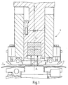
- a press 1 is cut and schematically illustrated.
- the press is used to punch variable hole patterns in a workpiece 2, the For example, is formed by a sheet that is not one further illustrated transport device in the transport direction T gradually through a tool 3 the Press 1 is moved.
- the tool 3 has an upper tool 4 and a lower tool 5. While the lower tool 5 is fixedly mounted on a press table 6, is the upper tool 4 on a not illustrated Press ram held by a drive device a back and forth indicated by an arrow 7 experienced working movement. As indicated by arrow 7 indicated, the working direction (arrow 7) of the Press ram and the upper tool 4 essentially perpendicular to the transport direction T of the workpiece 2.
- the upper tool 4 has two rows of punches 11, 11 'with which the desired hole pattern in the Workpiece 2 can be punched. Because of the construction of the upper tool 4, reference is made to FIG.
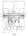
- the top tool 4 is vertical and transverse to the direction of transport T directed plane E is formed symmetrically. The following description of the left-hand side in FIG Area or section of the upper tool 4 therefore applies accordingly to the right-hand section. Its parts are only for distinction with otherwise the same reference numerals as the left part the upper tool 4 provided.
- the stamp 11 is in a stamp holder plate 14 displaceable with little play with respect to its axial direction 15 stored.
- the stamp holder plate 14 is in corresponding Sidewalls 16, 16 'of the upper tool 4 held. For this purpose, these have an approximately U-shaped cross section Recording groove 17, 17 'on, which is transverse to the transport direction T and horizontally across the entire width of the extends each cheek.
- the stamp holder plate 14 has corresponding ribs 18, 18 ', which in the grooves 17, 17 'grab and store the stamp holder plate 14.
- stamp 11 in a corresponding receiving hole the stamp holder plate 14 sits, instructs a head at its upper end facing away from the workpiece 2 21, whose diameter is slightly larger than that remaining punch 11.
- the head 21 forms with a corresponding ring shoulder 22 of the receiving bore Slings. If the head 21 lies on the ring shoulder 22 the punch 11 has its most advanced Position reached. This is his working or Asset position.
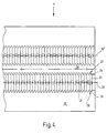
- the intermediate piece 24 has, as in FIG. 4 shows a rectangular cross-section in plan view on, its narrow sides (vertical) with guide strips 25, 26 are provided. This engages in corresponding Guide grooves 27, 28 in the cheek 16 and formed opposite in a guide part 29 are.
- the individual intermediate pieces 24 of each punch 11 are identical to one another and, for example, by Get cut to length from a suitable profile material. They are in the guide grooves 27, 28 with little play led and have a distance of a few from each other tenths of a millimeter.
- the punch 11 With her essentially plan bottom 31 are the pressure members 24 with the end faces of the heads 21 of the punch 11 in the middle of the plant.
- the punch 11 is on an approximately straight one or, as can be seen from FIG. 4, zigzag-shaped row 32 arranged.
- the diameter the heads 21 of the punch 11 correspond approximately to that Thickness of pressure members 24.
- the pressure members 24 by spring means, such as two coil springs 34, 35 biased towards the punch 11. Press with it the coil springs 34, 35 the pressure members 24 after below that the punch 11 is resilient to its working position are biased towards.
- spring means such as two coil springs 34, 35 biased towards the punch 11. Press with it the coil springs 34, 35 the pressure members 24 after below that the punch 11 is resilient to its working position are biased towards.
- the pressure members 24 with a counter abutment surface 36 provided by several in the present example is interrupted by three transverse recesses 37.
- the counter abutment surface 36 is thus by four surface areas 36a, 36b, 36c, 36d are formed, each essentially are plan and on a common level lie.
- the gaps between the surface areas 36a, 36b, 36c, 36d are each transverse to the longitudinal direction 15 measured about the same size as the surface areas or slightly larger than this.
- the depth of the gaps or recesses is at least as large as the stroke of the Punch 11 between its active position and its Passive position in which he stands, if that Upper tool 4 has reached its bottom dead center position and it does not deform the workpiece.
- the contact areas are 36a to 36d correspondingly at end faces Fingers trained. Are between your fingers Gaps formed that are at least as big as fingers.
- the distances between the surface areas 45a to 45d are in turn dimensioned such that the end faces 36a to 36d fingers of the pressure member 24 in the gaps Drive in between the contact surface areas 45a to 45d can.
- the depth is the adjustment path of the punch 11 dimensioned accordingly.
- the side ribs 43, 44 and the width of the Locking member 42 are dimensioned so that this in one Figure 2 by an arrow 47 adjustment direction can be pushed back and forth at least by a width are that of the extent measured in this direction each area corresponds to 45a to 45d.
- the surface areas To this extent, 45a to 45d are among themselves chosen the same size.
- each locking member 42 is in each case connected to a drive device 51.
- Magnetic coil 52 which is arranged in a fixed manner in the side cheek 16 is.
- the magnet coil 52 is axially displaceable an anchor 53 connected to the locking member 42, which is drawn into the coil 42 when it is excited becomes. If the armature is polarized accordingly, it can be used reverse excitation can be pushed out of the coil.
- a spring means such as a Tension spring or a spring tongue can be provided between the upper tool 4 and the locking member 42 acts. If necessary, a fluid drive can also be used.
- This enables an outside diameter of individual drive devices 51a to 51c, which up to is three times the corresponding thickness of the Locking members 42. If there is a further lack of space, the Drive devices not only triple, but also be staggered four or more times. It will possible that existing on the side of the locking members 42 To use the volume in such a way that the drive devices 51 are completely accommodated in the upper tool 4. As a result, a sheet metal holder can be guided past the upper tool 4 become.
- the punch 11, 11 'of the two rows 32, 32' are transverse to the direction of transport T against each other offset half a punch distance. With that leaves as will be seen later, not only a variable hole pattern, but if necessary also a achieve a continuous cut on the workpiece 2.
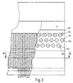
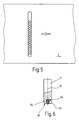
- a single punch 11 is cut out illustrated.
- the punch 11 is a essentially cylindrical or otherwise in cross section trained rod with its head 21 in the Stamp holder plate 14 is mounted.
- the free end of the punch has a substantially aligned orthogonally to its longitudinal central axis 15
- End surface 61 which is surrounded by a cutting edge 62 is.
- the end surface 61 is approximately in the middle of a blind bore 63 interrupted, in which a rubber buffer 64 sits.
- This is made of a wear and abrasion resistant elastic Material formed from the blind bore 63rd preferably protrudes in a curvature.
- the elasticity and the size of the rubber buffer 64 are such that the cutting edge 62 of the punch 11 the workpiece 2 not touched when the punch 11 is not in his Working position is locked. However, it is in this locked, the rubber buffer 64 can by the force of the Punch 11 can be easily overcome, so that Cutting edge 62 penetrates the workpiece 2 unhindered.
- the one from that Rubber buffer 64 is applied elastic force, however larger than that for braking the pressure member 24 and the Hole punch 11 needed to overcome the inertia Force plus that of the coil springs 34, 35 exerted force. So neither the cutting edge gets 62 another section or part of the punch 11 in engagement with the workpiece 2.
- the punch 11 presses near the bottom dead center of the upper tool 4 the pressure member 24 briefly upwards, so that his fingers in the interstices of the locking member 42 drive.
- the coil springs 34, 35 relax again and the pressure member 24 sets with its lower flat surface on the punch holder plate 14.
- the head 21 of the relevant punch 24 is now on the ring shoulder 22 on and is thus taken up again.
- the same applies to the active punch 11, 11 ' by placing the head 21 on the annular shoulder 22 the holes they punched are pulled out.
- any hole patterns can be because of the overlap the punch in the transport direction T and with the corresponding Control of a feed with half steps also produce larger through openings, whose outer boundary is programmable.
- the programming can, for example, by reading a template using a scanner and a corresponding control unit take place.
- punching is preferably each tool part 11 each assigned a locking member 42, the Locking member 42 has a locking and a release position.
- a contact surface 45 is provided on the locking member 42, which are divided into surface areas 45a to 45d is. Are between the surface areas 45a to 45d Recesses formed. The essentially flat and if necessary, slightly bevelled contact surfaces at their edges 45a to 45d thus form the end faces of one Gearing.
- a complementary toothing is on that Tool part 11 or one in connection with this standing pressure member 24 formed. The required Stroke of the locking element when it is transferred from Sperrin Release position and vice versa can thus on the Tooth width can be limited.
Landscapes
- Engineering & Computer Science (AREA)
- Mechanical Engineering (AREA)
- Perforating, Stamping-Out Or Severing By Means Other Than Cutting (AREA)
- Rotary Switch, Piano Key Switch, And Lever Switch (AREA)
- Press Drives And Press Lines (AREA)
- Sampling And Sample Adjustment (AREA)
- Presses And Accessory Devices Thereof (AREA)
Abstract
Description
Claims (18)
- Presse (1), insbesondere Perforierpresse zum Stanzen oder Formen veränderbarer Muster in flächenhafte Werkstücke (2),mit einem Werkzeug (3), dessen Oberwerkzeug (4) an einem Pressenstößel gehalten ist, der zur Ausführung einer Arbeitsbewegung von einem Pressenantrieb in Arbeitsrichtung (7) angetrieben ist,mit wenigstens einem an dem Oberwerkzeug (4) vorgesehenen Werkzeugteil (11, 24), das zwischen einem Aktivzustand und einem Passivzustand umschaltbar ist, wobei es in seinem Aktivzustand in einer Verstellrichtung arretiert ist, undmit einer Arretierungseinrichtung (42, 51), mit der das Werkzeugteil (11, 24) in einer Arbeitsposition arretierbar ist und die ein bewegbares Sperrglied (42) aufweist, das eine Anlagefläche (45) aufweist, die mit einer Gegenanlagefläche (36) in und außer Anlage überführbar ist,
dadurch gekennzeichnet,dass die Anlagefläche (45) in wenigstens zwei Flächenbereiche (45a, 45b) unterteilt ist und dass die Gegenanlagefläche (36) ebenfalls in wenigstens zwei Flächenbereiche (36a, 36b) unterteilt ist. - Presse nach Anspruch 1, dadurch gekennzeichnet, dass das Sperrglied (42) quer (47) zu der Verstellrichtung des Werkzeugteils (11, 24) bewegbar ist.
- Presse nach Anspruch 1, dadurch gekennzeichnet, dass die Anlagefläche (45) und die Gegenanlagefläche (36) in einer Richtung (47) unterteilt sind, die quer zu der Verstellrichtung (15) des Werkzeugteils (11, 24) ausgerichtet ist.
- Presse nach Anspruch 1, dadurch gekennzeichnet, dass zu dem Werkzeugteil (11, 24) ein Stempel (11) gehört, dessen Längsrichtung (15) mit der Verstellrichtung übereinstimmt.
- Presse nach Anspruch 1, dadurch gekennzeichnet, dass zu dem Werkzeugteil (11, 24) ein Druckglied (24) gehört, an dem die Gegenanlagefläche (36) ausgebildet ist, die mit der Anlagefläche (45) des Sperrglieds (42) in Anlage überführbar ist.
- Presse nach Anspruch 1 oder 5, dadurch gekennzeichnet, dass die Gegenanlagefläche (36) an dem Werkzeugteil (11,2 4), insbesondere dem Druckglied (24), ausgebildet ist.
- Presse nach Anspruch 1, dadurch gekennzeichnet, dass die Gegenanlagefläche (36) bezüglich des verstellbaren Werkzeugteils (11, 24) ortsfest ausgebildet ist.
- Presse nach Anspruch 1, dadurch gekennzeichnet, dass das Sperrglied (42) mit einer Antriebseinrichtung (51) verbunden ist, die willkürlich ansteuerbar ist.
- Presse nach Anspruch 1, dadurch gekennzeichnet, dass das Werkzeugteil (11, 24) federnd auf seine Position in vorgespannt ist, die es in seinem Aktivzustand einnimmt.
- Presse nach Anspruch 1, dadurch gekennzeichnet, dass das Werkzeugteil (11, 24) an seiner dem Werkstück (2) zugewandten Endfläche ein Pufferelement (64) aufweist.
- Presse nach Anspruch 1, dadurch gekennzeichnet, dass das Pufferelement (64) ein Gummipuffer ist.
- Presse nach Anspruch 1, dadurch gekennzeichnet, dass an dem Oberwerkzeug (4) mehrere verstellbare Werkzeugteile (11, 24, 11', 24') angeordnet sind.
- Presse nach Anspruch 12, dadurch gekennzeichnet, dass die Werkzeugteile (11) in einer Reihe (32), bspw. in einer geraden Reihe oder in einer Zick-Zack-Reihe angeordnet sind.
- Presse nach Anspruch 1, dadurch gekennzeichnet, dass die Reihe (32) bezogen auf eine Werkstückbewegungsrichtung (T) im Wesentlichen quer ausgerichtet ist.
- Presse nach Anspruch 8 und 13, dadurch gekennzeichnet, dass jedes Sperrglied (42) mit jeweils einer Antriebseinrichtung (51) verbunden ist und dass die Antriebseinrichtungen (51a, 51b, 51c) benachbarter Sperrglieder (24) gegeneinander vorzugsweise bezüglich der Verstellrichtung der Werkzeugteile (15) versetzt angeordnet sind.
- Presse nach Anspruch 1, dadurch gekennzeichnet, dass die Sperrglieder (42) und die verstellbaren Werkzeugteile (11, 24) in voneinander trennbaren Teilwerkzeugen (14, 16, 29) angeordnet sind.
- Presse nach Anspruch 1, dadurch gekennzeichnet, dass die Sperrglieder (42) in Verstellrichtung (15), d.h. quer zu ihrer eigenen Bewegungsrichtung (47) geführt sind.
- Presse nach Anspruch 1, dadurch gekennzeichnet, dass die Verstellrichtung der Werkzeugteile (11, 24) mit der Arbeitsrichtung (7) des Oberwerkzeugs (4) übereinstimmt.
Applications Claiming Priority (2)
| Application Number | Priority Date | Filing Date | Title |
|---|---|---|---|
| DE19825842 | 1998-06-10 | ||
| DE19825842A DE19825842A1 (de) | 1998-06-10 | 1998-06-10 | Presse zur Herstellung variabler Bearbeitungsmuster |
Publications (3)
| Publication Number | Publication Date |
|---|---|
| EP0963801A2 true EP0963801A2 (de) | 1999-12-15 |
| EP0963801A3 EP0963801A3 (de) | 2001-04-18 |
| EP0963801B1 EP0963801B1 (de) | 2004-02-25 |
Family
ID=7870463
Family Applications (1)
| Application Number | Title | Priority Date | Filing Date |
|---|---|---|---|
| EP99110928A Expired - Lifetime EP0963801B1 (de) | 1998-06-10 | 1999-06-04 | Presse zur Herstellung variabler Bearbeitungsmuster |
Country Status (4)
| Country | Link |
|---|---|
| EP (1) | EP0963801B1 (de) |
| AT (1) | ATE260155T1 (de) |
| CZ (1) | CZ203099A3 (de) |
| DE (2) | DE19825842A1 (de) |
Cited By (3)
| Publication number | Priority date | Publication date | Assignee | Title |
|---|---|---|---|---|
| CN103253054A (zh) * | 2012-02-06 | 2013-08-21 | 菲斯科尔思品牌有限公司 | 用于在片材中形成图案的装置 |
| CN110027352A (zh) * | 2019-05-22 | 2019-07-19 | 温州岑泰机械有限公司 | 一种成型盒压纹机的新型压纹机构 |
| WO2020156606A3 (de) * | 2019-02-01 | 2020-10-01 | WISTA Werkzeugfertigungs-GmbH | Stanz-/perforiermaschine |
Families Citing this family (1)
| Publication number | Priority date | Publication date | Assignee | Title |
|---|---|---|---|---|
| DE10328776B3 (de) * | 2003-06-25 | 2005-01-27 | Groz-Beckert Kg | Stanzvorrichtung für flächige Gegenstände |
Citations (4)
| Publication number | Priority date | Publication date | Assignee | Title |
|---|---|---|---|---|
| DE2741537A1 (de) * | 1977-09-15 | 1979-03-22 | Cis Metalform Masch | Verfahren zur herstellung von teilen |
| FR2407765A1 (fr) * | 1977-11-08 | 1979-06-01 | Thomson Brandt | Procede et dispositif de fabrication de toles perforees notamment pour viroles de tambours de machines a laver |
| DE3935498A1 (de) * | 1989-10-25 | 1991-05-02 | Innovations Projekte Ag | Verfahren zum bearbeiten von werkstuecken und presseinrichtung zur ausuebung des verfahrens |
| US5357446A (en) * | 1990-11-08 | 1994-10-18 | Sankyo Kogyo Co., Ltd. | Punching machining device for plates |
-
1998
- 1998-06-10 DE DE19825842A patent/DE19825842A1/de not_active Withdrawn
-
1999
- 1999-06-04 EP EP99110928A patent/EP0963801B1/de not_active Expired - Lifetime
- 1999-06-04 DE DE59908618T patent/DE59908618D1/de not_active Expired - Lifetime
- 1999-06-04 AT AT99110928T patent/ATE260155T1/de not_active IP Right Cessation
- 1999-06-07 CZ CZ992030A patent/CZ203099A3/cs unknown
Patent Citations (4)
| Publication number | Priority date | Publication date | Assignee | Title |
|---|---|---|---|---|
| DE2741537A1 (de) * | 1977-09-15 | 1979-03-22 | Cis Metalform Masch | Verfahren zur herstellung von teilen |
| FR2407765A1 (fr) * | 1977-11-08 | 1979-06-01 | Thomson Brandt | Procede et dispositif de fabrication de toles perforees notamment pour viroles de tambours de machines a laver |
| DE3935498A1 (de) * | 1989-10-25 | 1991-05-02 | Innovations Projekte Ag | Verfahren zum bearbeiten von werkstuecken und presseinrichtung zur ausuebung des verfahrens |
| US5357446A (en) * | 1990-11-08 | 1994-10-18 | Sankyo Kogyo Co., Ltd. | Punching machining device for plates |
Cited By (5)
| Publication number | Priority date | Publication date | Assignee | Title |
|---|---|---|---|---|
| CN103253054A (zh) * | 2012-02-06 | 2013-08-21 | 菲斯科尔思品牌有限公司 | 用于在片材中形成图案的装置 |
| CN103253054B (zh) * | 2012-02-06 | 2015-11-04 | 菲斯科尔思品牌有限公司 | 用于在片材中形成图案的装置 |
| WO2020156606A3 (de) * | 2019-02-01 | 2020-10-01 | WISTA Werkzeugfertigungs-GmbH | Stanz-/perforiermaschine |
| CN110027352A (zh) * | 2019-05-22 | 2019-07-19 | 温州岑泰机械有限公司 | 一种成型盒压纹机的新型压纹机构 |
| CN110027352B (zh) * | 2019-05-22 | 2024-04-12 | 温州岑泰机械有限公司 | 一种成型盒压纹机的新型压纹机构 |
Also Published As
| Publication number | Publication date |
|---|---|
| CZ203099A3 (cs) | 1999-12-15 |
| DE19825842A1 (de) | 1999-12-16 |
| DE59908618D1 (de) | 2004-04-01 |
| EP0963801A3 (de) | 2001-04-18 |
| EP0963801B1 (de) | 2004-02-25 |
| ATE260155T1 (de) | 2004-03-15 |
Similar Documents
| Publication | Publication Date | Title |
|---|---|---|
| EP0278046A1 (de) | Werkzeug zum Stanzen von komplexen Stanzbildern aus einem Metallband | |
| DE1602567B2 (de) | Sicherungseinrichtung am auswerfer einer stantmaschine | |
| DE2537865C2 (de) | ||
| DE1972374U (de) | Werkzeugmaschine. | |
| DE202005010990U1 (de) | Vorrichtung zum Stanzen und/oder Umformen von Werkstücken | |
| EP0407766B1 (de) | Einrichtung zur selektiv ansteuerbaren Mitnahme von Fadenführern an Flachstrickmaschinen | |
| DE3339503C2 (de) | Stanzmaschine und Werkzeugsatz für Stanzmaschinen | |
| EP3917735A2 (de) | Stanz-/perforiermaschine | |
| EP0739663A2 (de) | Bearbeitungsmaschine zum Umformen von Werkstücken | |
| EP2329944A2 (de) | Presse zum Erzeugen einer Druckkraft für die Bearbeitung eines Werkstückes | |
| EP0963801B1 (de) | Presse zur Herstellung variabler Bearbeitungsmuster | |
| DE19825843C2 (de) | Perforierpresse mit Einzelstempelsteuerung | |
| DE1527996A1 (de) | Stanzmaschine | |
| DE2704246C2 (de) | Pressenkopf mit mehreren Stempeln und Abstreifern | |
| DE3935498C3 (de) | Schaltbare Presseinrichtung zum Bearbeiten von Werkstücken | |
| DE2829681C2 (de) | Vorrichtung zum kontinuierlichen Stanzen von Löchern in stabförmige Hohlkörper | |
| DE2830315C2 (de) | Vorrichtung zum Stanzen von Zeichen in Schablonenmaterial | |
| DE1424192B2 (de) | Lochvorrichtung fuer streifenlocher | |
| EP0811438B1 (de) | Trenn- und Ausklinkvorrichtung für perforierte Bleche | |
| EP0266625A2 (de) | Oberer Werkzeugträger für eine Stanze od. dgl. | |
| DE3204032C2 (de) | ||
| EP3946854B1 (de) | Stanz- / perforiermaschine | |
| EP0396991A1 (de) | Bearbeitungsvorrichtung zum Einsetzen in eine Presse | |
| DE876534C (de) | Werkzeuganordnung an Stanz- und aehnlichen Pressen zur Herstellung von Massengegenstaenden aus Blech | |
| DE19530557C2 (de) | Presse, insbesondere für die Baustein-Industrie |
Legal Events
| Date | Code | Title | Description |
|---|---|---|---|
| PUAI | Public reference made under article 153(3) epc to a published international application that has entered the european phase |
Free format text: ORIGINAL CODE: 0009012 |
|
| AK | Designated contracting states |
Kind code of ref document: A2 Designated state(s): AT BE CH DE ES FR GB IT LI SE |
|
| AX | Request for extension of the european patent |
Free format text: AL;LT;LV;MK;RO;SI |
|
| PUAL | Search report despatched |
Free format text: ORIGINAL CODE: 0009013 |
|
| AK | Designated contracting states |
Kind code of ref document: A3 Designated state(s): AT BE CH CY DE DK ES FI FR GB GR IE IT LI LU MC NL PT SE |
|
| AX | Request for extension of the european patent |
Free format text: AL;LT;LV;MK;RO;SI |
|
| 17P | Request for examination filed |
Effective date: 20010516 |
|
| AKX | Designation fees paid |
Free format text: AT BE CH DE ES FR GB IT LI SE |
|
| 17Q | First examination report despatched |
Effective date: 20030206 |
|
| GRAP | Despatch of communication of intention to grant a patent |
Free format text: ORIGINAL CODE: EPIDOSNIGR1 |
|
| GRAS | Grant fee paid |
Free format text: ORIGINAL CODE: EPIDOSNIGR3 |
|
| GRAA | (expected) grant |
Free format text: ORIGINAL CODE: 0009210 |
|
| AK | Designated contracting states |
Kind code of ref document: B1 Designated state(s): AT BE CH DE ES FR GB IT LI SE |
|
| PG25 | Lapsed in a contracting state [announced via postgrant information from national office to epo] |
Ref country code: IT Free format text: LAPSE BECAUSE OF FAILURE TO SUBMIT A TRANSLATION OF THE DESCRIPTION OR TO PAY THE FEE WITHIN THE PRESCRIBED TIME-LIMIT;WARNING: LAPSES OF ITALIAN PATENTS WITH EFFECTIVE DATE BEFORE 2007 MAY HAVE OCCURRED AT ANY TIME BEFORE 2007. THE CORRECT EFFECTIVE DATE MAY BE DIFFERENT FROM THE ONE RECORDED. Effective date: 20040225 Ref country code: GB Free format text: LAPSE BECAUSE OF FAILURE TO SUBMIT A TRANSLATION OF THE DESCRIPTION OR TO PAY THE FEE WITHIN THE PRESCRIBED TIME-LIMIT Effective date: 20040225 Ref country code: FR Free format text: LAPSE BECAUSE OF FAILURE TO SUBMIT A TRANSLATION OF THE DESCRIPTION OR TO PAY THE FEE WITHIN THE PRESCRIBED TIME-LIMIT Effective date: 20040225 |
|
| REG | Reference to a national code |
Ref country code: GB Ref legal event code: FG4D Free format text: NOT ENGLISH |
|
| REG | Reference to a national code |
Ref country code: CH Ref legal event code: EP |
|
| REF | Corresponds to: |
Ref document number: 59908618 Country of ref document: DE Date of ref document: 20040401 Kind code of ref document: P |
|
| PG25 | Lapsed in a contracting state [announced via postgrant information from national office to epo] |
Ref country code: SE Free format text: LAPSE BECAUSE OF FAILURE TO SUBMIT A TRANSLATION OF THE DESCRIPTION OR TO PAY THE FEE WITHIN THE PRESCRIBED TIME-LIMIT Effective date: 20040525 |
|
| PG25 | Lapsed in a contracting state [announced via postgrant information from national office to epo] |
Ref country code: AT Free format text: LAPSE BECAUSE OF NON-PAYMENT OF DUE FEES Effective date: 20040604 |
|
| PG25 | Lapsed in a contracting state [announced via postgrant information from national office to epo] |
Ref country code: ES Free format text: LAPSE BECAUSE OF FAILURE TO SUBMIT A TRANSLATION OF THE DESCRIPTION OR TO PAY THE FEE WITHIN THE PRESCRIBED TIME-LIMIT Effective date: 20040605 |
|
| PG25 | Lapsed in a contracting state [announced via postgrant information from national office to epo] |
Ref country code: LI Free format text: LAPSE BECAUSE OF NON-PAYMENT OF DUE FEES Effective date: 20040630 Ref country code: CH Free format text: LAPSE BECAUSE OF NON-PAYMENT OF DUE FEES Effective date: 20040630 Ref country code: BE Free format text: LAPSE BECAUSE OF NON-PAYMENT OF DUE FEES Effective date: 20040630 |
|
| GBV | Gb: ep patent (uk) treated as always having been void in accordance with gb section 77(7)/1977 [no translation filed] |
Effective date: 20040225 |
|
| BERE | Be: lapsed |
Owner name: *SCHULER PRESSEN G.M.B.H. & CO. KG Effective date: 20040630 |
|
| PLBE | No opposition filed within time limit |
Free format text: ORIGINAL CODE: 0009261 |
|
| STAA | Information on the status of an ep patent application or granted ep patent |
Free format text: STATUS: NO OPPOSITION FILED WITHIN TIME LIMIT |
|
| EN | Fr: translation not filed | ||
| REG | Reference to a national code |
Ref country code: CH Ref legal event code: PL |
|
| 26N | No opposition filed |
Effective date: 20041126 |
|
| PGFP | Annual fee paid to national office [announced via postgrant information from national office to epo] |
Ref country code: DE Payment date: 20110616 Year of fee payment: 13 |
|
| PG25 | Lapsed in a contracting state [announced via postgrant information from national office to epo] |
Ref country code: DE Free format text: LAPSE BECAUSE OF NON-PAYMENT OF DUE FEES Effective date: 20130101 |
|
| REG | Reference to a national code |
Ref country code: DE Ref legal event code: R119 Ref document number: 59908618 Country of ref document: DE Effective date: 20130101 |