EP0962377B1 - Procédé pour limiter l'assistance hydraulique pour un système de direction assistée - Google Patents
Procédé pour limiter l'assistance hydraulique pour un système de direction assistée Download PDFInfo
- Publication number
- EP0962377B1 EP0962377B1 EP99303921A EP99303921A EP0962377B1 EP 0962377 B1 EP0962377 B1 EP 0962377B1 EP 99303921 A EP99303921 A EP 99303921A EP 99303921 A EP99303921 A EP 99303921A EP 0962377 B1 EP0962377 B1 EP 0962377B1
- Authority
- EP
- European Patent Office
- Prior art keywords
- steering wheel
- motor speed
- steering
- travel
- wheel angle
- Prior art date
- Legal status (The legal status is an assumption and is not a legal conclusion. Google has not performed a legal analysis and makes no representation as to the accuracy of the status listed.)
- Expired - Lifetime
Links
- 238000000034 method Methods 0.000 title claims description 38
- 238000012544 monitoring process Methods 0.000 claims description 6
- 239000012530 fluid Substances 0.000 claims description 4
- 238000005086 pumping Methods 0.000 claims description 4
- 238000010586 diagram Methods 0.000 description 2
- 230000004044 response Effects 0.000 description 2
- 230000009471 action Effects 0.000 description 1
- 230000008859 change Effects 0.000 description 1
- 238000001514 detection method Methods 0.000 description 1
- 230000006872 improvement Effects 0.000 description 1
- 230000007246 mechanism Effects 0.000 description 1
- 239000003607 modifier Substances 0.000 description 1
- 238000005457 optimization Methods 0.000 description 1
- 230000008569 process Effects 0.000 description 1
- 239000000725 suspension Substances 0.000 description 1
Images

Classifications
-
- B—PERFORMING OPERATIONS; TRANSPORTING
- B62—LAND VEHICLES FOR TRAVELLING OTHERWISE THAN ON RAILS
- B62D—MOTOR VEHICLES; TRAILERS
- B62D5/00—Power-assisted or power-driven steering
- B62D5/06—Power-assisted or power-driven steering fluid, i.e. using a pressurised fluid for most or all the force required for steering a vehicle
- B62D5/065—Power-assisted or power-driven steering fluid, i.e. using a pressurised fluid for most or all the force required for steering a vehicle characterised by specially adapted means for varying pressurised fluid supply based on need, e.g. on-demand, variable assist
Definitions
- the present invention relates to a method for controlling an electro-hydraulic power assist steering. More particularly, the present invention provides a method for limiting hydraulic assist in a power assist steering system when the steering system is turned against or near its end stops.
- a hydraulic pump provides hydraulic fluid for assisting steering action.
- the pump is directly driven by an engine or an electric motor in the case of an electro-hydraulic power assist system.
- the steering system can be turned to such a degree that the steering rack reaches its travel limits, also referred to in the art as its end stops. If an operator holds the steering system "against" the end stops, especially with force, considerable power can be consumed by the pump, while causing no change in the vehicle steering.
- WO9511152A discloses a method for limiting hydraulic assist in a power steering system having a variable-speed electric motor for pumping hydraulic fluid in the system.
- the electric current to the motor is monitored and, if it exceeds an end stop current threshold for a certain period of time, the motor speed is reduced to a predetermined end of travel motor speed.
- the invention provides a method for limiting hydraulic assist in a power assist steering system including a variable-speed electric motor for pumping hydraulic fluid in the system, the method characterised by the steps of: monitoring vehicle steering wheel angle; determining if said vehicle steering wheel angle exceeds a steering travel limit; and reducing a desired motor speed to a predetermined end of travel motor speed until said steering wheel angle drops below said steering travel limit.
- system efficiency may be optimized by maintaining a substantially low base motor speed under certain conditions while providing needed power steering assist in a wide variety of vehicle operating conditions.
- the present invention therefore provides an improved method of controlling an electro-hydraulic power assist steering system in which the speed of a variable speed electric motor is reduced when the steering system is operated at or near its travel limit.
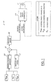
- the control system 10 shown in Figure 1 in accordance with the present invention is part of an electro-hydraulic power assist steering system which uses an electric motor 12 to drive a hydraulic pump, which in turn produces the system pressure used to move the steering rack. Movement of the steering rack is limited within a predetermined range by mechanical end stops, one at each end of the steering mechanism.
- the pump flow is continuously varied, preferably every millisecond, by control of the speed of the electric motor.
- This control technique provides the minimum amount of flow required to maintain good steering feel without wasting energy.
- This method of control provides a substantial improvement in efficiency over other electro-hydraulic and conventional power steering systems, since both generally provide excessive pump flow during most steering conditions.
- variable flow and an improved strategy permits the optimization of various steering modes, independent of one another, through appropriate control of the pump flow. Further, the steering system response can be widely reconfigured through unique and even driver specific calibrations of the control software, offering many new alternatives for customized steering feel.
- this algorithm uses vehicle speed (M V ), steering wheel relative position ( ⁇ SW ) and steering wheel turning rate ( ⁇ SW ) as the control inputs. It is notable that the system does not require a yaw sensor, a torque sensor or a separate steering wheel turning rate sensor, thus reducing the cost and complexity of the present invention relative to those that require this additional hardware.
- the system 10 establishes a base motor speed at block 17. Using the control inputs obtained from a steering wheel angle sensor and a vehicle speed sensor, the system determines what changes to make to the base motor speed at the driving condition modifier block 20. A desired motor speed signal is generated by summing the signals from blocks 17 and 20 at summation block 22. In this manner, a motor speed command is generated by the motor speed controller 24 in response to the desired motor speed.
- the end stop detection and desired motor speed limitation will be described in greater detail.
- the system must be able to detect impending or actual end stop contact. This can be done easily if an absolute center of the steering system is known, because the end stops are located approximately a constant distance from the center position of the steering. It is desirable, however, to avoid the cost of an absolute position sensor, therefore a method must be employed to rapidly find the center position of the steering system.
- ⁇ FCSWC find center based steering wheel center position
- the speed with which such a find center system acquires an accurate steering wheel center position, ⁇ FCSWC can be improved by incorporating a yaw sensor, however, even the fastest find center systems will not find a center position until the vehicle has traveled straight for some distance.
- the method of the present invention determines whether a find center steering wheel center position has been determined. If yes, the method advances to limit the desired motor speed if and when the steering rack becomes very close or actually engages one of the end stops, which will be described further below. If no, the method advances to block 32.
- the method determines if a steering wheel center position, ⁇ ESSWC , has been detected by detecting the end stops. If yes, the method advances to limit the desired motor speed if and when the steering rack becomes very close or actually engages one of the end stops. If no, the method advances to block 34.
- the method monitors steering system torque by monitoring an electrical current, I MOTOR , supplied to the drive motor, and determines if it exceeds an end stop electrical current threshold constant, I ES .
- I MOTOR an electrical current threshold constant
- the electrical current, I MOTOR must exceed the end stop electrical current threshold constant, I ES , for a predetermined period of time, T ES . Blocks 36, 38 and 40 effectively accomplishing this by restarting the process unless I MOTOR continuously exceeds I ES for a period of T ES .
- the method must determine which end stop, the right or the left, the steering system is against. This can be determined by evaluating the sign of a steering wheel signal, ⁇ SW , from the steering position sensor.
- ⁇ SW steering wheel signal
- the wheel When the vehicle is started, before the steering wheel is turned at all, it has a zero value. In order to hold the steering wheel against an end stop, the wheel must be turned a nominal amount in the direction of the end stop. This is due to forces in the suspension and steering system that force the steering system back toward center from an end stop position. So, even if the steering system were held against one of the end stops when the vehicle was shut off, the steering system would return a slight amount toward center. Therefore, upon restarting, the steering wheel must be turned toward the stop to again contact it. This provides enough signal to determine whether a right or left end stop has been detected and an appropriately signed steering wheel center position offset, ⁇ OFFSET , is calculated at block 44 or 46 in accordance with the known end stop position.
- the method proceeds to block 48, and calculates the end stop based steering wheel center position, ⁇ ESSWC , and an absolute steering wheel position, ⁇ SWA , relative thereto which will be used to determine if the desired motor speed needs to be limited at block 50.
- the method compares a magnitude of the current absolute steering wheel position, ⁇ SWA , determined by adjusting the steering wheel signal, ⁇ SW , in accordance with either the find center based steering wheel center position, ⁇ FCSWC , or the end stop based steering wheel center position, ⁇ ESSWC , against a steering travel limit, ⁇ ES .
- the steering travel limit may correspond directly to the actual physical end stop, or it may be set to a value slightly smaller than the angle of the physical end stop, about twenty degrees in the presently preferred embodiment. This would be desirable to provide further protection of the pump motor and greater flexibility in the control system. For instance, with this difference, it would be possible to reduce or limit the desired motor speed prior to attaining the actual end stops.
- the method reduces a desired motor speed to a predetermined end of travel motor speed until the steering wheel angle drops below the steering travel limit.
- the method When the system is against an end stop, the method will limit power consumption to a small level by reducing the desired motor speed to a predetermined end of travel motor speed at a limit block 52. The method then returns to block 50 such that the limit block 52 will continue to limit the desired motor speed until the steering wheel angle drops below the steering travel limit.
- the predetermined end of travel motor speed may be set to the base motor speed, or to a fixed or variable percentage of the desired motor speed.
Landscapes
- Engineering & Computer Science (AREA)
- Chemical & Material Sciences (AREA)
- Combustion & Propulsion (AREA)
- Transportation (AREA)
- Mechanical Engineering (AREA)
- Steering Control In Accordance With Driving Conditions (AREA)
- Power Steering Mechanism (AREA)
Claims (8)
- Un procédé pour limiter l'assistance hyraulique dans un système de direction assistée (10) comprenant un moteur électrique à vitesse variable (12) pour pomper un liquide hydraulique dans le système, la méthode étant caractérisée par les étapes de :surveiller l'angle du volant de direction du véhicule (SW) ;déterminer si ledit angle du volant de direction du véhicule (SW) dépasse une limite de course de direction (ES) ; etréduire une vitesse de moteur souhaitée à une vitesse de moteur de fin de course prédéterminée jusqu'à ce que ledit angle du volant de direction du véhicule (SW) devienne inférieur à ladite limite de course de direction (ES).
- Un procédé selon la revendication 1, dans lequel ladite limite de course de direction (ES) est sélectionnée de manière à ce que ledit angle du volant de direction (SW) excède ladite limite de course du volant de direction avant d'atteindre une position effective de fin de course.
- Un procédé selon la revendication 1, dans lequel ladite vitesse de moteur de fin de course prédéterminée est égale à une vitesse de moteur de base (17).
- Un procédé selon la revendication 1, dans lequel ladite étape de surveiller l'angle du volant de direction du véhicule comprend en outre les étapes de :surveiller (34 - 40) un courant électrique (IMOTOR) fourni audit moteur électrique à vitesse variable (12) et déterminer si ledit courant électrique excède un seuil de courant de fin de course (IES) pendant une période de temps prédéterminée (TES);surveiller (42) un signal de détection de volant de véhicule et déterminer (44, 46) si une fin de course à droite ou à gauche a été déterminée ; etcalculer une déviation de signal de direction de véhicule (OFFSET) pour son utilisation dans le calcul d'un angle de volant de direction de véhicule (SW) à partir dudit signal de détection de volant de véhicule.
- Un procédé selon la revendication 4, dans lequel l'étape de réduire la vitesse de moteur souhaitée à ladite vitesse de moteur de fin de course prédéterminée comprend la réduction de ladite vitesse de moteur jusqu'à ce que ledit signal de détection de volant de véhicule indique un montant prédéterminé de retour de direction.
- Un procédé selon la revendication 4, dans lequel l'étape de réduire la vitesse de moteur souhaitée à ladite vitesse de moteur de fin de course prédéterminée comprend la réduction de ladite vitesse de moteur jusqu'à ce qu'une magnitude dudit angle de volant de direction (SW) soit inférieure à ladite limite de course de direction (ES).
- Un procédé selon la revendication 6, dans lequel ladite limite de course de direction (ES) est sélectionnée de manière à ce que ledit angle de volant de direction (SW) excède ladite limite de course du volant de direction avant d'atteindre une position effective de fin de course.
- Un procédé selon l'une quelconque des revendications 5 à 7, dans lequel ladite vitesse de moteur de fin de course prédéterminée est égale à une vitesse de moteur de base (17).
Applications Claiming Priority (2)
| Application Number | Priority Date | Filing Date | Title |
|---|---|---|---|
| US09/088,791 US6073721A (en) | 1998-06-01 | 1998-06-01 | Method for limiting hydraulic assist in a power assist steering system |
| US88791 | 1998-06-01 |
Publications (3)
| Publication Number | Publication Date |
|---|---|
| EP0962377A2 EP0962377A2 (fr) | 1999-12-08 |
| EP0962377A3 EP0962377A3 (fr) | 2003-03-26 |
| EP0962377B1 true EP0962377B1 (fr) | 2005-11-02 |
Family
ID=22213501
Family Applications (1)
| Application Number | Title | Priority Date | Filing Date |
|---|---|---|---|
| EP99303921A Expired - Lifetime EP0962377B1 (fr) | 1998-06-01 | 1999-05-20 | Procédé pour limiter l'assistance hydraulique pour un système de direction assistée |
Country Status (4)
| Country | Link |
|---|---|
| US (1) | US6073721A (fr) |
| EP (1) | EP0962377B1 (fr) |
| JP (1) | JPH11348801A (fr) |
| DE (1) | DE69928044T2 (fr) |
Families Citing this family (20)
| Publication number | Priority date | Publication date | Assignee | Title |
|---|---|---|---|---|
| JP3673377B2 (ja) * | 1997-09-26 | 2005-07-20 | 光洋精工株式会社 | パワーステアリング装置 |
| JPH11334630A (ja) * | 1998-05-22 | 1999-12-07 | Koyo Seiko Co Ltd | パワーステアリング装置 |
| JP2001028748A (ja) * | 1999-07-12 | 2001-01-30 | Sony Corp | データ再生伝送装置及びデータ再生伝送方法 |
| DE10118739A1 (de) * | 2001-04-17 | 2002-11-14 | Trw Fahrwerksyst Gmbh & Co | Verfahren zum Steuern eines Servolenksystems |
| US6725963B2 (en) * | 2002-06-21 | 2004-04-27 | General Motors Corporation | Energy saving control system and method for reducing power consumption of an electro-hydraulic power steering system for a hybrid vehicle |
| US6988581B2 (en) * | 2002-11-14 | 2006-01-24 | Visteonglobal Technologies, Inc. | Fuel efficient power steering control system and method |
| DE10345293A1 (de) * | 2003-09-30 | 2005-05-04 | Bayerische Motoren Werke Ag | Betriebsverfahren für ein hilfskraftverstärktes Hydro-Lenksystem eines Kraftfahrzeugs |
| DE102006029587A1 (de) * | 2006-06-28 | 2008-01-03 | Jungheinrich Ag | Verfahren zur Einstellung eines Lenkbereichs bei einer elektrischen Lenkung für ein Flurförderzeug |
| US8190316B2 (en) * | 2006-10-06 | 2012-05-29 | Yamaha Hatsudoki Kabushiki Kaisha | Control apparatus for marine vessel propulsion system, and marine vessel running supporting system and marine vessel using the same |
| US8082078B2 (en) * | 2007-05-07 | 2011-12-20 | Nexteer (Beijing) Technology Co., Ltd. | Methods, systems, and computer program products for steering travel limit determination for electric power steering |
| JP2011148408A (ja) * | 2010-01-22 | 2011-08-04 | Fujitsu Ten Ltd | 電動油圧式パワーステアリング制御装置 |
| DE102010043679B4 (de) * | 2010-11-10 | 2024-02-01 | Knorr-Bremse Systeme für Nutzfahrzeuge GmbH | Betriebsverfahren für ein hydraulisches Servo-Lenksystem und hydraulisches Servo-Lenksystem |
| JP2013071559A (ja) * | 2011-09-27 | 2013-04-22 | Jtekt Corp | パワーステアリング装置 |
| FR2988065B1 (fr) * | 2012-03-15 | 2014-03-14 | Jtekt Europe Sas | Procede de controle de fin de course pour direction assistee electrique |
| JP6365866B2 (ja) * | 2013-11-22 | 2018-08-01 | 株式会社ジェイテクト | パワーステアリング装置 |
| DE102014118334B4 (de) | 2014-12-10 | 2024-05-16 | Dr. Ing. H.C. F. Porsche Aktiengesellschaft | Überlastschutz für eine hydraulische Lenkpumpe |
| EP3222497B1 (fr) * | 2014-12-25 | 2019-09-11 | NSK Ltd. | Dispositif de direction assistée électrique |
| CN110058617A (zh) * | 2018-01-18 | 2019-07-26 | 爱德利科技股份有限公司 | 电动液压动力辅助系统的控制方法 |
| US10800446B2 (en) | 2018-05-01 | 2020-10-13 | Ford Global Technologies, Llc | Methods and apparatus to modify steering assist of a hydraulic power steering system |
| EP3753808B1 (fr) * | 2019-06-17 | 2023-08-09 | Volvo Car Corporation | Butées dynamiques pour direction assistée électrique |
Family Cites Families (9)
| Publication number | Priority date | Publication date | Assignee | Title |
|---|---|---|---|---|
| US4153133A (en) * | 1977-11-25 | 1979-05-08 | General Motors Corporation | Steering travel limiter for power steering gear |
| FR2662987B1 (fr) * | 1990-06-08 | 1992-07-31 | Valeo Electronique | Dispositif de commande d'un dispositif d'assistance de direction pour vehicule. |
| JP2936162B2 (ja) * | 1992-02-14 | 1999-08-23 | 本田技研工業株式会社 | 車両の操安制御装置 |
| DE4419049C2 (de) * | 1993-06-01 | 2002-10-31 | Mitsubishi Motors Corp | Steuersystem und -verfahren für eine Servolenkvorrichtung |
| DE4335390B4 (de) * | 1993-10-16 | 2007-04-12 | Trw Fahrwerksysteme Gmbh & Co Kg | Servolenkvorrichtung |
| JP3525269B2 (ja) * | 1995-03-09 | 2004-05-10 | 光洋精工株式会社 | パワーステアリング装置 |
| JP3506810B2 (ja) * | 1995-06-19 | 2004-03-15 | ユニシア ジェーケーシー ステアリングシステム株式会社 | 電動ポンプ式動力舵取装置 |
| JPH1081247A (ja) * | 1996-09-09 | 1998-03-31 | Honda Motor Co Ltd | カウンタステア判定装置 |
| US5919241A (en) * | 1996-12-13 | 1999-07-06 | General Motors Corporation | Vehicle having electric power steering with active damping |
-
1998
- 1998-06-01 US US09/088,791 patent/US6073721A/en not_active Expired - Fee Related
-
1999
- 1999-05-20 DE DE69928044T patent/DE69928044T2/de not_active Expired - Fee Related
- 1999-05-20 EP EP99303921A patent/EP0962377B1/fr not_active Expired - Lifetime
- 1999-05-25 JP JP11145094A patent/JPH11348801A/ja active Pending
Also Published As
| Publication number | Publication date |
|---|---|
| EP0962377A3 (fr) | 2003-03-26 |
| DE69928044T2 (de) | 2006-07-06 |
| US6073721A (en) | 2000-06-13 |
| JPH11348801A (ja) | 1999-12-21 |
| DE69928044D1 (de) | 2005-12-08 |
| EP0962377A2 (fr) | 1999-12-08 |
Similar Documents
| Publication | Publication Date | Title |
|---|---|---|
| EP0962377B1 (fr) | Procédé pour limiter l'assistance hydraulique pour un système de direction assistée | |
| EP0962378B1 (fr) | Méthode de commande pour direction assistée électrohydraulique | |
| US4392540A (en) | Power steering device for a vehicle | |
| US6542800B2 (en) | Lane following vehicle control | |
| US7596441B2 (en) | Power steering device | |
| US6782968B2 (en) | Automatic steering apparatus for vehicle and control method of same | |
| JP4509238B2 (ja) | 車両ブレーキ装置の制御方法および装置 | |
| KR100749651B1 (ko) | 차량의 선회 거동 제어 장치 | |
| US4733878A (en) | Four-wheel steering system for vehicle | |
| US6101435A (en) | Method for compensating a power assist steering system control signal | |
| US8714298B2 (en) | Pump apparatus | |
| KR100316911B1 (ko) | 차량의 파워 스티어링 | |
| KR100225963B1 (ko) | 엔진지게차의 조향시스템 제어방법 및 그 장치 | |
| EP3981669B1 (fr) | Procédé de commande d'un système d'assistance de direction d'un véhicule | |
| JPH11255134A (ja) | 電動油圧パワーステアリング装置 | |
| JP3178214B2 (ja) | 車両用自動操舵装置 | |
| KR102882264B1 (ko) | 전동식 조향장치(mdps)의 토크신호 제어방법 | |
| JP3500220B2 (ja) | パワーステアリング装置 | |
| KR100247338B1 (ko) | 차량용 조향장치 | |
| JPH03112776A (ja) | 動力舵取装置の制御装置 | |
| JPH02127168A (ja) | 車両用動力操舵装置の制御装置 | |
| KR19990075735A (ko) | 차량의 파워 스티어링 제어장치 및 방법 | |
| JPH01288661A (ja) | 産業車両におけるスリップ防止装置 | |
| KR20110062407A (ko) | 전동식 유압 파워 스티어링 시스템의 모터제어방법 | |
| JPH04185559A (ja) | 路面摩擦係数検出方法およびそれに用いる装置 |
Legal Events
| Date | Code | Title | Description |
|---|---|---|---|
| PUAI | Public reference made under article 153(3) epc to a published international application that has entered the european phase |
Free format text: ORIGINAL CODE: 0009012 |
|
| AK | Designated contracting states |
Kind code of ref document: A2 Designated state(s): AT BE CH CY DE DK ES FI FR GB GR IE IT LI LU MC NL PT SE |
|
| AX | Request for extension of the european patent |
Free format text: AL;LT;LV;MK;RO;SI |
|
| PUAL | Search report despatched |
Free format text: ORIGINAL CODE: 0009013 |
|
| AK | Designated contracting states |
Kind code of ref document: A3 Designated state(s): AT BE CH CY DE DK ES FI FR GB GR IE IT LI LU MC NL PT SE Designated state(s): AT BE CH CY DE DK ES FI FR GB GR IE IT LI LU MC NL PT SE |
|
| AX | Request for extension of the european patent |
Extension state: AL LT LV MK RO SI |
|
| 17P | Request for examination filed |
Effective date: 20030828 |
|
| AKX | Designation fees paid |
Designated state(s): DE FR GB |
|
| 17Q | First examination report despatched |
Effective date: 20041221 |
|
| GRAP | Despatch of communication of intention to grant a patent |
Free format text: ORIGINAL CODE: EPIDOSNIGR1 |
|
| GRAS | Grant fee paid |
Free format text: ORIGINAL CODE: EPIDOSNIGR3 |
|
| GRAA | (expected) grant |
Free format text: ORIGINAL CODE: 0009210 |
|
| AK | Designated contracting states |
Kind code of ref document: B1 Designated state(s): DE FR GB |
|
| REG | Reference to a national code |
Ref country code: GB Ref legal event code: FG4D |
|
| REG | Reference to a national code |
Ref country code: GB Ref legal event code: 732E |
|
| REF | Corresponds to: |
Ref document number: 69928044 Country of ref document: DE Date of ref document: 20051208 Kind code of ref document: P |
|
| PG25 | Lapsed in a contracting state [announced via postgrant information from national office to epo] |
Ref country code: GB Free format text: LAPSE BECAUSE OF NON-PAYMENT OF DUE FEES Effective date: 20060520 |
|
| PLBE | No opposition filed within time limit |
Free format text: ORIGINAL CODE: 0009261 |
|
| STAA | Information on the status of an ep patent application or granted ep patent |
Free format text: STATUS: NO OPPOSITION FILED WITHIN TIME LIMIT |
|
| 26N | No opposition filed |
Effective date: 20060803 |
|
| PG25 | Lapsed in a contracting state [announced via postgrant information from national office to epo] |
Ref country code: DE Free format text: LAPSE BECAUSE OF NON-PAYMENT OF DUE FEES Effective date: 20061201 |
|
| EN | Fr: translation not filed | ||
| PG25 | Lapsed in a contracting state [announced via postgrant information from national office to epo] |
Ref country code: FR Free format text: LAPSE BECAUSE OF FAILURE TO SUBMIT A TRANSLATION OF THE DESCRIPTION OR TO PAY THE FEE WITHIN THE PRESCRIBED TIME-LIMIT Effective date: 20061222 |
|
| GBPC | Gb: european patent ceased through non-payment of renewal fee |
Effective date: 20060520 |
|
| PG25 | Lapsed in a contracting state [announced via postgrant information from national office to epo] |
Ref country code: FR Free format text: LAPSE BECAUSE OF FAILURE TO SUBMIT A TRANSLATION OF THE DESCRIPTION OR TO PAY THE FEE WITHIN THE PRESCRIBED TIME-LIMIT Effective date: 20051102 |