EP0962324A1 - Tintenstrahldruckverfahren und Tintenstrahldruckgerät - Google Patents
Tintenstrahldruckverfahren und Tintenstrahldruckgerät Download PDFInfo
- Publication number
- EP0962324A1 EP0962324A1 EP99303984A EP99303984A EP0962324A1 EP 0962324 A1 EP0962324 A1 EP 0962324A1 EP 99303984 A EP99303984 A EP 99303984A EP 99303984 A EP99303984 A EP 99303984A EP 0962324 A1 EP0962324 A1 EP 0962324A1
- Authority
- EP
- European Patent Office
- Prior art keywords
- ink
- black
- colored
- low concentration
- cyan
- Prior art date
- Legal status (The legal status is an assumption and is not a legal conclusion. Google has not performed a legal analysis and makes no representation as to the accuracy of the status listed.)
- Granted
Links
Images


Classifications
-
- C—CHEMISTRY; METALLURGY
- C09—DYES; PAINTS; POLISHES; NATURAL RESINS; ADHESIVES; COMPOSITIONS NOT OTHERWISE PROVIDED FOR; APPLICATIONS OF MATERIALS NOT OTHERWISE PROVIDED FOR
- C09D—COATING COMPOSITIONS, e.g. PAINTS, VARNISHES OR LACQUERS; FILLING PASTES; CHEMICAL PAINT OR INK REMOVERS; INKS; CORRECTING FLUIDS; WOODSTAINS; PASTES OR SOLIDS FOR COLOURING OR PRINTING; USE OF MATERIALS THEREFOR
- C09D11/00—Inks
- C09D11/30—Inkjet printing inks
- C09D11/40—Ink-sets specially adapted for multi-colour inkjet printing
-
- B—PERFORMING OPERATIONS; TRANSPORTING
- B41—PRINTING; LINING MACHINES; TYPEWRITERS; STAMPS
- B41J—TYPEWRITERS; SELECTIVE PRINTING MECHANISMS, i.e. MECHANISMS PRINTING OTHERWISE THAN FROM A FORME; CORRECTION OF TYPOGRAPHICAL ERRORS
- B41J2/00—Typewriters or selective printing mechanisms characterised by the printing or marking process for which they are designed
- B41J2/005—Typewriters or selective printing mechanisms characterised by the printing or marking process for which they are designed characterised by bringing liquid or particles selectively into contact with a printing material
- B41J2/01—Ink jet
- B41J2/21—Ink jet for multi-colour printing
- B41J2/2107—Ink jet for multi-colour printing characterised by the ink properties
Definitions
- the invention relates to an ink printing method and an ink-jet printing apparatus, and specifically to an ink-printing method and an ink-jet printing apparatus for performing printing by using a processing liquid which make a coloring material in an ink insoluble.
- OD optical density
- an OD of a dot formed with the ink on the printing medium depends is an amount of a coloring material of the ink which does not penetrate into the printing medium but remains on a surface thereof. From this point of view, it is well known to increase an amount per se of ink ejected by a print head. As an easier method, for example, it is widely performed to scan the print head plural times for ejecting the ink plural times on a same point to increase an ink quantity to be given onto the printing medium.
- the assignee of this application provides a printing apparatus and a printing method disclosed in Japanese Patent Application Laying-open No. 8-281930 (281930/96).
- a black ink is ejected and the processing liquid is also ejected in a predetermined pattern of pixels.
- this processing liquid also functions as cyan ink which is made cationic to be oppositely polarized to anionic black ink.
- the increase in the optical density is aimed at while preventing color tone from deviating by performing printing in other colors in a pattern simultaneously.
- a print head provided for the processing liquid is not required. Also, it is possible with a simple configuration to achieve the effects such as an improvement in water resistance and prevention from feathering and bleeding by use of the processing liquid, in addition to improvement of print quality due to increasing in the density.
- a similar art disclosed in a gazette of EP A 831135 with respect to European Patent Application is also known.
- the gazette discloses that a light color ink, which is low concentration ink of magenta or cyan, is applied to the printing medium in an overlaying manner with the black ink and the light color ink is made have property that insolubilizes the black ink.
- ejection position may become uneven among multiple-time scanning of the print head for ejecting ink multiple times on a same position, due to uneven motions of a carriage.
- the above-mentioned deviation of ink dots upon overlaying them may become uneven among multiple-time scanning of the print head for ejecting ink multiple times on a same position, due to uneven motions of a carriage.
- this full line type print head is of a long-size for arranging relatively large amount of ejection orifices which are arranged in extent corresponding to a width of printing paper fed for printing. Therefore, the deviation may sometimes extend to that equivalent to about a few pixel which is arranged in 600 dpi.
- the above deviation may be caused also when there are variations in the direction of ejected ink between the print heads.
- the ink or the ink equivalent to the processing liquids from that ejection orifices are not ejected at the position to be originally targeted on.
- the deviation is caused in overlaying them.
- An aspect of the present invention is to provide an ink print method and an ink-jet printing apparatus which can achieve an improvement in print quality beginning with an increase in density of printed image while permitting the deviation even if it is caused in overlaying of ink dots owing to the above-described various factors.
- the applicant of the present invention has achieved this invention by paying attention to and examining a relation between a mutual deviation value between plural ink dots and a relative density in a range in which this deviation does not have a significant influence on the print quality.
- Another aspect of the present invention is to provide an ink print method and an ink-jet printing apparatus in which, in a case of forming an image of a black , a low concentration colored ink having an opposite polarity to that of a black ink is added thereto in an overlaying manner, the deviation can be made visually unrecognized for the low concentration of the colored ink even if the overlaid condition of inks is not within a predetermined range, and in addition to an increase in density due to insolublization of the black ink, the increase in the density of the black image within a range in which no change is recognized in the hue.
- an ink printing method comprising the steps of:
- an ink printing method comprising the steps of:
- an ink printing method comprising the steps of:
- an ink-jet printing apparatus for performing printing by means of ink ejection parts respectively ejecting a black ink, and a low concentration colored ink which has a lower concentration than a colored ink with higher lightness than that of the black ink, has a same color as that of the colored ink and has a polarity different from the black ink,
- an ink-jet printing apparatus for performing printing by means of ink ejection parts respectively ejecting a black ink, one of or a plurality of colored inks having higher lightness than a black ink and a low concentration colored ink which has a lower concentration than the colored ink, has a same color as that of the colored ink and has a polarity different from that of the a black ink
- an ink-jet printing apparatus for performing printing by means of ink ejection parts respectively ejecting a plurality of colored inks different from the a black ink and having higher lightness than that of the black ink, and a low concentration colored ink having a lower concentration than that of the colored ink and a different polarity from that of the colored ink,
- a low concentration colored ink which is employed together with a black ink and one or a plurality of colored inks having higher lightness than the black ink in a printing apparatus, has lower concentration than the colored ink and has a same color as the colored ink,
- an ink set comprising:
- an ink set comprising:
- an ink set comprising:
- an ink manufacturing method of manufacturing a low concentration colored ink which is employed together with a black ink and one or a plurality of colored inks having higher lightness than the black ink in a printing apparatus, has lower concentration than the colored ink and has a same color as the colored ink has, the method comprising the steps of:
- a rubbing resistance improving method used when performing printing with a black ink and a low concentration colored ink having lower concentration than a colored ink which has higher lightness than the black ink, having a same color as the colored ink and having a function making the black ink insoluble, the method comprising the steps of:
- an ink ejection data generation method comprising the steps of:
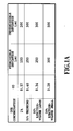
- Figs. lA and 1B are drawings explaining a relation between ODs realized by a cyan ink dot and permissible deviation amount of overlaid cyan ink dot and black ink dot from each other.
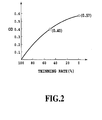
- Fig. 2 is a graph showing a relation between a thinning rate in cyan ink dot pattern and OD realized by the pattern.
- Figs. 3A and 3B are drawings schematically showing respective deviations of cyan ink dots in the case that the cyan ink of respective 100 % duty (the thinning rate is 0) and 50 % of thinning rate are overlaid on the black ink.
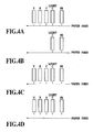
- Figs. 4A-4D are drawings showing combinations of inks used for printers related to embodiments of the present invention.
- Fig. 5 is a side view showing a schematic configuration of a printing apparatus related to one embodiment of the present invention.
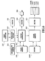
- Fig. 6 is a block diagram showing a control configuration of the printing apparatus shown in Fig. 5.
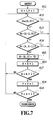
- Fig. 7 is a flowchart showing generating procedure performed in the control configuration shown in fig. 6 for generating ejection data of light cyan ink in relation to printing black image or the like.
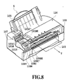
- Fig. 8 is a perspective view showing a printing apparatus related to another embodiment of the present invention.
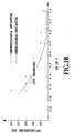
- Fig. 9 is a graph showing a relation between a percentage content of acethylenol and Ka value indicating a penetration speed.
- Figs. 10A and 10B are characteristic charts respectively showing relations between penetration quantity of ink and elapse of time.
- Figs. 11A-11C are schematic drawings respectively showing print head configurations of printing apparatuses related further to other embodiments of the present invention.
- Figs. 12A and 12B are schematic drawings showing head configurations of a printing apparatuses related further to other embodiments of the present invention.
- a low concentration light cyan (hereafter also simply called “light C”) is applied on a part or whole part of pixels on which the black ink is applied in an overlaying manner.
- the Bk ink has a polarity of anionic
- the light C ink is made to have a reverse polarity to be cationic, and thus, the Bk ink and light C ink are mixed on a printing medium to cause a coloring material in the Bk ink to be insoluble or coagulated.
- Figs. 1A and 1B are a chart and a graph respectively explaining permissible deviation values which are hard to be visually recognized and not permissible deviation values which cause degradation of print quality with respect to respect ODs of cyan ink.
- C inks which are used as that of respective 1% and 0.5% concentrations of dye as a coloring material.
- the C ink of 1% dye concentration has about 1/3 times dye concentration as that of C ink which is generally used for printing, and therefor, the 0.5% dye concentration has about 1/6 times dye concentration as that of the general use C ink.
- the distinction between the permissible deviation value and not permissible deviation value has been investigated also in the case that quantity of the C ink applied to Bk ink is thinned at 50%.
- the distinction of those deviation values has been examined concerning two different ejection amounts. It should be noted that the eject amounts are made differentiated from each other by means of a method which has a case of increasing the ejection amount by using what is called a double pulse and a case using a normal single pulse.
- the double pulse method has been proposed by the assignee of the present application.
- the ODs for each of the above dye concentration become 0.57, 0.40, 0.34, and 0.28 respectively, as shown in Fig. lA.
- the measurements of these ODs have been carried out as follows. Forming of dots is performed on a predetermined size of area on the printing medium with each ink of the above-mentioned dye concentration so that an area factor becomes 100 % with performing what is called solid printing (100 % duty) or so that dots are formed in thinning pattern of 50%. Then, the ODs of the formed dot patterns are measured by using a Macbeth density meter.
- Fig. 2 is a graph showing an example of the relation between a thinning rate in forming dots and an OD measured thereto. It is apparent from the graph that a value of the OD is not reduced by 50% for 50% thinning rate as it varies from 0.57 to 0.4.
- Fig. 1A is a graph obtained by plotting a relation between the ODs and the deviation values.
- the solid printing is performed with C ink in a condition of deviating forming positions with various deviation values, onto the solid printing with Bk ink ( in this case, an OD value of 0.57 is obtained from the solid printing per se with , for example, 1% C ink as aforementioned, and the same with others), and as shown in Fig. 3B, C ink is applied with various deviation values and 50% thinning rate, onto the solid printing with Bk ink (in this case, an OD value of 0.4 is obtained from a pattern per se with C ink as aforementioned). Then, evaluation is performed in both cases whether or not the deviations are visually noticeable.
- the relation shown in Fig. 1B is one in the case where the OD of black pixel formed with Bk and C inks is that within 1.4-1.6.
- the gradient of a curve showing the relation becomes smaller in a range having smaller OD than 0.6 of C ink dot, bordered thereon, and the permissible deviation value becomes slightly smaller.
- a shape of the curve is almost the same as that shown in Fig. 1B in a point that the permissible deviation value becomes steeply larger in the range of OD of C ink dot at 0.6 and smaller.
- an OD of C ink dot upon performing printing with an ink-jet printing apparatus can be determined, for example, as follows.
- the optical density of a solid picture printed with light C ink which has low dye concentration, about 1/2 times as the optical density of a solid picture printed with usually used C ink to form a halftone image suitably.
- concentration of the C ink is made too light, it becomes difficult to design the halftone image.
- the OD of C ink dot is 0.2 or larger in any case.
- the OD achieved with C ink may practically be in a range of 0.2 - 0.6 including the range of 0.4 and larger.
- Such the OD range of 0.2- 0.6 of C ink dot is achievable by using a relatively light ink of 5% or 1% dye concentration as is apparent, for example, from Fig. 1A.
- this concentration of 0.5% and 1% are 1/6 and 1/3 times as that of dye concentration of normally used C ink, respectively.
- such an absolutely low concentration of ink is called "light ink”.
- one ink of a relatively lower concentration and used for overlaying with Bk ink is also called "light ink”.
- Figs. 4A-4D are drawings schematically showing arrangements of print heads on such ink-jet printers as mentioned above, respectively. These figures illustrate full line type print heads from the side view point with respect to the direction of paper feeding, and a combination of the print heads shown in each figure is not limited to such full line type. It is apparent that the combinations of serial type print heads arranged on the carriage as shown in each figure may be allowed.
- the print heads arranged from the upstream side to the downstream side in the direction of paper feeding eject Bk ink, light C ink, C ink, magenta (hereafter, simply described “M”) ink, and yellow (hereafter simply described “Y”) ink, respectively.
- M magenta
- Y yellow
- the concentration of a coloring material of a dye or a pigment in light C-ink can be made in the range of 0.3%-1.5%.
- the coloring material concentration of this light C ink corresponds to 1/2.5-1/6 times as that of the coloring material concentration of C ink used in the printer of this embodiment.
- light C ink has cationic polarity
- Bk ink and other Y, M, C inks have oppositely anionic polarity, and this make each color material insoluble or coagulated when Bk ink is overlaid with the light C ink.
- predetermined effects such as an improvement in density of Bk ink dots, a reduction in feathering, and an improvement in water resistance, etc. can be achieved.
- the light C ink and the C ink are applied together with each other in a predetermined reproducing density area for reducing granular feeling especially in a low density part and for achieving smooth changes in gradation.
- a predetermined density distribution table is used to convert input density data of cyan, in a range of relatively small input density data of cyan, into density data of the light C ink according to the value of the input data, and to convert them, in a range of large input data, into individual density data of the light C ink and the C ink in a distributing manner. In the latter conversion, the larger the input density data value is, the more the distribution ratio for the C ink is increased.
- the OD achieved by solid printing with light C ink is preferred to be 1/2 times as that of the OD by the C ink.
- a ratio of a color material concentration of the light C ink to that of the C ink is 1/2.5-1/6 and the OD in this relation also can be achieved by thinning of dots, as described above.
- Fig. 4B shows an arrangement of print heads for performing monochrome printing in black, and a case of employing a combination of respective print heads for Bk ink and light C ink.
- the Bk ink is anionic and the light C ink to be applied on the Bk ink is cationic, having an opposite polarity to that of the Bk ink.
- low concentration blue (also simply described "B") ink is used instead of the light C ink.
- B low concentration blue
- the use of blue ink which is similar-colored ink to C ink can achieve substantially same effect as the case of overlaying the light C ink on Bk ink.
- this light B ink is used together with C ink by using the specified density distribution table as described above.
- the above-stated blue ink means ink containing coloring materials of blue and cyan which are the coloring material for the B ink and the C ink, respectively.
- Fig. 4D shows a configuration wherein B ink, red (hereafter simply described “R”) ink and green (hereafter simply described “G”) ink are used instead of C, M, and Y inks in response to the use of the light B ink. Also in this configuration, it remains unchanged that the light B ink is ejected and overlaid on Bk ink when black characters, etc. are printed.
- R red
- G green
- the light C ink or the light B ink similar to the light C ink are used for the inks to be overlaid on Bk ink.
- kinds of overlaying light inks are not to be restricted to them.
- the use of light M ink or light Y ink also makes it possible to carry out printing without recognition of dot deviation when an OD realized by their color material concentrations is appropriately determined.
- ink dots of C or B ink have relatively low lightness and have rather close hues to that of Bk ink, therefore, it is desirable to use light C ink or light B ink for decreasing recognition of the dot deviation.
- cationic dyes can be used, for example, for the light C ink or the light B ink, while an anionic dye can be used for each of Bk ink as well as Y, M, C inks or G, R, B inks.
- an anionic pigment or a mixture of this anionic pigment and an anionic dye as the coloring material for Bk ink.
- the coloring material for Bk ink may be a mixture of an anionic pigment without dispersing agent and a anionic dye.
- a light ink to be overlaid on Bk ink is not limited to be the cationic ink.
- the prescribed effect of the present invention can be achieved even if this light ink is made to be anionic and at least Bk ink in the other inks is made to be cationic.
- an ejection order of the anionic and the cationic inks is not limited to one way for obtaining the above-described effect of the present invention.
- the light C of cationic is ejected after the Bk ink to be made insoluble is ejected so that the light C ink is overlaid on the Bk ink.
- the coloring material on the printing medium is covered with the cationic dye to improve rub resistance against rubbing a character, an image or the like printed on the printing medium with a line-marker, for example.
- Fig. 5 is a side view showing an outline of a configuration of a full line type printing apparatus related to the first example.
- This printing apparatus 1 adopts an ink-jet printing system for carrying out printing by ejecting inks from plural full line type print heads arranged at predetermined positions along a feeding direction (the direction of the arrow A in the figure) of a printing medium as a printing medium.
- the Apparatus operates with control by a control circuit shown in Fig. 6 as will be described later.
- Each print head 101Bk, 101C', 101C, 101M, and 101Y of a head group 101g is provided with approximately 7200 pieces of ink ejection orifices with a density of 600 dpi arranged in the width direction of printing paper (direction vertical to the plane of the figure). Each head is capable of printing on an A3-size printing paper.
- the printing paper 103 is fed in the direction of the arrow A by the rotation of a pair of resist-rollers 114 driven by a transport motor, and is guided by a pair of guide plates 115 and the leading edge is registered before transported by the handler belt 11.
- the endless handler belt 111 is held by two pieces of rollers 112, 113, and vertical deviation of its upper side part is restricted by a platen 104.
- the printing paper 103 is transported by means of rotary driving of the roller 113. Moreover, the printing paper 103 is absorbed with an electrostatic force on the handler belt 111.
- the roller 113 is rotatably driven by a driving source of unshown motor, etc. so as to transport the printing paper 103 in the direction of the arrow A.
- the printing paper 103 on which printing has been carried out by the printing head group 101g during the transportation on the handler belt 111, is discharged onto a tray 116.
- the head 101Bk1 ejecting Bk ink described in the above mode of the embodiment the head 101C' ejecting cationic light C ink with an opposite polarity to the Bk ink, and the heads 101M, 101Y ejecting M-ink and Y-ink respectively are arranged in the transport direction A of the printing paper 103 as shown in the figure. And, it becomes possible to print characters in black and pictures in color by ejecting each color ink from each print head.
- the light C ink is ejected to be overlaid on the Bk ink as described in the aforementioned embodiment.
- Fig. 6 is a block diagram showing a control configuration of the full line type printing apparatus 1 illustrated in Fig. 5.
- a system controller 201 comprises firstly a microprocessor, ROM storing a control program executed in this device, RAM used for a work area when the microprocessor operates processing, etc., and executes the control of the whole device.
- a motor 204 is controlled in the driving via a driver 202, and drives the roller 113 shown in Fig. 5 to transport the printing paper.
- a host computer 206 transfers printing information to the printer 1 of this example, and controls its printing operation.
- a receiving buffer 207 temporarily stores data from the host computer 206, and keeps the data accumulated until a system controller 201 starts reading the data.
- a frame memory 208 is a memory for developing the printing data into image data, and has a necessary size of memory for printing. This example is described, assuming that the frame memory 208 has a memory capacity enough to store information for one sheet of printing paper, however, the present invention is not to be restricted by a capacity of the frame memory.
- a buffer 209P temporarily stores the printing data, and has a memory capacity corresponding to the number of the print heads and the number of the eject orifices of each head.
- a print control part 210 is one for properly controlling the drive of the print heads according to the instruction from the system controller 201, and controls a drive frequency, the number of print data, etc., and further, creates data for ejecting the light C ink to be overlaid on the Bk ink based on the ejecting data of the Bk ink, to add it to the data of the light C ink as a picture.
- a driver 211 is one for eject-driving of the print heads 101Bk, 101C', 101C, 101M, 101Y for letting them eject each ink, and controlled by a signal from the print control part 210.
- the print data are transferred from the host computer 206 to the receiving buffer 207 to be temporarily stored.
- the stored print data are read out by the system controller 201 and developed into the buffer 209P.
- the print control part 210 creates data for ejecting the light C ink and stores them in the buffer 209P, based on the Bk ink data of the picture data developed into the buffer 209P.
- OR data of the light C ink data at the time of forming these black dots and the light C ink data at the time of forming cyan dots used together with the C ink or used alone are to be stored in the buffer 209P.
- the print control part controls the ejecting operations of each print head.
- Fig. 7 is a flowchart showing a ejection data generating procedure for the light cyan (C') ink, mentioned above.
- the ejection data of the light C ink is generated based on the ejection data of Bk ink stored in the buffer 209P shown in Fig. 6. More specifically, bitmap data of an amount equivalent to one page, which data is obtained by making image data binary to which a predetermined image processing has been done, is stored for each C, light C, M, Y and Bk color.
- the procedure thins the ejection data of Bk ink at rate of 50% to generate the ejection data of the light C ink to be overlaid on the Bk ink, as thinned data.
- a concentration of dye in the light C ink is 1% in this embodiment and is determined so that OD measured for a pattern becomes 0.4 when the pattern is printed by using the light C ink of the above-mentioned concentration at thinning rate of 50%. Moreover, the procedure of this embodiment generates the ejection data of one page for suitably responding to a printing speed of the full line heads.
- parameters X, Y representing respective pixel locations is initialized (step S11).
- the parameter X shows the pixel location in a direction corresponding to an arrangement direction of ejection orifices on the print head and the parameter Y shows the pixel location in a direction corresponding to a transporting direction of the printing medium.
- the data P C .(X-I, Y) is ejection data of a pixel sifted in a X-direction by one pixel and is determined immediately before.
- ejection data P C' (X, Y-1) of the light C ink is "1" (ejection) or "0" (not ejection).
- the ejection data P C' (X, Y-1) is corresponding ejection data of pixel located sifted by one line of pixels to the subject pixel.
- the ejection data P C' (X, Y) of the subject pixel is determined to be "1", that is, to become data representing "ejection".
- the processing mentioned above is performed with respect to number "m” of pixels in one line and number "n” of lines in one page (step S16-step S19) and the processing is terminated.
- the light C inks are ejected to pixels defining a character, an image and the like printed with black ink, in what is called checker pattern so that printing of the light C ink is performed at substantially 50% of thinning rate to a black image.
- the processing shown in Fig. 7 as well as an image processing and conversion to binary data are performed in the printer in the above-mentioned embodiments. However, it is not limited to this structure.
- the above-stated processing may be performed by means of a printer driver in the host computer 206.
- the light C ink and the Bk ink are applied in an overlaying manner.
- the light C ink may be applied on the Bk ink.
- ink having a property of low penetration speed to the printing medium (hereafter simply called “hard penetration ink” in this example) is used for the black ink ejected from the head 101 Bk.
- ink having a property of high penetration speed to the printing medium (hereafter called “high penetration ink” in this example) is used for each of the light C, the cyan, magenta, and yellow inks ejected from the heads 101C', 101C, 101M, and 101Y respectively.
- the ink drops are mostly absorbed in the rugged part on the surface (a rough part on the printing paper surface), and does not penetrate into the printing paper yet.
- This period of time is tw (a wet time), and an absorbed volume into the rugged part in this period is Vr.
- tw a wet time
- Vr an absorbed volume into the rugged part in this period
- Fig. 9 is a curve showing a value of the proportional coefficient Ka to a content rate of ethylene oxide-2, 4, 7, 9-tetramethyl -5- decyne - 4,7- diol (hereafter called "acethylenol” : a product name manufactured by "Kawaken Fine Chemical”).
- Ka have been measured by using a liquid dynamic penetrability test equipment S (manufactured by "Toyo Seiki Seisakusho") according to Bristow Method.
- PB paper of Canon Inc. the assignee of the present invention, was used as printing paper.
- This printing paper is usable for a copying machine and Laser beam printer adopting an electrophography system as well as for a printer adopting an ink-jet printing system.
- PPC paper which is paper for electrophotography manufactured by Canon Inc.
- the curve shows that Ka value (vertical axis) increases with increasing content rate (horizontal axis) of the acethylenol, and that the proportional coefficient Ka is determined by the content rate of acethylenol. Therefore, the penetration speed of ink is to be substantially determined by the content rate of the acethylenol.
- the line segments intersecting the curve in parallel with the vertical axis show deviation ranges of the measurement result.
- Figs. 10A and 10B are characteristic curves showing relations between a penetration volume of ink and an elapse of time and these are the results of the experiments carried out by using the printing paper of 64g/m 2 , 80 ⁇ m thickness, and about 50% of voids.
- Fig. 10A the horizontal axis is graduated in units of 1/2 power of an elapse of time t; (msec 1/2 ), and in Fig. 10B, the horizontal axis is graduated in units of an elapse of time t; (msec).
- the vertical axes are graduated in penetration volumes( ⁇ m), and the curves are those when the content rates of the acethylenol are 0%, 0.35%, and 1% respectively.
- the graphs show that there is such a tendency as the more the content volume of the acethylenol becomes, the shorter the wet time tw is, and even before the time of tw, the higher the content rate of the acethylenol is, the higher the penetrability is.
- the penetrability of the ink is low and has a characteristic of an hard penetration ink which will be specified later.
- an ink mixed with 0.35% the acethylenol has an intermediate characteristic of semi-penetrability between the two cases.
- the Ka values listed in Table 1 were measured by using a liquid dynamic penetrability test equipment S (manufactured by Toyo Seiki Seisakusho) according to Bristow method.
- PB paper of Canon Inc. the Applicant of the present invention, was used as printing paper.
- CMC critical micelle concentration
- the critical micelle concentration shown in the figure is made to correspond to the aforementioned Table 1, it can be seen that for example, the "high penetration ink " specified in Table 1 contains the the acethylenol at a higher rate than the critical micelle concentration (CMC) of the acethylenol in water.
- CMC critical micelle concentration
- compositions of the light C ink and other inks used for this example are as follows.
- the light C ink and other inks are made by adding the respective solvents to the respect coloring materials.
- percentages (parts) of each component are expressed in parts by weight.
- [Light cyan (C') ink] Cationic dye (Basic dye) BB100 1 part. Glycerin 7 parts. Diethyl glycol 5 parts. Acethylenol EH 1 parts. (manufactured by "Kawaken Fine Chemical") Polyallylamine 4 parts. Acetic acid 4 parts Benzylidine dichloride 0.5 parts. Triethylene glycol-monobutylether 3 parts. Water remainder [Yellow (Y) ink] C. I.
- Pigment dispersion liquid 25 parts.
- Hood black 2 2 parts.
- Acethylenol EH 0.1 parts. Water remainder
- the above black is a mixture of a pigment without dispersing agent and a dye used as a color material, and its pigment dispersion liquid is as the following:
- anthranilic acid is added to a solution of 5g concentrated hydrochloric acid dissolved in 5.3g water at 5°C. This solution is always kept at 10°C or lower by stirring it in an ice-bath, and another solution of 1.78g sodium nitrite added into 8.7g water of 5°C was added to the former solution. Further, after stirring it for 15 minutes, 20g carbon black having 320 m 2 /g surface area and 120 ml/100g oil absorption quantity was added in a mixed state.
- a pigment dispersion liquid 3 is obtained, in which self-dispersion type carbon black bonded to a hydrophilic radical via a phenyl radical and anionically electrified is dispersed on the surface as shown by the formula below.
- each of the pigment and dye for black ink is arranged as additional ink, and each of the C' (the light C) and the C, M, and Y inks is arranged as high penetration ink.
- the color material concentration of light C ink is 1% equivalent to 1/3 times as that of the color material concentration of C ink, and therefore, the OD obtained from solid printing with this the light C ink becomes 0.57 as shown in the aforementioned embodiment.
- ejecting data of the light C ink are made to 50% thinned-out data compared with those of the Bk ink, and the OD of the pattern is made to 0.4.
- the positional deviation between the Bk ink and the light C ink in ink ejecting becomes about 200 ⁇ m, it is possible to make the positional deviation in ink ejecting inconspicuous with the device in this example, and also obtain a predetermined density of the Bk ink dots.
- a positional deviation of 100 ⁇ m is not a problem even if the data for light C are not thinned out, and also OD of Bk pixels becomes high, therefore, it is selective one way or another depending on a degree of deviation generated.
- a pigment without dispersing agent what is called, a dispersant-less pigment
- a dispersant-less pigment is used.
- self dispersing type carbon black is appropriately used, in which at least a kind of hydrophilic radical is directly or via other atomic group as an anionic carbon black dispersing element.
- this self-dispersing type carbon black is preferred to have an ionicity, and an anionically electrified one is suitable.
- the hydrophilic radicals bonded to the surface are, for example,-COOM, -SO 3 M, -PO 3 HM, -PO 3 M 2 , -SO 2 NH 2 , -SO 2 NHCOR, etc.
- M represents hydrogen atom, alkaline metal, ammonium or organic ammonium and R represents alkyl group with 1-12 carbon atoms, phenyl group allowed to have substituent(s), or naphthyl group allowed to have substituent(s)
- hydrophilic radicals for example, lithium, kalium, etc. can be mentioned as alkaline metals, and for organic ammonium, mono- or trimethyl ammonium, mono- or triethyl ammonium, and mono- or trimethanol ammonium can be mentioned.
- a method of obtaining anionically electrified carbon black namely, a method of introducing -COONa on the carbon black surface, for example, a method by which the carbon black is oxidation-processed with sodium hypochlorite, however, the present invention is not to be restricted to this method.
- carbon black bonded to a hydrophilic radical on the surface via other atomic group for example, alkyl group having 1-12 carbon atoms, phenyl group allowed to have substituent or naphtyl group allowed to have substituent, etc. can be mentioned.
- hydrophilic groups bonded to the surface of carbon black via other atomic group other than the above-mentioned groups for example, -C 2 H 4 COOM, -PhSO 3 M, -PhCOOM, etc. (here, Ph represents phenyl group) can be mentioned.
- Ph represents phenyl group
- this carbon black of the dispersant-less pigment is in itself excellent in water dispersibility compared with conventional carbon black, it is not necessary to add a pigment dispersing resin, a surface active agent, etc., and so it has such advantages as better sticking tendency, better wettability, etc. compared with conventional pigment ink and has an excellent reliability when used for print heads.
- the mixture is reacted with cationic the light C ink containing polymer with the opposite polarity.
- ink-jet orifices of each head are arrayed with a density of 600 dpi, and also performs printing with a dot density of 600 dpi in the transport direction of printing paper.
- the dot density of a picture, etc. printed in this preferred embodiment becomes 600 dpi both in row and column directions.
- a eject-frequency of each head is 4 kHz, therefore, a transport speed of printing paper is approximately 170 mm/sec.
- a distance Di (refer to Fig.5) between the head 101 Bk and the head 101C' of the light C ink is 40 mm, and so it takes about 0.1 sec from ejecting of black ink to that of the light C ink.
- a eject volume rate of each head is about 18 pl per one time of ejecting.
- the OD of a Bk pixel is about 1.7 when the OD of the C dot takes 0.57, and the OD of the Bk pixel is about 1.6 at when the OD of the C dot takes 0.4.
- a kind of the dye as the coloring material in the light cyan ink is Basic Blue (BB) 100, but Basic Blue (BB) 47 may also be used for the light cyan ink instead of BB 100.
- percentage of BB 47 is preferred to be between 0.2 weight % and 1.0 weight %.
- the inks which include a cationic dye of BB 10 or BB 47 as coloring material and other cationic material as required can make the black ink of anion insoluble so as to improve print quality. More specifically, since an image or the like printed with such cationic dye does not show so high OD, the cationic dye is preferable as a light ink to using with the black ink for acting therewith. In addition, the cationic dye may be made have high penetration ability to improve fixing ability when the cationic dye is used with the black ink.
- the print heads are used in the fixed state in the printing operation and the time required for transporting a sheet of printing paper is about the time necessary for printing, and so this type of printer is suitable especially for high speed printing. Therefore, it is possible to further improve the high speed printing performance and achieve also high quality printing by applying the present invention to such a high speed printing equipment.
- the printing equipment in this preferred embodiment is most generally used as a printer, however, it is apparent that the printing equipment can also be configured as a printing part of a copying machine, a facsimile, etc. and is not restricted to the embodiment.
- Fig. 8 is a schematic perspective view showing a configuration of a serial type printer 5 related to a second embodiment. Namely, it is obvious that the printer adding a mixture of inks to a printing medium before ejecting a processing solution for react it with the mixture is applicable not only to the above-mentioned full line type but also to a serial type.
- similar elements to those shown in Fig. 5 are marked with the same signs without detail description on them.
- Printing paper 103 as printing medium is inserted from a paper feeding part 105 and ejected via a printing part 126.
- inexpensive normal paper in wide use is used for the printing paper 103.
- a carriage 107 mounts the print heads 101 Bk, 101C', 101C, 101M, and 101Y thereon, and is constituted to be able to move back and forth along a guide rail 109 by a driving force of an not-shown motor.
- the print head 101 BK ejects an ink using a mixture of dye and pigment as a color material.
- the print heads 101S, 101C, 101M, and 101Y ejects light cyan ink, cyan ink, magenta ink, and yellow ink, respectively, and are driven so as to eject the inks on the printing paper in this order.
- the color material concentration of the light cyan ink is about 1/3 times equivalent to 1%, and thus, the deviation about up to 100 ⁇ m at the maximum is made inconspicuous which is generated when overlapped on the Bk ink with an OD of the light cyan ink set to about 0.57.
- Each head is supplied with ink corresponding to respective ink tanks 108 Bk, 108V', 108C, 108M, and 108Y, and a driving signal is supplied to an electric thermal converter (heater) provided on the each eject orifice of each head at the time of ejecting; the thermal energy acts on the inks to generate air bubbles; and the inks are ejected by making use of the pressure at bubbling.
- Each head is provided with 64 pieces of eject orifices in a density of 360 dpi, and these are arranged approximately in the same direction Y of transporting the printing paper 103, namely, in the direction approximately vertical to the scanning direction of each head. And, each eject orifice has a eject volume rate of 23 pl.
- each head is arranged at 1/2 inch intervals, and since the printing density is 720 dpi in the direction of scanning and each head has a eject frequency of 7.2 kHz, it takes 0.025 sec until the light C ink is ejected from the head 101C' after the Bk ink is ejected from the head 101 Bk.
- Figs. 11A-11C show other examples of the head arrangement on the serial type printer shown in Fig. 8 and schematic drawings of the ejection orifice arrangements, respectively.
- the arrangement is allowed to be provided with two ejecting parts for ejecting black inks (ejecting parts 101 Bkl, 101 Bk2) and a ejecting part 101C' for ejecting the light C ink between the two ejecting parts.
- the black ink is ejected before the light C ink is ejected.
- the black ink is allowed to be further ejected after that.
- the head arrangements shown in Fig. 11A as well as Figs. 11B, 11C are structures integrating heads for several inks, and in this single-piece structure of a head unit, ejection orifices and liquid chambers communicating with the orifices are of course separated from each other. Therefore, each ejecting part is similar one to the head of each ink.
- Figs. 12A and 12B are schematic drawings showing other examples of head units used for the above-mentioned serial type device.
- Fig. 12A The example shown in Fig. 12A is a type in which the ejecting parts of Bk, C, and M are arranged in the longitudinal direction, and these ejecting parts have a single-piece construction. Similarly, the ejecting parts 101C', 101M', 101Y of light C, light M, and Y are arranged in the longitudinal direction, and these are also to be integrated.
- the unit for the Bk ink and the light C ink is formed so that they are ejected at a same pixel with respect to the scanning and those ejecting parts are correspondingly in parallel with each other.
- This arrangement makes it possible to eject the cationic light C' ink following the Bk ink for overlaying thereon.
- the column of the ejecting parts of Bk, C, and M inks and that of the ejecting parts of light C, light M, and Y inks may be a single-piece construction as a print head.
- Bk, C, and M parts may be arranged as a column dedicated to anionic color material ejecting parts, and light C, light M, and Y parts may be arranged as a column dedicated to cationic color material. Then, the inks are not mixed and does not react into produce insoluble matters even if recovery actions such as absorbing ink, wiping ink or the like, etc. are carried out. Therefore, it is also possible to simplify the configuration of the recovery system.
- head units in which three columns of ejecting parts are formed into a single body, are arranged in two scanning directions.
- the preceding head unit for ejecting to the scanning has the ejecting parts of the Bk ink, the light C ink, and the light M ink, and in the other head unit, the ejecting parts of Y ink, M ink, and the C ink are arranged.
- the configuration that the Bk ink is applied on the printing medium, thereafter, the light C ink is applied is explained. In stead of this, it may be also within the present invention that the light C ink is applied and then the Bk ink is applied on the light C ink. However, it is preferable that the Bk ink is applied and then the light C ink is applied, from a point of view of improving the rubbing resistance preventing a printed image from changed with a line-marker.
- a low concentration colored ink having an opposite polarity to that of a black ink is added thereto in an overlaying manner. Then, the deviation can be made visually unrecognized for the low concentration of the colored ink even if the overlaid condition of inks is not within a predetermined range.
- this increase in the density of the black image can be achieved within a range in which no change is recognized in the hue.
- An ejection amount from a Bk head required for increasing density of a coloring material on a surface of a printing medium can be made as small as possible. It should be noted that an ejection order of Bk ink and low concentration colored ink is not limited to one example as discussed above. The light colored ink may be ejected before ejection of the Bk ink.
- black ink used in the above description and in the following claims should be understood to include any black ink and to encompass the possibility of the ink being of one or more different concentrations or optical densities.
- color ink should be similarly understood so that color inks may be of one or more different concentrations or optical densities.
- a black ink may be a light black or a dark black ink while a color ink such as a cyan ink may be a light cyan or a dark cyan ink.
Landscapes
- Chemical & Material Sciences (AREA)
- Life Sciences & Earth Sciences (AREA)
- Engineering & Computer Science (AREA)
- Materials Engineering (AREA)
- Wood Science & Technology (AREA)
- Organic Chemistry (AREA)
- Ink Jet Recording Methods And Recording Media Thereof (AREA)
- Ink Jet (AREA)
- Inks, Pencil-Leads, Or Crayons (AREA)
- Particle Formation And Scattering Control In Inkjet Printers (AREA)
Applications Claiming Priority (2)
| Application Number | Priority Date | Filing Date | Title |
|---|---|---|---|
| JP14026898 | 1998-05-21 | ||
| JP14026898 | 1998-05-21 |
Publications (2)
| Publication Number | Publication Date |
|---|---|
| EP0962324A1 true EP0962324A1 (de) | 1999-12-08 |
| EP0962324B1 EP0962324B1 (de) | 2005-10-19 |
Family
ID=15264830
Family Applications (1)
| Application Number | Title | Priority Date | Filing Date |
|---|---|---|---|
| EP99303984A Expired - Lifetime EP0962324B1 (de) | 1998-05-21 | 1999-05-21 | Tintenstrahldruckverfahren und Tintenstrahldruckgerät |
Country Status (6)
| Country | Link |
|---|---|
| US (1) | US6533392B1 (de) |
| EP (1) | EP0962324B1 (de) |
| KR (1) | KR100338617B1 (de) |
| CN (1) | CN1105017C (de) |
| AT (1) | ATE307031T1 (de) |
| DE (1) | DE69927744T2 (de) |
Cited By (8)
| Publication number | Priority date | Publication date | Assignee | Title |
|---|---|---|---|---|
| EP1164174A1 (de) * | 2000-06-12 | 2001-12-19 | Canon Kabushiki Kaisha | Tintensatz, Tintenstrahl-Aufzeichnungsgerät, Tintenstrahl-Aufzeichnungsverfahren, Aufzeichnungseinheit und Tintenpatrone |
| EP1167473A1 (de) * | 2000-06-21 | 2002-01-02 | Canon Kabushiki Kaisha | Tintensatz, Tintenstrahldruckverfahren, das einen solchen Tintensatz verwendet, Aufzeichnungseinheit, Tintenpatrone und Aufzeichnungsgerät |
| EP1167472A1 (de) * | 2000-06-23 | 2002-01-02 | Canon Kabushiki Kaisha | Tintensatz, Tintenstrahlaufzeichnungsverfahren, Aufzeichnungseinheit, Tintenpatrone und Aufzeichnungsgerät |
| EP1167468A1 (de) * | 2000-06-21 | 2002-01-02 | Canon Kabushiki Kaisha | Tinte, Verfahren zum Tintenstrahlaufzeichnen, Tintenpatrone, Aufzeichnungseinheit und Vorrichtung zum Tintenstrahlaufzeichnen |
| EP1234676A2 (de) * | 2001-02-27 | 2002-08-28 | Canon Kabushiki Kaisha | Tintenstrahlaufzeichnungsvorrichtung und Tintenstrahlaufzeichnungsverfahren |
| EP1283449A3 (de) * | 2001-08-08 | 2004-03-17 | Heidelberger Druckmaschinen Aktiengesellschaft | Methode zur Reduzierung des Abriebes von einem Toner-Bild unter Verwendung einer Phasenumwandlungsverbindung |
| WO2006052372A1 (en) * | 2004-11-04 | 2006-05-18 | Hewlett-Packard Development Company, L.P. | Inkjet compositions |
| EP1787815A1 (de) * | 2004-08-10 | 2007-05-23 | Brother Kogyo Kabushiki Kaisha | Steuerung für tintenstrahlaufzeichner, steuerungsprogramm für tintenstrahlaufzeichner, verfahren zur tintenstrahlaufzeichnersteuerung und tintenstrahlaufzeichner |
Families Citing this family (29)
| Publication number | Priority date | Publication date | Assignee | Title |
|---|---|---|---|---|
| US7565008B2 (en) | 2000-11-06 | 2009-07-21 | Evryx Technologies, Inc. | Data capture and identification system and process |
| US8224078B2 (en) | 2000-11-06 | 2012-07-17 | Nant Holdings Ip, Llc | Image capture and identification system and process |
| US7899243B2 (en) | 2000-11-06 | 2011-03-01 | Evryx Technologies, Inc. | Image capture and identification system and process |
| US7680324B2 (en) | 2000-11-06 | 2010-03-16 | Evryx Technologies, Inc. | Use of image-derived information as search criteria for internet and other search engines |
| US9310892B2 (en) | 2000-11-06 | 2016-04-12 | Nant Holdings Ip, Llc | Object information derived from object images |
| JP4508703B2 (ja) * | 2003-04-24 | 2010-07-21 | キヤノン株式会社 | インクジェット用インク及びこれを用いたインクジェット記録方法 |
| JP4383778B2 (ja) | 2003-06-13 | 2009-12-16 | キヤノン株式会社 | インクジェット記録装置および記録ヘッド |
| JP4208652B2 (ja) * | 2003-06-13 | 2009-01-14 | キヤノン株式会社 | インクジェット記録装置及びインクジェット記録方法 |
| US7287133B2 (en) * | 2004-08-24 | 2007-10-23 | Symantec Operating Corporation | Systems and methods for providing a modification history for a location within a data store |
| US7373554B2 (en) * | 2004-09-24 | 2008-05-13 | Oracle International Corporation | Techniques for automatic software error diagnostics and correction |
| JP4812078B2 (ja) | 2004-12-28 | 2011-11-09 | キヤノン株式会社 | インクジェット記録装置 |
| JP4513802B2 (ja) * | 2006-12-20 | 2010-07-28 | セイコーエプソン株式会社 | 印刷装置 |
| JP5081638B2 (ja) * | 2008-01-11 | 2012-11-28 | 理想科学工業株式会社 | 印刷装置 |
| US8873807B2 (en) | 2011-03-08 | 2014-10-28 | Bank Of America Corporation | Vehicle recognition |
| US9773285B2 (en) | 2011-03-08 | 2017-09-26 | Bank Of America Corporation | Providing data associated with relationships between individuals and images |
| US8721337B2 (en) | 2011-03-08 | 2014-05-13 | Bank Of America Corporation | Real-time video image analysis for providing virtual landscaping |
| US9317835B2 (en) | 2011-03-08 | 2016-04-19 | Bank Of America Corporation | Populating budgets and/or wish lists using real-time video image analysis |
| US8718612B2 (en) | 2011-03-08 | 2014-05-06 | Bank Of American Corporation | Real-time analysis involving real estate listings |
| US8438110B2 (en) * | 2011-03-08 | 2013-05-07 | Bank Of America Corporation | Conducting financial transactions based on identification of individuals in an augmented reality environment |
| US9224166B2 (en) | 2011-03-08 | 2015-12-29 | Bank Of America Corporation | Retrieving product information from embedded sensors via mobile device video analysis |
| US9317860B2 (en) | 2011-03-08 | 2016-04-19 | Bank Of America Corporation | Collective network of augmented reality users |
| US8922657B2 (en) | 2011-03-08 | 2014-12-30 | Bank Of America Corporation | Real-time video image analysis for providing security |
| US10129126B2 (en) | 2016-06-08 | 2018-11-13 | Bank Of America Corporation | System for predictive usage of resources |
| US10291487B2 (en) | 2016-06-08 | 2019-05-14 | Bank Of America Corporation | System for predictive acquisition and use of resources |
| US10178101B2 (en) | 2016-06-08 | 2019-01-08 | Bank Of America Corporation | System for creation of alternative path to resource acquisition |
| US10581988B2 (en) | 2016-06-08 | 2020-03-03 | Bank Of America Corporation | System for predictive use of resources |
| US10433196B2 (en) | 2016-06-08 | 2019-10-01 | Bank Of America Corporation | System for tracking resource allocation/usage |
| JP6869848B2 (ja) * | 2017-08-08 | 2021-05-12 | キヤノン株式会社 | 画像処理装置および画像処理方法 |
| JP2023009389A (ja) * | 2021-07-07 | 2023-01-20 | セイコーエプソン株式会社 | インクセット及び記録方法 |
Citations (4)
| Publication number | Priority date | Publication date | Assignee | Title |
|---|---|---|---|---|
| EP0534635A1 (de) * | 1991-09-23 | 1993-03-31 | Hewlett-Packard Company | Zerfliessensverminderung unter Verwendung von pH-empfindlichen Farbstoffen |
| EP0588241A2 (de) * | 1992-09-17 | 1994-03-23 | Canon Kabushiki Kaisha | Tinten-Set für Tintenstrahlaufzeichnungsverfahren mit verminderter Ausblutungsneigung und Tintenstrahldrucker |
| JPH08281930A (ja) * | 1995-02-13 | 1996-10-29 | Canon Inc | インクジェットプリント装置およびインクジェットプリント方法 |
| EP0831135A1 (de) * | 1996-09-24 | 1998-03-25 | Seiko Epson Corporation | Farbtintenstrahl-Aufzeichnungsverfahren |
Family Cites Families (8)
| Publication number | Priority date | Publication date | Assignee | Title |
|---|---|---|---|---|
| JPS58173669A (ja) | 1982-04-07 | 1983-10-12 | Canon Inc | カラ−プリンタ |
| GB2139450B (en) * | 1983-03-08 | 1987-12-16 | Canon Kk | Color picture forming apparatus |
| US5555008A (en) * | 1993-07-06 | 1996-09-10 | E. I. Du Pont De Nemours And Company | Process for alleviating bleed in printed elements |
| ATE214529T1 (de) * | 1993-01-08 | 2002-03-15 | Canon Kk | Aufzeichnungsverfahren zur gradationsaufzeichnung mit hell- und dunkelfarbigen tinten und gerät dafür |
| EP0700785B1 (de) * | 1994-08-19 | 2000-12-27 | Fuji Xerox Co., Ltd. | Tintenstrahlaufzeichnungsverfahren und dieses benutzendes Gerät |
| US5581284A (en) * | 1994-11-25 | 1996-12-03 | Xerox Corporation | Method of extending the life of a printbar of a color ink jet printer |
| US5833743A (en) * | 1996-09-10 | 1998-11-10 | Colorspan Corporation | Method of selecting an ink set of an ink jet printer |
| JP3679553B2 (ja) * | 1997-06-26 | 2005-08-03 | キヤノン株式会社 | インクジェット記録装置及びインクジェット記録方法 |
-
1999
- 1999-05-21 CN CN99106771A patent/CN1105017C/zh not_active Expired - Fee Related
- 1999-05-21 DE DE69927744T patent/DE69927744T2/de not_active Expired - Lifetime
- 1999-05-21 KR KR1019990018379A patent/KR100338617B1/ko not_active IP Right Cessation
- 1999-05-21 US US09/316,145 patent/US6533392B1/en not_active Expired - Fee Related
- 1999-05-21 EP EP99303984A patent/EP0962324B1/de not_active Expired - Lifetime
- 1999-05-21 AT AT99303984T patent/ATE307031T1/de not_active IP Right Cessation
Patent Citations (4)
| Publication number | Priority date | Publication date | Assignee | Title |
|---|---|---|---|---|
| EP0534635A1 (de) * | 1991-09-23 | 1993-03-31 | Hewlett-Packard Company | Zerfliessensverminderung unter Verwendung von pH-empfindlichen Farbstoffen |
| EP0588241A2 (de) * | 1992-09-17 | 1994-03-23 | Canon Kabushiki Kaisha | Tinten-Set für Tintenstrahlaufzeichnungsverfahren mit verminderter Ausblutungsneigung und Tintenstrahldrucker |
| JPH08281930A (ja) * | 1995-02-13 | 1996-10-29 | Canon Inc | インクジェットプリント装置およびインクジェットプリント方法 |
| EP0831135A1 (de) * | 1996-09-24 | 1998-03-25 | Seiko Epson Corporation | Farbtintenstrahl-Aufzeichnungsverfahren |
Non-Patent Citations (1)
| Title |
|---|
| PATENT ABSTRACTS OF JAPAN vol. 097, no. 002 28 February 1997 (1997-02-28) * |
Cited By (23)
| Publication number | Priority date | Publication date | Assignee | Title |
|---|---|---|---|---|
| US6706100B2 (en) | 2000-06-12 | 2004-03-16 | Canon Kabushiki Kaisha | Ink set, ink jet recording apparatus, ink jet recording method, recording unit, and ink cartridge |
| US7195664B2 (en) | 2000-06-12 | 2007-03-27 | Canon Kabushiki Kaisha | Ink set, ink jet recording apparatus, ink jet recording method, recording unit, and ink cartridge |
| EP1164174A1 (de) * | 2000-06-12 | 2001-12-19 | Canon Kabushiki Kaisha | Tintensatz, Tintenstrahl-Aufzeichnungsgerät, Tintenstrahl-Aufzeichnungsverfahren, Aufzeichnungseinheit und Tintenpatrone |
| EP1167468A1 (de) * | 2000-06-21 | 2002-01-02 | Canon Kabushiki Kaisha | Tinte, Verfahren zum Tintenstrahlaufzeichnen, Tintenpatrone, Aufzeichnungseinheit und Vorrichtung zum Tintenstrahlaufzeichnen |
| US6533407B2 (en) | 2000-06-21 | 2003-03-18 | Canon Kabushiki Kaisha | Ink, ink jet recording method, ink cartridge, recording unit and ink jet recording apparatus |
| US6585815B2 (en) | 2000-06-21 | 2003-07-01 | Canon Kabushiki Kaisha | Ink set, ink-jet printing method using such ink set, recording unit, ink cartridge and ink-jet printing apparatus |
| EP1167473A1 (de) * | 2000-06-21 | 2002-01-02 | Canon Kabushiki Kaisha | Tintensatz, Tintenstrahldruckverfahren, das einen solchen Tintensatz verwendet, Aufzeichnungseinheit, Tintenpatrone und Aufzeichnungsgerät |
| US6702882B2 (en) | 2000-06-23 | 2004-03-09 | Canon Kabushiki Kaisha | Ink set, ink jet recording method, recording unit, ink cartridge and ink jet recording apparatus |
| EP1167472A1 (de) * | 2000-06-23 | 2002-01-02 | Canon Kabushiki Kaisha | Tintensatz, Tintenstrahlaufzeichnungsverfahren, Aufzeichnungseinheit, Tintenpatrone und Aufzeichnungsgerät |
| US6866380B2 (en) | 2000-06-23 | 2005-03-15 | Canon Kabushiki Kaisha | Ink set, ink jet recording method, recording unit, ink cartridge and ink jet recording apparatus |
| EP1234676A2 (de) * | 2001-02-27 | 2002-08-28 | Canon Kabushiki Kaisha | Tintenstrahlaufzeichnungsvorrichtung und Tintenstrahlaufzeichnungsverfahren |
| EP1234676A3 (de) * | 2001-02-27 | 2003-03-12 | Canon Kabushiki Kaisha | Tintenstrahlaufzeichnungsvorrichtung und Tintenstrahlaufzeichnungsverfahren |
| US6890069B2 (en) | 2001-02-27 | 2005-05-10 | Canon Kabushiki Kaisha | Ink-jet recording apparatus and ink-jet recording process |
| US6752494B2 (en) | 2001-02-27 | 2004-06-22 | Canon Kabushiki Kaisha | Ink-jet recording apparatus and ink-jet recording process |
| EP1283449A3 (de) * | 2001-08-08 | 2004-03-17 | Heidelberger Druckmaschinen Aktiengesellschaft | Methode zur Reduzierung des Abriebes von einem Toner-Bild unter Verwendung einer Phasenumwandlungsverbindung |
| US6775510B2 (en) | 2001-08-08 | 2004-08-10 | Heidelberg Digital L.L.C. | Method for reducing rub-off from toner or printed images using a phase change composition |
| EP1787815A1 (de) * | 2004-08-10 | 2007-05-23 | Brother Kogyo Kabushiki Kaisha | Steuerung für tintenstrahlaufzeichner, steuerungsprogramm für tintenstrahlaufzeichner, verfahren zur tintenstrahlaufzeichnersteuerung und tintenstrahlaufzeichner |
| EP1787815A4 (de) * | 2004-08-10 | 2010-04-14 | Brother Ind Ltd | Steuerung für tintenstrahlaufzeichner, steuerungsprogramm für tintenstrahlaufzeichner, verfahren zur tintenstrahlaufzeichnersteuerung und tintenstrahlaufzeichner |
| US8113615B2 (en) | 2004-08-10 | 2012-02-14 | Brother Kogyo Kabushiki Kaisha | Inkjet recording device and controller, control program and control method for inkjet recording device for gap reduction of ink droplets |
| EP2409842A3 (de) * | 2004-08-10 | 2012-05-16 | Brother Kogyo Kabushiki Kaisha | Tintenstrahlaufzeichner |
| US8500231B2 (en) | 2004-08-10 | 2013-08-06 | Brother Kogyo Kabushiki Kaisha | Inkjet recording device and controller, control program and control method for inkjet recording device for gap reduction of ink droplets |
| WO2006052372A1 (en) * | 2004-11-04 | 2006-05-18 | Hewlett-Packard Development Company, L.P. | Inkjet compositions |
| US7478902B2 (en) | 2004-11-04 | 2009-01-20 | Hewlett-Packard Development Company, L.P. | Inkjet compositions |
Also Published As
| Publication number | Publication date |
|---|---|
| EP0962324B1 (de) | 2005-10-19 |
| DE69927744D1 (de) | 2006-03-02 |
| KR100338617B1 (ko) | 2002-05-27 |
| ATE307031T1 (de) | 2005-11-15 |
| DE69927744T2 (de) | 2006-06-01 |
| KR19990088459A (ko) | 1999-12-27 |
| CN1238264A (zh) | 1999-12-15 |
| US6533392B1 (en) | 2003-03-18 |
| CN1105017C (zh) | 2003-04-09 |
Similar Documents
| Publication | Publication Date | Title |
|---|---|---|
| EP0962324B1 (de) | Tintenstrahldruckverfahren und Tintenstrahldruckgerät | |
| EP0925919B1 (de) | Tintenstrahldruckapparat | |
| US6089697A (en) | Ink-jet head, ink-jet cartridge, printing apparatus, and ink-jet printing method | |
| EP0596373B1 (de) | Verfahren zur Herstellung eines schwarzen Bildes in dem schwarze Tinte farbiger Tinte überlagert ist | |
| US6550904B2 (en) | Ink printing method and ink printer | |
| US6474778B1 (en) | Ink jet printing apparatus and ink jet printing method | |
| EP0858899B1 (de) | Tintenstrahldruckgerät und Tintenstrahldruckverfahren | |
| EP0580449B1 (de) | Tintenstrahlaufzeichnungsverfahren unter Verwendung von Tinten mit verschiedenen Merkmalen und Vorrichtung dafür | |
| US6471348B1 (en) | Ink printing method and ink printer | |
| EP1234676B1 (de) | Tintenstrahlaufzeichnungsvorrichtung und Tintenstrahlaufzeichnungsverfahren | |
| EP0788885B1 (de) | Tintenstrahldruckgerät und Druckverfahren | |
| EP1066968B1 (de) | Tintenstrahldruckvorrichtung und Tintenstrahldruckverfahren | |
| JP4343329B2 (ja) | インクプリント方法およびインクジェットプリント装置 | |
| JPH1148462A (ja) | インクジェット記録方法およびインクジェット記録装置 | |
| US20060176331A1 (en) | Ink-jet printing method and ink-jet printing apparatus | |
| JP4036463B2 (ja) | インクジェットプリント装置およびプリント方法 | |
| JPH08216388A (ja) | 画像形成装置、画像形成方法および画像形成物 | |
| JPH09109381A (ja) | インクジェットプリント装置およびインクジェットプリント方法 |
Legal Events
| Date | Code | Title | Description |
|---|---|---|---|
| PUAI | Public reference made under article 153(3) epc to a published international application that has entered the european phase |
Free format text: ORIGINAL CODE: 0009012 |
|
| AK | Designated contracting states |
Kind code of ref document: A1 Designated state(s): AT BE CH CY DE DK ES FI FR GB GR IE IT LI LU MC NL PT SE |
|
| AX | Request for extension of the european patent |
Free format text: AL;LT;LV;MK;RO;SI |
|
| 17P | Request for examination filed |
Effective date: 20000420 |
|
| AKX | Designation fees paid |
Free format text: AT BE CH CY DE DK ES FI FR GB GR IE IT LI LU MC NL PT SE |
|
| 17Q | First examination report despatched |
Effective date: 20010515 |
|
| GRAP | Despatch of communication of intention to grant a patent |
Free format text: ORIGINAL CODE: EPIDOSNIGR1 |
|
| GRAS | Grant fee paid |
Free format text: ORIGINAL CODE: EPIDOSNIGR3 |
|
| GRAA | (expected) grant |
Free format text: ORIGINAL CODE: 0009210 |
|
| AK | Designated contracting states |
Kind code of ref document: B1 Designated state(s): AT BE CH CY DE DK ES FI FR GB GR IE IT LI LU MC NL PT SE |
|
| PG25 | Lapsed in a contracting state [announced via postgrant information from national office to epo] |
Ref country code: NL Free format text: LAPSE BECAUSE OF FAILURE TO SUBMIT A TRANSLATION OF THE DESCRIPTION OR TO PAY THE FEE WITHIN THE PRESCRIBED TIME-LIMIT Effective date: 20051019 Ref country code: LI Free format text: LAPSE BECAUSE OF FAILURE TO SUBMIT A TRANSLATION OF THE DESCRIPTION OR TO PAY THE FEE WITHIN THE PRESCRIBED TIME-LIMIT Effective date: 20051019 Ref country code: FI Free format text: LAPSE BECAUSE OF FAILURE TO SUBMIT A TRANSLATION OF THE DESCRIPTION OR TO PAY THE FEE WITHIN THE PRESCRIBED TIME-LIMIT Effective date: 20051019 Ref country code: CH Free format text: LAPSE BECAUSE OF FAILURE TO SUBMIT A TRANSLATION OF THE DESCRIPTION OR TO PAY THE FEE WITHIN THE PRESCRIBED TIME-LIMIT Effective date: 20051019 Ref country code: BE Free format text: LAPSE BECAUSE OF FAILURE TO SUBMIT A TRANSLATION OF THE DESCRIPTION OR TO PAY THE FEE WITHIN THE PRESCRIBED TIME-LIMIT Effective date: 20051019 Ref country code: AT Free format text: LAPSE BECAUSE OF FAILURE TO SUBMIT A TRANSLATION OF THE DESCRIPTION OR TO PAY THE FEE WITHIN THE PRESCRIBED TIME-LIMIT Effective date: 20051019 |
|
| REG | Reference to a national code |
Ref country code: GB Ref legal event code: FG4D |
|
| REG | Reference to a national code |
Ref country code: CH Ref legal event code: EP |
|
| REG | Reference to a national code |
Ref country code: IE Ref legal event code: FG4D |
|
| PG25 | Lapsed in a contracting state [announced via postgrant information from national office to epo] |
Ref country code: SE Free format text: LAPSE BECAUSE OF FAILURE TO SUBMIT A TRANSLATION OF THE DESCRIPTION OR TO PAY THE FEE WITHIN THE PRESCRIBED TIME-LIMIT Effective date: 20060119 Ref country code: GR Free format text: LAPSE BECAUSE OF FAILURE TO SUBMIT A TRANSLATION OF THE DESCRIPTION OR TO PAY THE FEE WITHIN THE PRESCRIBED TIME-LIMIT Effective date: 20060119 Ref country code: DK Free format text: LAPSE BECAUSE OF FAILURE TO SUBMIT A TRANSLATION OF THE DESCRIPTION OR TO PAY THE FEE WITHIN THE PRESCRIBED TIME-LIMIT Effective date: 20060119 |
|
| PG25 | Lapsed in a contracting state [announced via postgrant information from national office to epo] |
Ref country code: ES Free format text: LAPSE BECAUSE OF FAILURE TO SUBMIT A TRANSLATION OF THE DESCRIPTION OR TO PAY THE FEE WITHIN THE PRESCRIBED TIME-LIMIT Effective date: 20060130 |
|
| REF | Corresponds to: |
Ref document number: 69927744 Country of ref document: DE Date of ref document: 20060302 Kind code of ref document: P |
|
| PG25 | Lapsed in a contracting state [announced via postgrant information from national office to epo] |
Ref country code: PT Free format text: LAPSE BECAUSE OF FAILURE TO SUBMIT A TRANSLATION OF THE DESCRIPTION OR TO PAY THE FEE WITHIN THE PRESCRIBED TIME-LIMIT Effective date: 20060320 |
|
| NLV1 | Nl: lapsed or annulled due to failure to fulfill the requirements of art. 29p and 29m of the patents act | ||
| REG | Reference to a national code |
Ref country code: CH Ref legal event code: PL |
|
| PG25 | Lapsed in a contracting state [announced via postgrant information from national office to epo] |
Ref country code: IE Free format text: LAPSE BECAUSE OF NON-PAYMENT OF DUE FEES Effective date: 20060522 |
|
| PG25 | Lapsed in a contracting state [announced via postgrant information from national office to epo] |
Ref country code: MC Free format text: LAPSE BECAUSE OF NON-PAYMENT OF DUE FEES Effective date: 20060531 |
|
| ET | Fr: translation filed | ||
| PLBE | No opposition filed within time limit |
Free format text: ORIGINAL CODE: 0009261 |
|
| STAA | Information on the status of an ep patent application or granted ep patent |
Free format text: STATUS: NO OPPOSITION FILED WITHIN TIME LIMIT |
|
| 26N | No opposition filed |
Effective date: 20060720 |
|
| REG | Reference to a national code |
Ref country code: IE Ref legal event code: MM4A |
|
| PG25 | Lapsed in a contracting state [announced via postgrant information from national office to epo] |
Ref country code: LU Free format text: LAPSE BECAUSE OF NON-PAYMENT OF DUE FEES Effective date: 20060521 |
|
| PG25 | Lapsed in a contracting state [announced via postgrant information from national office to epo] |
Ref country code: CY Free format text: LAPSE BECAUSE OF FAILURE TO SUBMIT A TRANSLATION OF THE DESCRIPTION OR TO PAY THE FEE WITHIN THE PRESCRIBED TIME-LIMIT Effective date: 20051019 |
|
| PGFP | Annual fee paid to national office [announced via postgrant information from national office to epo] |
Ref country code: GB Payment date: 20140523 Year of fee payment: 16 |
|
| PGFP | Annual fee paid to national office [announced via postgrant information from national office to epo] |
Ref country code: DE Payment date: 20140531 Year of fee payment: 16 Ref country code: IT Payment date: 20140507 Year of fee payment: 16 |
|
| PGFP | Annual fee paid to national office [announced via postgrant information from national office to epo] |
Ref country code: FR Payment date: 20140528 Year of fee payment: 16 |
|
| REG | Reference to a national code |
Ref country code: DE Ref legal event code: R119 Ref document number: 69927744 Country of ref document: DE |
|
| GBPC | Gb: european patent ceased through non-payment of renewal fee |
Effective date: 20150521 |
|
| PG25 | Lapsed in a contracting state [announced via postgrant information from national office to epo] |
Ref country code: IT Free format text: LAPSE BECAUSE OF NON-PAYMENT OF DUE FEES Effective date: 20150521 |
|
| REG | Reference to a national code |
Ref country code: FR Ref legal event code: ST Effective date: 20160129 |
|
| PG25 | Lapsed in a contracting state [announced via postgrant information from national office to epo] |
Ref country code: GB Free format text: LAPSE BECAUSE OF NON-PAYMENT OF DUE FEES Effective date: 20150521 Ref country code: DE Free format text: LAPSE BECAUSE OF NON-PAYMENT OF DUE FEES Effective date: 20151201 |
|
| PG25 | Lapsed in a contracting state [announced via postgrant information from national office to epo] |
Ref country code: FR Free format text: LAPSE BECAUSE OF NON-PAYMENT OF DUE FEES Effective date: 20150601 |