EP0960714B1 - Heisskanal-Spritzwerkzeug - Google Patents
Heisskanal-Spritzwerkzeug Download PDFInfo
- Publication number
- EP0960714B1 EP0960714B1 EP99202899A EP99202899A EP0960714B1 EP 0960714 B1 EP0960714 B1 EP 0960714B1 EP 99202899 A EP99202899 A EP 99202899A EP 99202899 A EP99202899 A EP 99202899A EP 0960714 B1 EP0960714 B1 EP 0960714B1
- Authority
- EP
- European Patent Office
- Prior art keywords
- cavity
- hot
- hot runner
- distribution
- injection moulding
- Prior art date
- Legal status (The legal status is an assumption and is not a legal conclusion. Google has not performed a legal analysis and makes no representation as to the accuracy of the status listed.)
- Expired - Lifetime
Links
- 238000002347 injection Methods 0.000 title claims abstract description 19
- 239000007924 injection Substances 0.000 title claims abstract description 19
- 238000010438 heat treatment Methods 0.000 claims abstract description 21
- 229920003023 plastic Polymers 0.000 claims description 11
- 239000004033 plastic Substances 0.000 claims description 11
- 239000007788 liquid Substances 0.000 claims description 9
- 239000000463 material Substances 0.000 claims description 4
- 238000001746 injection moulding Methods 0.000 claims 5
- 239000012530 fluid Substances 0.000 abstract description 2
- 238000005452 bending Methods 0.000 description 2
- 241000237858 Gastropoda Species 0.000 description 1
- 230000001680 brushing effect Effects 0.000 description 1
- 230000001419 dependent effect Effects 0.000 description 1
- 238000013021 overheating Methods 0.000 description 1
Images

Classifications
-
- B—PERFORMING OPERATIONS; TRANSPORTING
- B29—WORKING OF PLASTICS; WORKING OF SUBSTANCES IN A PLASTIC STATE IN GENERAL
- B29C—SHAPING OR JOINING OF PLASTICS; SHAPING OF MATERIAL IN A PLASTIC STATE, NOT OTHERWISE PROVIDED FOR; AFTER-TREATMENT OF THE SHAPED PRODUCTS, e.g. REPAIRING
- B29C45/00—Injection moulding, i.e. forcing the required volume of moulding material through a nozzle into a closed mould; Apparatus therefor
- B29C45/17—Component parts, details or accessories; Auxiliary operations
- B29C45/26—Moulds
- B29C45/27—Sprue channels ; Runner channels or runner nozzles
- B29C45/2725—Manifolds
-
- B—PERFORMING OPERATIONS; TRANSPORTING
- B29—WORKING OF PLASTICS; WORKING OF SUBSTANCES IN A PLASTIC STATE IN GENERAL
- B29C—SHAPING OR JOINING OF PLASTICS; SHAPING OF MATERIAL IN A PLASTIC STATE, NOT OTHERWISE PROVIDED FOR; AFTER-TREATMENT OF THE SHAPED PRODUCTS, e.g. REPAIRING
- B29C45/00—Injection moulding, i.e. forcing the required volume of moulding material through a nozzle into a closed mould; Apparatus therefor
- B29C45/17—Component parts, details or accessories; Auxiliary operations
- B29C45/26—Moulds
- B29C45/27—Sprue channels ; Runner channels or runner nozzles
- B29C45/2737—Heating or cooling means therefor
- B29C45/2738—Heating or cooling means therefor specially adapted for manifolds
Definitions
- the present invention relates to a hot runner injection mold according to the preamble of claim 1.
- the object of the present invention is to create a Heating device for a hot runner injection mold, the a cavity with plastic distribution lines running inside has which heating device is easy to install and remove and one uniform heating of the plastic in the Distribution lines enabled.
- the heat supplied by the heating element below the distribution lines directly to the liquid in the cavity enables optimal temperature control.
- the liquid which is warmed more locally by the heating element, can be conducted around the distribution lines and in particular into the contact areas with the hot runner plate and with the base plate.
- a particularly optimal distribution of the amount of heat supplied along the distribution lines can additionally be achieved by means of guide means.
- the distribution pipes - as they run freely through the cavity - can be produced with optimal bending radii, and their length can, if desired, be identical for all pipes regardless of the distance from the entry point of the plastic into the channel block. This gives the plastic the same length of time within the distribution pipes and consequently the same conditions at all injectors.
- a hot runner injection mold is visible in FIG comprises three tool blocks, namely the base plate 103, the hotrunner plate 105 and a cover plate 107.
- the Base plate 103 four injection nozzles 109 are used, that are vertically directly one above the other.
- a pouring sleeve 117 is used, in which the Outlet opening for the liquefied plastic material located, for example, from a snail to the Hot runner injection mold 101 brought up and into this is introduced.
- the hotrunner plate 105 has one Recess 113 in which in the illustrated Embodiments used a hollow body 115. in the Hollow body 115 or in the recess 113 is one Spout sleeve 117 for introducing the liquid Plastic mass used.
- the liquid becomes Plastic via distribution lines 119 on the Injector 109 distributed.
- the distribution lines 119 end in the side wall 121 of the hollow body 115 and are tightly connected to the latter, e.g. brazed welded or the like.
- the tubular Distribution lines 119 point between the connection point A with the pouring sleeve 117 and its end in the wall 121 Arc areas 123 whose bending radius is that of the Has the greatest possible value.
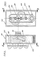
- the two to the top and bottom Injectors 109 leading lines 119 point in the Figures 4 and 5 with a course lying in one plane a 90 'sheet.
- the other two distribution lines 119 to the two injectors in between 109 lead, initially emerge horizontally from the Pouring sleeve 117 and run in a spatial Course to the injection nozzles 109 (cf. in particular FIG. 2).
- a heater e.g. a heating cartridge
- short Heating element 127 used in the cavity 125 of the hollow body 115 or below.
- the Cartridge 127 protected in a tube 129 that on is open to both sides and replacing the Heating cartridge 127 allows to open without opening the hollow body 115 have to.
- a heat-conducting medium e.g. a liquid, such as oil or a gas, completely filled.
- the medium surrounds itself in the cavity 125 located distribution lines 119 and also the Spout sleeve 117.
- baffles 131 used which heated by the heating element 127 Medium within a narrow channel 133 along the stacked distribution lines 119 upwards lead and the thereby cooled above and therefore specifically heavier medium outside the baffles 131 let it sink down where it is on heating element 127 is reheated.
Landscapes
- Engineering & Computer Science (AREA)
- Manufacturing & Machinery (AREA)
- Mechanical Engineering (AREA)
- Moulds For Moulding Plastics Or The Like (AREA)
- Injection Moulding Of Plastics Or The Like (AREA)
Description
Die Verteilrohre lassen sich - da frei durch den Hohlraum verlaufend eingelegt - mit optimalen Biegeradien herstellen, und deren Länge kann, falls erwünscht, für alle Rohre unabhängig vom Abstand der Eintrittsstelle des Kunststoffs in den Kanalblock identisch ausgeführt sein.
Dies ergibt eine gleich lange Verweilzeit des Kunststoffes innerhalb der Verteilrohre und folglich an allen Einspritzdüsen gleiche Bedingungen.
- Figur 1
- einen Querschnitt durch ein Heisskanal-Spritzwerkzeug mit vier vertikal übereinanderliegenden Einspritzdüsen,
- Figur 2
- einen Querschnitt längs Linie II-II durch den Verteilblock in Figur 1,
- Figur 3
- einen Querschnitt durch eine weitere Ausgestaltung der Erfindung längs Linie III-III in Figur 4 mit vier übereinanderliegenden Einspritzdüsen,
- Figur 4
- einen Querschnitt längs Linie IV-IV in Figur 3.
Claims (5)
- Heisskanal-Spritzwerkzeug (101), umfassend eine Hotrunnerplatte (105) mit einem Hohlraum (125) mit einem wärmeleitenden flüssigen oder gasförmigem Medium und mit einer Heizung, in welcher Hotrunnerplatte (105) mindestens eine Verteilleitung (119) das flüssige Kunststoffmaterial von der Ausgussbüchse (117) zu der mindestens einen Einspritzdüse (109) führt, wobei im Hohlraum (125) des Hohlkörpers (115) die mindestens eine Verteilleitung (119) von einer zentralen Verteilleitung, die in den Hohlraum (125) mündet, zu der mindestens einen beabstandet angeordneten Einspritzdüse (109) geführt wird, dadurch gekennzeichnet, dass die Heizung als Heizelement (127) ausgebildet und unterhalb der mindestens einen Verteilleitung (119) angeordnet ist, und dass das Heizelement (127) in einem Rohr (129) innerhalb oder ausserhalb an der Unterseite des Hohlraums (115) eingesetzt und von aussen auswechselbar ist.
- Heisskanal-Spritzwerkzeug nach Anspruch 1, dadurch gekennzeichnet, dass mehrere Verteilleitungen (119) gleicher Länge innerhalb des Hohlraumes (125) angeordnet sind und aus knickfrei gebogenen Rohren bestehen.
- Heisskanal-Spritzwerkzeug nach einem der Ansprüche 1 oder 2, dadurch gekennzeichnet, dass das Heizelement (127) im Bereich des Bodens des Hohlraumes (125) eingesetzt ist.
- Heisskanal-Spritzwerkzeug nach einem der Ansprüche 1 bis 3, dadurch gekennzeichnet, dass im Hohlraum (125) seitlich der Verteilleitungen (119) Leitbleche (131) angeordnet sind.
- Heieskanal-Spritzwerkzeug nach einem der Ansprüche 3 und 4, dadurch gekennzeichnet, dass die wärmeleitende Flüssigkeit durch Konvektion oder durch eine Pumpe innerhalb des Hohlraums (125) umgewälzt wird.
Applications Claiming Priority (3)
| Application Number | Priority Date | Filing Date | Title |
|---|---|---|---|
| CH250496 | 1996-10-14 | ||
| CH250496 | 1996-10-14 | ||
| EP97900928A EP0820374B1 (de) | 1996-02-07 | 1997-02-05 | Heisskanal-spritzwerkzeug |
Related Parent Applications (1)
| Application Number | Title | Priority Date | Filing Date |
|---|---|---|---|
| EP97900928A Division EP0820374B1 (de) | 1996-02-07 | 1997-02-05 | Heisskanal-spritzwerkzeug |
Publications (3)
| Publication Number | Publication Date |
|---|---|
| EP0960714A2 EP0960714A2 (de) | 1999-12-01 |
| EP0960714A3 EP0960714A3 (de) | 2000-03-22 |
| EP0960714B1 true EP0960714B1 (de) | 2002-11-20 |
Family
ID=4235292
Family Applications (1)
| Application Number | Title | Priority Date | Filing Date |
|---|---|---|---|
| EP99202899A Expired - Lifetime EP0960714B1 (de) | 1996-10-14 | 1997-02-05 | Heisskanal-Spritzwerkzeug |
Country Status (4)
| Country | Link |
|---|---|
| EP (1) | EP0960714B1 (de) |
| AT (1) | ATE228052T1 (de) |
| DE (1) | DE59708786D1 (de) |
| PL (1) | PL182859B1 (de) |
Families Citing this family (5)
| Publication number | Priority date | Publication date | Assignee | Title |
|---|---|---|---|---|
| CN101244621B (zh) * | 2008-03-13 | 2013-01-23 | 衡阳华意机械有限公司 | 一种橡胶注射成型的冷流道 |
| US8206146B2 (en) * | 2009-12-08 | 2012-06-26 | Husky Injection Molding Systems Ltd. | Mold-tool system having a manifold body defining uninterrupted melt channels |
| WO2011081694A1 (en) | 2009-12-31 | 2011-07-07 | Husky Injection Molding Systems Ltd. | Mold-runner system having independently controllable shooting-pot assemblies |
| DE102010020077A1 (de) * | 2010-05-10 | 2011-12-15 | Günther Heißkanaltechnik GmbH | Heißkanaldüse und Spritzgießwerkzeug mit einer Heißkanaldüse |
| CN104842517A (zh) * | 2015-04-22 | 2015-08-19 | 苏州好特斯模具有限公司 | 一种平衡型超薄导光板用热流道系统 |
Family Cites Families (7)
| Publication number | Priority date | Publication date | Assignee | Title |
|---|---|---|---|---|
| GB243514A (en) * | 1924-11-17 | 1925-12-03 | Praecisionsgussfabrik Gebr Eck | Apparatus for melting non-metallic especially incombustible celluloid masses to be used in apparatus for casting under pressure |
| US2354363A (en) * | 1943-04-23 | 1944-07-25 | Arthur A Burry | Means for heating thermoplastic materials for molding |
| FR1188316A (fr) * | 1957-12-13 | 1959-09-22 | Fr Des Procedes Dykehouse Soc | Perfectionnements aux têtes chauffantes des machines à mouler par injection |
| US3790324A (en) * | 1972-06-14 | 1974-02-05 | Young Rubber Co | Extension runner system sprue arrangements for molding apparatus |
| GB1535164A (en) * | 1975-12-02 | 1978-12-06 | Rohm & Haas Ltd | Hot runner |
| JPS60165462A (ja) * | 1984-02-09 | 1985-08-28 | Hitachi Cable Ltd | 加熱装置 |
| JPH06262650A (ja) * | 1993-02-04 | 1994-09-20 | Sadao Shimizu | 滑らかな曲線の樹脂通路を内蔵する射出成形機用マニーホールドの製造法 |
-
1997
- 1997-02-05 AT AT99202899T patent/ATE228052T1/de not_active IP Right Cessation
- 1997-02-05 PL PL97345366A patent/PL182859B1/pl not_active IP Right Cessation
- 1997-02-05 EP EP99202899A patent/EP0960714B1/de not_active Expired - Lifetime
- 1997-02-05 DE DE59708786T patent/DE59708786D1/de not_active Expired - Lifetime
Also Published As
| Publication number | Publication date |
|---|---|
| PL182859B1 (pl) | 2002-03-29 |
| DE59708786D1 (de) | 2003-01-02 |
| ATE228052T1 (de) | 2002-12-15 |
| EP0960714A2 (de) | 1999-12-01 |
| EP0960714A3 (de) | 2000-03-22 |
Similar Documents
| Publication | Publication Date | Title |
|---|---|---|
| DE60220814T2 (de) | Schmelzklebstoff-auftragsvorrichtung mit einem zentral angeordneten verteiler und möglichkeit zur lokalen beheizung | |
| DE3624844A1 (de) | Temperiergeraet fuer fluessige klebstoffe | |
| DE3424569A1 (de) | Beheizter verteilerkopf an spritzgussformen fuer kunststoffe | |
| DE1908207A1 (de) | Beheizbarer Spinnbalken zum Erzeugen von Endlosfaeden aus synthetischem Polymeren | |
| EP0810414B1 (de) | Wärmetauscher zum Kühlen von Spaltgas | |
| DE3113495C2 (de) | Spinnbalken für Schmelzspinnanlagen für synthetische Hochpolymere | |
| WO1997028945A1 (de) | Heisskanal-spritzwerkzeug | |
| DE10359795A1 (de) | Strangverdampfervorrichtung | |
| EP0960714B1 (de) | Heisskanal-Spritzwerkzeug | |
| DE19780093B4 (de) | Verfahren und Vorrichtung zum Kühlen und gegebenenfalls Kalibrieren von Gegenständen aus Kunststoff | |
| DE19700028A1 (de) | Vorrichtung und Verfahren zur Kühlung und Evakuierung von Formkörpern in Wellrohrformmaschinen | |
| DE10353696A1 (de) | Düse mit Wärmeleitvorrichtung | |
| DE3331113A1 (de) | Temperierbare form fuer formteile aus kunststoffen | |
| DE2344791A1 (de) | Vorrichtung zum schmelzen und verteilen von thermoplastischen materialien | |
| EP0722075A1 (de) | Hochleistungskapillar-Wärmeaustauscher | |
| DE1801396B2 (de) | Fliessbett beschichtungsvorrichtung | |
| EP0079330B1 (de) | Kokille zum mehrfachstranggiessen von drähten und strängen mit kleinen querschnitten aus metall | |
| DE4200982A1 (de) | Spritzgussvorrichtung mit eingebauter kuehlung in einem vorderbereich der duese | |
| DE3613535A1 (de) | Behandlungsvorrichtung zur warm- oder kaltbehandlung von fluiden | |
| EP0215327B1 (de) | Anströmboden mit Düsen für einen Fliessbett-Apparat | |
| EP0672870B1 (de) | Vorrichtung zum Erwärmen von Wasser, insb. Warmwasserheizkessel | |
| DE4212335C2 (de) | Extrusionsvorrichtung zur Herstellung von Platten | |
| DE19500421A1 (de) | Hochleistungskapillar-Wärmeaustauscher | |
| DE19622139A1 (de) | Wärmetauscher zum Kühlen von Spaltgas | |
| DE3610148C2 (de) |
Legal Events
| Date | Code | Title | Description |
|---|---|---|---|
| PUAI | Public reference made under article 153(3) epc to a published international application that has entered the european phase |
Free format text: ORIGINAL CODE: 0009012 |
|
| 17P | Request for examination filed |
Effective date: 19990906 |
|
| AC | Divisional application: reference to earlier application |
Ref document number: 820374 Country of ref document: EP |
|
| AK | Designated contracting states |
Kind code of ref document: A2 Designated state(s): AT BE CH DE DK ES FI FR GB IE IT LI NL PT SE |
|
| PUAL | Search report despatched |
Free format text: ORIGINAL CODE: 0009013 |
|
| AK | Designated contracting states |
Kind code of ref document: A3 Designated state(s): AT BE CH DE DK ES FI FR GB IE IT LI NL PT SE |
|
| AKX | Designation fees paid |
Free format text: AT BE CH DE DK ES FI FR GB IE IT LI NL PT SE |
|
| 17Q | First examination report despatched |
Effective date: 20010208 |
|
| GRAG | Despatch of communication of intention to grant |
Free format text: ORIGINAL CODE: EPIDOS AGRA |
|
| GRAG | Despatch of communication of intention to grant |
Free format text: ORIGINAL CODE: EPIDOS AGRA |
|
| GRAH | Despatch of communication of intention to grant a patent |
Free format text: ORIGINAL CODE: EPIDOS IGRA |
|
| GRAH | Despatch of communication of intention to grant a patent |
Free format text: ORIGINAL CODE: EPIDOS IGRA |
|
| GRAA | (expected) grant |
Free format text: ORIGINAL CODE: 0009210 |
|
| AC | Divisional application: reference to earlier application |
Ref document number: 820374 Country of ref document: EP |
|
| AK | Designated contracting states |
Kind code of ref document: B1 Designated state(s): AT BE CH DE DK ES FI FR GB IE IT LI NL PT SE |
|
| PG25 | Lapsed in a contracting state [announced via postgrant information from national office to epo] |
Ref country code: NL Free format text: LAPSE BECAUSE OF FAILURE TO SUBMIT A TRANSLATION OF THE DESCRIPTION OR TO PAY THE FEE WITHIN THE PRESCRIBED TIME-LIMIT Effective date: 20021120 Ref country code: IE Free format text: LAPSE BECAUSE OF FAILURE TO SUBMIT A TRANSLATION OF THE DESCRIPTION OR TO PAY THE FEE WITHIN THE PRESCRIBED TIME-LIMIT Effective date: 20021120 Ref country code: GB Free format text: LAPSE BECAUSE OF FAILURE TO SUBMIT A TRANSLATION OF THE DESCRIPTION OR TO PAY THE FEE WITHIN THE PRESCRIBED TIME-LIMIT Effective date: 20021120 Ref country code: FI Free format text: LAPSE BECAUSE OF FAILURE TO SUBMIT A TRANSLATION OF THE DESCRIPTION OR TO PAY THE FEE WITHIN THE PRESCRIBED TIME-LIMIT Effective date: 20021120 |
|
| REF | Corresponds to: |
Ref document number: 228052 Country of ref document: AT Date of ref document: 20021215 Kind code of ref document: T |
|
| REG | Reference to a national code |
Ref country code: GB Ref legal event code: FG4D Free format text: NOT ENGLISH |
|
| REG | Reference to a national code |
Ref country code: CH Ref legal event code: NV Representative=s name: HANS RUDOLF GACHNANG PATENTANWALT Ref country code: CH Ref legal event code: EP |
|
| REG | Reference to a national code |
Ref country code: IE Ref legal event code: FG4D Free format text: GERMAN |
|
| REF | Corresponds to: |
Ref document number: 59708786 Country of ref document: DE Date of ref document: 20030102 |
|
| PG25 | Lapsed in a contracting state [announced via postgrant information from national office to epo] |
Ref country code: AT Free format text: LAPSE BECAUSE OF NON-PAYMENT OF DUE FEES Effective date: 20030205 |
|
| PG25 | Lapsed in a contracting state [announced via postgrant information from national office to epo] |
Ref country code: SE Free format text: LAPSE BECAUSE OF FAILURE TO SUBMIT A TRANSLATION OF THE DESCRIPTION OR TO PAY THE FEE WITHIN THE PRESCRIBED TIME-LIMIT Effective date: 20030220 Ref country code: PT Free format text: LAPSE BECAUSE OF FAILURE TO SUBMIT A TRANSLATION OF THE DESCRIPTION OR TO PAY THE FEE WITHIN THE PRESCRIBED TIME-LIMIT Effective date: 20030220 Ref country code: DK Free format text: LAPSE BECAUSE OF FAILURE TO SUBMIT A TRANSLATION OF THE DESCRIPTION OR TO PAY THE FEE WITHIN THE PRESCRIBED TIME-LIMIT Effective date: 20030220 |
|
| PG25 | Lapsed in a contracting state [announced via postgrant information from national office to epo] |
Ref country code: BE Free format text: LAPSE BECAUSE OF NON-PAYMENT OF DUE FEES Effective date: 20030228 |
|
| NLV1 | Nl: lapsed or annulled due to failure to fulfill the requirements of art. 29p and 29m of the patents act | ||
| GBV | Gb: ep patent (uk) treated as always having been void in accordance with gb section 77(7)/1977 [no translation filed] |
Effective date: 20021120 |
|
| PG25 | Lapsed in a contracting state [announced via postgrant information from national office to epo] |
Ref country code: ES Free format text: LAPSE BECAUSE OF FAILURE TO SUBMIT A TRANSLATION OF THE DESCRIPTION OR TO PAY THE FEE WITHIN THE PRESCRIBED TIME-LIMIT Effective date: 20030529 |
|
| ET | Fr: translation filed | ||
| REG | Reference to a national code |
Ref country code: IE Ref legal event code: FD4D Ref document number: 0960714E Country of ref document: IE |
|
| PLBE | No opposition filed within time limit |
Free format text: ORIGINAL CODE: 0009261 |
|
| STAA | Information on the status of an ep patent application or granted ep patent |
Free format text: STATUS: NO OPPOSITION FILED WITHIN TIME LIMIT |
|
| 26N | No opposition filed |
Effective date: 20030821 |
|
| PGFP | Annual fee paid to national office [announced via postgrant information from national office to epo] |
Ref country code: IT Payment date: 20090129 Year of fee payment: 13 |
|
| PGFP | Annual fee paid to national office [announced via postgrant information from national office to epo] |
Ref country code: FR Payment date: 20090126 Year of fee payment: 13 |
|
| REG | Reference to a national code |
Ref country code: FR Ref legal event code: ST Effective date: 20101029 |
|
| PG25 | Lapsed in a contracting state [announced via postgrant information from national office to epo] |
Ref country code: FR Free format text: LAPSE BECAUSE OF NON-PAYMENT OF DUE FEES Effective date: 20100301 |
|
| PG25 | Lapsed in a contracting state [announced via postgrant information from national office to epo] |
Ref country code: IT Free format text: LAPSE BECAUSE OF NON-PAYMENT OF DUE FEES Effective date: 20100205 |
|
| REG | Reference to a national code |
Ref country code: CH Ref legal event code: NV Representative=s name: GACHNANG AG PATENTANWAELTE, CH |
|
| REG | Reference to a national code |
Ref country code: DE Ref legal event code: R082 Ref document number: 59708786 Country of ref document: DE Representative=s name: CORINNA VOSSIUS IP GROUP PATENT- UND RECHTSANW, DE |
|
| REG | Reference to a national code |
Ref country code: CH Ref legal event code: PCOW Free format text: NEW ADDRESS: INDUSTRIE GROSSHOLZ, 8253 DIESSENHOFEN (CH) Ref country code: CH Ref legal event code: NV Representative=s name: BOVARD AG, CH |
|
| PGFP | Annual fee paid to national office [announced via postgrant information from national office to epo] |
Ref country code: DE Payment date: 20160115 Year of fee payment: 20 Ref country code: CH Payment date: 20160114 Year of fee payment: 20 |
|
| REG | Reference to a national code |
Ref country code: DE Ref legal event code: R071 Ref document number: 59708786 Country of ref document: DE |
|
| REG | Reference to a national code |
Ref country code: CH Ref legal event code: PL |